
日本語
本書では、2015年5月現在のDSB-N1対応機種、レリーズ台/ケー
ブルレリーズの機種ごとの取り付け方について説明しています。
付属の「使用説明書」もあわせてご確認くださいますよう、お願い
申し上げます。
対応機種について
使用可能カメラ:
レンズ交換式アドバンストカメラNikon 1
V3・V2・V1・J4・J3・J2・J1・S2・S1
使用可能 1 NIKKORレンズ:
1 NIKKOR VR 10-30mm f/3.5-5.6
1 NIKKOR 11-27.5mm f/3.5-5.6
1 NIKKOR 18.5mm f/1.8
1 NIKKOR VR 10-30mm f/3.5-5.6 PD-ZOOM
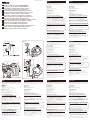
レリーズ台の取り付けについて
(カメラにより取り付け溝が異なります)
取り付けの詳細につきましては、「使用説明書」の「レリーズ台の
取り付け」(13ページ)をご覧ください。(部品名称②、③および
図9は、「使用説明書」内での表記に合わせています。)
②レリーズ台Aには2つの溝があります。カメラにより③レリーズ
台A取り付つまみを取り付ける溝を変えます。上がV3/V2/J4/
J3/J2/J1/S2/S1用、下がV1用です(図9)。
Nikon 1 V3専用(A)スペーサー部品の取り付けについて
DSB-N1にNikon 1 V3を接続する際には、専用の(A)スペー
サーをご使用ください。
③のネジを最大まで緩め、(A)スペーサーを(B)のように配置し
ます。
(C)のようにスペーサー凹み部の面と②の端の面を合わせ、③
のネジを締めます。
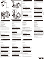
ケーブルレリーズの取り付けについて
(カメラにより取り付け方が異なります)
取り付けの詳細につきましては、「使用説明書」の「ケーブルレリー
ズの取り付け」(14ページ)をご覧ください。(部品名称②および
図12は、「使用説明書」内での表記に合わせています。)
②レリーズ台Aにはネジ穴があります。カメラにより、ケーブルレ
リーズを取り付けるネジ穴を変えます(図12)。
左がV3/J4/J3/J2/J1/S2/S1用、中央がV1、右がV2用です。
Nederlands
Svenska
ItalianoEspañol
English
Français
Printed in Japan(826C)1DE/1503
Deutsch
Jp
Nikon 1 V3/V2/J4/J3/S2/S1をお使いのお客様へ
En
To customers who use the Nikon 1 V3/V2/J4/J3/S2/S1
Es
Para clientes que utilizan la Nikon 1 V3/V2/J4/J3/S2/S1
Fr
Pour les utilisateurs du Nikon 1 V3/V2/J4/J3/S2/S1
De
An Kunden, die die Nikon 1 V3/V2/J4/J3/S2/S1 verwenden
It
Ai clienti che utilizzano il modello Nikon 1 V3/V2/J4/J3/S2/S1
Se
Till kunder som använder Nikon 1 V3/V2/J4/J3/S2/S1
Nl
Voor klanten die de Nikon 1 V3/V2/J4/J3/S2/S1 gebruiken
Ru
Для пользователей фотокамер Nikon 1 V3/V2/J4/J3/S2/S1
Pt
Para clientes que usam a Nikon 1 V3/V2/J4/J3/S2/S1
Pl
Informacja dla użytkowników aparatów Nikon 1 V3/V2/J4/J3/S2/S1
Fi
Nikon 1 V3/V2/J4/J3/S2/S1 -malleja käyttäville asiakkaille
No
Til kunder som bruker Nikon 1 V3/V2/J4/J3/S2/S1
Dk
Til kunder, der bruger Nikon 1 V3/V2/J4/J3/S2/S1
Cz
Pro zákazníky používající fotoaparáty Nikon 1 V3/V2/J4/J3/S2/S1
Ro
Pentru clienţii care utilizează Nikon 1 V3/V2/J4/J3/S2/S1
Hu
A Nikon 1 V3/V2/J4/J3/S2/S1 használói számára
This manual explains how to attach the shutter release base/cable release to all DSB-N1
applicable models as of May 2015.
Please confirm the details of the explanation along with the supplied “Instruction manual”.
Applicable models
Applicable cameras:
Advanced Camera with Interchangeable Lenses
Nikon 1 V3 • V2 • V1 • J4 • J3 • J2 • J1 • S2 • S1
Applicable 1 NIKKOR Lenses:
1 NIKKOR VR 10-30 mm f/3.5-5.6
1 NIKKOR 11-27.5 mm f/3.5-5.6
1 NIKKOR 18.5 mm f/1.8
1 NIKKOR VR 10-30mm f/3.5-5.6 PD-ZOOM
For the attachment of the shutter release base
(the attachment groove varies depending on the camera)
For details on attachment, refer to “Attaching the shutter release base” (Page.29) in the
“Instruction manual”. (The part names labeled 2 and 3, and Fig. 9 pertain to a
description in the “Instruction manual”.)
There are two grooves on 2 shutter release base A. Select the correct groove where 3
attaching knob for shutter release base A is attached, according to the camera in use.
The groove on the upper side is for V3/V2/J4/J3/J2/J1/S2/S1 and the one on the lower side
is for V1. (Fig. 9)
Attaching the special (A) spacer for the Nikon 1 V3
When connecting the Nikon 1 V3 to the DSB-N1, use the special (A) spacer.
Fully loosen the screw at 3, and then place the (A) spacer as shown in (B).
Align the edge of 2 with the protrusion of spacer as shown in (C), and then tighten
the screw at 3.
For the attachment of the cable release,
(the attachment method varies depending on the camera)
For details on attachment, refer to “Attaching the cable release” (Page.30) in the “Instruction
manual”. (The part name labeled 2, and Fig. 12 pertain to a description in the “Instruction
manual”.)
There are two screw holes on 2 shutter release base A. Select the correct screw hole
where the cable release is attached, according to the camera in use. (Fig. 12)
The screw hole on the left-hand side is for V3/J4/J3/J2/J1/S2/S1, the one in the middle is for
V1, and the one on the right-hand side is for V2.
Este manual explica cómo acoplar la base del disparador/disparador por cable en todos los
modelos DSB-N1 aplicables a partir de mayo de 2015.
Confirme los detalles de la explicación que se incluyen junto con el «Manual de
instrucciones» suministrado.
Modelos aplicables
Cámaras aplicables:
Cámara avanzada con objetivos intercambiables
Nikon 1 V3 • V2 • V1 • J4 • J3 • J2 • J1 • S2 • S1
1 objetivo NIKKOR aplicable:
1 NIKKOR VR 10-30 mm f/3,5-5,6
1 NIKKOR 11-27,5 mm f/3,5-5,6
1 NIKKOR 18,5 mm f/1,8
1 NIKKOR VR 10-30 mm f/3,5-5,6 PD-ZOOM
Para el acoplamiento de la base del disparador
(la ranura de acoplamiento varía en función de la cámara)
Para obtener información sobre el acoplamiento, consulte «Acoplamiento de la base del
disparador» (Página 45) en el «Manual de instrucciones». (Los nombres de las piezas etiquetadas
como 2 y 3, y la Fig. 9, pertenecen a una descripción del «Manual de instrucciones»).
Existen dos ranuras en la 2 base del disparador A. Seleccione la ranura adecuada en la
que se va a acoplar la 3 perilla de acoplamiento de la base del disparador A,
conforme a la cámara que se utilice. La ranura de la parte superior es para V3/V2/J4/J3/J2/
J1/S2/S1 y la ranura de la parte inferior es para V1. (Fig. 9)
Acoplamiento del espaciador especial (A) para la Nikon 1 V3
Al conectar la Nikon 1 V3 a DSB-N1, utilice el espaciador especial (A).
Afloje completamente el tornillo en 3 y, a continuación, coloque el espaciador (A)
como se muestra en (B).
Alinee el borde de 2 con el saliente del espaciador como se muestra en (C) y, a
continuación, apriete el tornillo en 3.
Para el acoplamiento del disparador por cable,
(el método de acoplamiento varía en función de la cámara)
Para obtener información sobre el acoplamiento, consulte «Acoplamiento del disparador por
cable» (Página 46) en el «Manual de instrucciones». (El nombre de pieza etiquetada como
2, y la Fig. 12, pertenecen a una descripción del «Manual de instrucciones»).
Existen dos orificios de tornillo en la 2 base del disparador A. Seleccione el orificio de
tornillo adecuado en el que se va a acoplar el disparador por cable, conforme a la cámara que
se utilice. (Fig. 12)
El orificio de tornillo de la izquierda es para V3/J4/J3/J2/J1/S2/S1, el orificio de tornillo del
medio es para V1, y el orificio de tornillo de la derecha es para V2.
In dieser Anleitung wird die Befestigung der Auslöserplatte/des Kabelauslösers an allen
Modellen ab Mai 2015, die DSB-N1 unterstützen, beschrieben.
Bitte prüfen Sie die Einzelheiten der Beschreibung zusammen mit der mitgelieferten
„Bedienungsanleitung“.
Unterstützte Modelle
Unterstützte Kameras:
Kompakte Systemkamera mit Wechselobjektiven
Nikon 1 V3 • V2 • V1 • J4 • J3 • J2 • J1 • S2 • S1
Unterstützte 1 NIKKOR-Objektive:
1 NIKKOR VR 10-30mm 1:3,5-5,6
1 NIKKOR 11-27,5mm 1:3,5-5,6
1 NIKKOR 18,5mm 1:1,8
1 NIKKOR VR 10-30mm 1:3,5-5,6 PD-ZOOM
Zur Befestigung der Auslöserplatte
(die Befestigungsaussparung ist je nach Kamera unterschiedlich)
Ausführliche Informationen zur Befestigung finden Sie unter „Befestigung der Auslöserplatte“ (Seite
77) in der „Bedienungsanleitung“. (Die mit 2 und 3 gekennzeichneten Teilebezeichnungen
sowie Abb. 9 beziehen sich auf eine Beschreibung in der „Bedienungsanleitung“.)
In der 2 Auslöserplatte A gibt es zwei Aussparungen. Wählen Sie je nach verwendeter
Kamera die richtige Aussparung, in der der 3 Befestigungsknopf für die
Auslöserplatte A befestigt wird. Die obere Aussparung ist für die V3/V2/J4/J3/J2/J1/S2/S1
und die untere Aussparung für die V1. (Abb. 9)
Befestigung des speziellen (A) Distanzstücks für die Nikon 1 V3
Verwenden Sie beim Anschließen der Nikon 1 V3 am DSB-N1 das spezielle (A) Distanzstück.
Lösen Sie die Schraube an 3 vollständig und setzen Sie dann das (A) Distanzstück
wie in (B) gezeigt ein.
Richten Sie die Kante von 2 am Vorsprung des Distanzstücks wie in (C) gezeigt aus
und ziehen Sie anschließend die Schraube an 3 fest.
Zur Befestigung des Kabelauslösers
(die Befestigungsmethode ist je nach Kamera unterschiedlich)
Ausführliche Informationen zur Befestigung finden Sie unter „Befestigung des
Kabelauslösers“ (Seite 78) in der „Bedienungsanleitung“. (Die mit 2 gekennzeichnete
Teilebezeichnung sowie Abb. 12 beziehen sich auf eine Beschreibung in der
„Bedienungsanleitung“.)
In der 2 Auslöserplatte A gibt es zwei Schraubenlöcher. Wählen Sie je nach verwendeter
Kamera das richtige Schraubenloch, in dem der Kabelauslöser befestigt wird. (Abb. 12)
Das Schraubenloch links ist für die V3/J4/J3/J2/J1/S2/S1, das mittlere für die V1 und das
rechte für die V2.
Ce mode d’emploi indique comment fixer la base du déclencheur/le câble déclencheur sur
tous les modèles compatibles DSB-N1 à partir de mai 2015.
Veuillez consulter les détails de l’explication qui se trouvent dans le “Mode d’emploi” fourni.
Modèles compatibles
Appareils photo compatibles:
Appareil photo ultraperfectionné avec objectifs interchangeables
Nikon 1 V3 • V2 • V1 • J4 • J3 • J2 • J1 • S2 • S1
Objectifs 1 NIKKOR compatibles:
1 NIKKOR VR f 10-30 mm/3,5-5,6
1 NIKKOR 11-27,5 mm f/3,5-5,6
1 NIKKOR 18,5 mm f/1,8
1 NIKKOR VR 10-30mm f/3,5-5,6 PD-ZOOM
Pour la fixation de la base du déclencheur
(l’encoche de fixation varie en fonction de l’appareil photo)
Pour plus de détails sur la fixation, reportez-vous à “Fixation de la base du déclencheur”
(page61) dans le “Mode d’emploi”. (Les noms des pièces portant le numéro 2 et 3, et la
Fig. 9 se rapportent à une description dans le “Mode d’emploi”.)
La base A du déclencheur 2 comporte deux encoches destinées à recevoir la molette
de fixation pour base A du déclencheur 3. Choisissez l’encoche en fonction de
l’appareil photo utilisé : encoche supérieure pour les modèles V3/V2/J4/J3/J2/J1/S2/S1 et
encoche inférieure pour le modèle V1. (Fig. 9)
Fixation de l'entretoise spéciale (A) pour le Nikon 1 V3
Lorsque vous connectez le Nikon 1 V3 au DSB-N1, utilisez l'entretoise spéciale (A).
Dévissez complètement la vis correspondant à 3, puis placez l'entretoise (A)
comme indiqué sur (B).
Alignez le bord de 2 avec la saillie de l'entretoise comme indiqué sur (C), puis serrez
la vis correspondant à 3.
Pour la fixation du câble déclencheur,
(la méthode de fixation varie en fonction de l’appareil photo)
Pour plus de détails sur la fixation, reportez-vous à “Fixation du câble déclencheur” (page62)
dans le “Mode d’emploi”. (Le nom de la pièce portant le numéro 2 et la Fig.12 se
rapportent à une description dans le “Mode d’emploi”.)
La base A du déclencheur 2 comporte deux trous de vis destinés à recevoir le câble
déclencheur. Choisissez le trou en fonction de l’appareil photo utilisé : (Fig. 12)
Le trou de gauche est pour les modèles V3/J4/J3/J2/J1/S2/S1, celui du milieu pour le
modèle V1 et celui de droite pour le modèle V2.
Nel presente manuale è spiegato come fissare la base scatto otturatore/il cavo flessibile di
scatto a tutti i modelli DSB-N1 applicabili a partire da maggio 2015.
Verificare i dettagli della spiegazione utilizzando il “manuale di istruzioni” fornito.
Modelli applicabili
Fotocamere applicabili:
Fotocamera avanzata con obiettivi intercambiabili
Nikon 1 V3 • V2 • V1 • J4 • J3 • J2 • J1 • S2 • S1
Obiettivi 1 NIKKOR applicabili:
1 NIKKOR VR 10-30 mm f/3.5-5.6
1 NIKKOR 11-27,5 mm f/3.5-5.6
1 NIKKOR 18,5 mm f/1.8
1 NIKKOR VR 10-30mm f/3.5-5.6 PD-ZOOM
Per il montaggio della base scatto otturatore
(la scanalatura di fissaggio varia in funzione della fotocamera)
Per i dettagli relativi al montaggio, consultare la parte intitolata “Montaggio della base scatto
otturatore” (pagina 93) nel “Manuale di istruzioni”. (I nomi dei pezzi numero 2 e 3 e la
Fig. 9 si riferiscono ad una descrizione contenuta nel “Manuale di istruzioni”.)
Due scanalature sono presenti sulla 2 base scatto otturatore A. Selezionare la
scanalatura corretta alla quale è fissata la 3 manopola di fissaggio della base scatto
otturatore A, in funzione della fotocamera utilizzata. La scanalatura superiore è destinata ai
modelli V3/V2/J4/J3/J2/J1/S2/S1; quella inferiore è destinata al modello V1. (Fig. 9)
Montaggio della speciale rondella (A) per il modello Nikon 1 V3
Per il collegamento del modello Nikon 1 V3 al DSB-N1, utilizzare la speciale rondella (A).
Allentare completamente la vite a 3, quindi posizionare la rondella (A) come
illustrato in (B).
Allineare il bordo di 2 con la sporgenza della rondella come illustrato in (C), quindi
serrare la vite a 3.
Per il collegamento del cavo flessibile di scatto
(il metodo di fissaggio varia in funzione della fotocamera)
Per i dettagli relativi al collegamento, consultare la parte intitolata “Collegamento del cavo
flessibile di scatto” (pagina 94) nel “Manuale di istruzioni”. (Il nome del pezzo numero 2 e
la Fig. 12 si riferiscono ad una descrizione contenuta nel “Manuale di istruzioni”.)
Sulla 2 base scatto otturatore A vi sono due fori per viti. Selezionare il foro corretto in
cui sarà collegato il cavo flessibile di scatto, in funzione della fotocamera utilizzata. (Fig. 12)
Il foro per vite a sinistra è previsto per i modelli V3/J4/J3/J2/J1/S2/S1; il foro centrale, per il
modello V1; il foro a destra, per il modello V2.
Deze handleiding legt uit hoe u de sluiterontspannerbasis/kabelontspanner kunt bevestigen
op alle geschikte DSB-N1-modellen, vanaf mei 2015.
Controleer de informatie uit de toelichting in combinatie met de meegeleverde “Handleiding”.
Geschikte modellen
Geschikte camera’s:
Geavanceerde camera met verwisselbare objectieven
Nikon 1 V3 • V2 • V1 • J4 • J3 • J2 • J1 • S2 • S1
Geschikte 1 NIKKOR objectieven:
1 NIKKOR VR 10-30 mm f/3,5-5,6
1 NIKKOR 11-27,5 mm f/3,5-5,6
1 NIKKOR 18,5 mm f/1,8
1 NIKKOR VR 10-30 mm f/3,5-5,6 PD-ZOOM
Voor het bevestigen van de sluiterontspannerbasis
(de bevestigingsgroef verschilt afhankelijk van de camera)
Voor informatie over het bevestigen, raadpleeg “De sluiterontspannerbasis bevestigen”
(pagina 125) in de “Handleiding”. (De onderdeelnamen met nummer 2 en 3 en afb. 9
hebben betrekking op een beschrijving in de “Handleiding”.)
Er bevinden zich twee groeven in 2 sluiterontspannerbasis A. Selecteer de juiste groef
waarbij 3 de bevestigingsknop voor sluiterontspannerbasis A wordt bevestigd op
basis van de camera die wordt gebruikt. De groef aan de bovenkant is voor de V3/V2/J4/J3/
J2/J1/S2/S1 en de groef aan de onderkant is voor de V1. (Afb. 9)
Het speciale (A) afstandsstuk voor de Nikon 1 V3 bevestigen
Gebruik het speciale (A) afstandsstuk wanneer u de Nikon 1 V3 op de DSB-N1 aansluit.
Draai de schroef bij 3 helemaal los en plaats vervolgens het (A) afstandsstuk,
zoals getoond in (B).
Lijn de rand van 2 uit met het uitstekende gedeelte van het afstandsstuk, zoals
getoond in (C), en draai vervolgens de schroef bij 3 vast.
Voor het bevestigen van de kabelontspanner
(de bevestigingsmethode verschilt afhankelijk van de camera)
Voor informatie over het bevestigen, raadpleeg “De kabelontspanner bevestigen” (pagina
126) in de “Handleiding”. (De onderdeelnaam met nummer 2 en afb. 12 hebben
betrekking op een beschrijving in de “Handleiding”.)
Er bevinden zich twee schroefgaten in 2 sluiterontspannerbasis A. Selecteer het juiste
schroefgat voor bevestiging van de kabelontspanner op basis van de gebruikte camera. (Afb.
12)
Het schroefgat aan de linkerkant is bedoeld voor de V3/J4/J3/J2/J1/S2/S1, het schroefgat in
het midden voor de V1, en het schroefgat aan de rechterkant voor de V2.
Bruksanvisningen beskriver hur avtryckarfästet/kabelavtryckaren monteras på alla
tillämpliga modeller av DSB-N1 tillverkade efter maj 2015.
Kontrollera uppgifterna i beskrivningen tillsammans med medföljande ”Bruksanvisning”.
Tillämpliga modeller
Tillämpliga kameror:
Avancerad kamera med utbytbara linser
Nikon 1 V3 • V2 • V1 • J4 • J3 • J2 • J1 • S2 • S1
Tillämpliga 1 NIKKOR-linser:
1 NIKKOR VR 10-30 mm f/3,5-5,6
1 NIKKOR 11-27,5 mm f/3,5-5,6
1 NIKKOR 18,5 mm f/1,8
1 NIKKOR VR 10-30 mm f/3,5-5,6 PD-ZOOM
För montering av avtryckarfäste
(fästets spår varierar beroende på kamera)
För mer information om fästet, se ”Montering av avtryckarfäste” (sid. 109) i ”Bruksanvisning”.
(Delarna som är markerade 2 och 3, samt fig. 9 gäller en beskrivning i
”Bruksanvisning”.)
Det finns två spår på 2 avtryckarfäste A. Välj rätt spår där 3 monteringsratten för
avtryckarfäste A ska sitta beroende på vilken kamera som används. Spåret på den övre
sidan är för V3/V2/J4/J3/J2/J1/S2/S1 och det på den undre sidan är för V1. (Fig. 9)
Montering av distans (A) för Nikon 1 V3
Vid anslutning av Nikon 1 V3 till DSB-N1, måste distans (A) användas.
Lossa skruven helt vid 3 och montera distansen (A) som visas i (B).
Rikta in kanten 2 med den utstickande delen av distansen som visas i (C) och dra
sedan fast skruven vid 3.
För montering av kabelavtryckaren,
(fästmetod varierar beroende på kamera)
För mer information om fästet, se ”Montering av kabelavtryckare” (sid. 110) i
”Bruksanvisning”. (Delen som är markerad 2, samt fig. 12 gäller en beskrivning i
”Bruksanvisning”.)
Det finns två skruvhål på 2 avtryckarfäste A. Välj rätt skruvhål där kabelavtryckaren ska
sitta beroende på vilken kamera som används. (Fig. 12)
Skruvhålet på vänster sida är för V3/J4/J3/J2/J1/S2/S1, det i mitten är för V1 och det till
höger är för V2.
2
3
V3/V2/J4/J3/J2/J1/S2/S1
V1
図
9/Fig.9/Fig. 9/Fig.9/Abb. 9/Fig.9/Fig.9/Afb. 9
3
2
(C)
3
(B)
(A)
Nikon 1 V3
V3/J4/J3/J2/J1/S2/S1
V1
図
12/Fig.12/Fig.12/Fig.12/Abb. 12/Fig.12/Fig.12/Afb. 12
2
V2
La page est en cours de chargement...
-
 1
1
-
 2
2


dans d''autres langues
- italiano: Nikon DSB-N1 Manuale utente
- English: Nikon DSB-N1 User manual
- español: Nikon DSB-N1 Manual de usuario
- Deutsch: Nikon DSB-N1 Benutzerhandbuch
- русский: Nikon DSB-N1 Руководство пользователя
- Nederlands: Nikon DSB-N1 Handleiding
- português: Nikon DSB-N1 Manual do usuário
- dansk: Nikon DSB-N1 Brugermanual
- polski: Nikon DSB-N1 Instrukcja obsługi
- čeština: Nikon DSB-N1 Uživatelský manuál
- svenska: Nikon DSB-N1 Användarmanual
- 日本語: Nikon DSB-N1 ユーザーマニュアル
- suomi: Nikon DSB-N1 Ohjekirja
- română: Nikon DSB-N1 Manual de utilizare
Documents connexes
-
Nikon DSB-N1 Manuel utilisateur
-
-
-
-
-
-
-
Nikon AF-S DX VR Manuel utilisateur
-