
12.0832.0103
ROTRONIC AG, CH-8303 Bassersdorf
Tel. +41 44 838 11 44, www.rotronic.com
ROTRONIC Messgeräte GmbH, D-76275 Ettlingen
Tel. +49 7243 383 250, www.rotronic.de
ROTRONIC SARL, 56, F - 77183 Croissy Beaubourg
Tél. +33 1 60 95 07 10, www.rotronic.fr
ROTRONIC Italia srl, I- 20157 Milano
Tel. +39 2 39 00 71 90, www.rotronic.it
ROTRONIC Instruments (UK) Ltd, West Sussex RH10 9EE
Phone +44 1293 571000, www.rotronic.co.uk
ROTRONIC Instrument Corp, NY 11788, USA
Phone +1 631 427-3898, www.rotronic-usa.com
ROTRONIC Instruments Pte Ltd, Singapore 159836
Phone +65 6376 2107, www.rotronic.sg
ROTRONIC Shanghai Rep. Offi ce, Shanghai 200233, China
Phone +86 40 08162018, www.rotronic.cn
A
A
Herzlichen Glückwunsch zum Kauf Ihres neuen HygroFlex3-Serie Messumformers. Sie haben
damit ein dem neuesten Stand der Technik entsprechendes Gerät erworben. Bitte lesen Sie
diese Anleitung genau durch, bevor Sie das Gerät installieren.
Allgemeine Beschreibung
Die HygroFlex3-Serie Geräte sind universelle Messumformer für die Übertragung von Feuch-
te- und Temperaturmesswerten. Diese Kurzbedienungsanleitung beschränkt sich auf die
Beschreibung der wichtigsten Funktionen und der Installation des Gerätes. Die detaillierte
Bedienungsanleitung fi nden Sie im Internet unter: www.rotronic.com
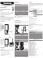
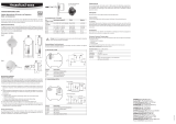
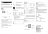
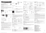
Abmessungen / Anschlüsse
Typ S
Typ R
Mechanische Installation
Achtung:
Um korrekte Messwerte zu erhalten, muss darauf geachtet werden, dass der
Fühler mit der zu messenden Luft umströmt wird.
1. Entfernen Sie, durch lösen der Schraube die Montageplatte.
2. Befestigen Sie die Montageplatte entweder mit 2 oder 4 Schrauben
an der vorgesehenen Stelle.
Service Stecker
(Mini USB)
Sensor
Elektrische Installation
Versorgungsspannung / Technologie
Typ Spannungsversorgung V+ Ausgang
2- oder 2x2 Leiter
HF320- 10...28 VDC: 10 V + (0.02 x Bürde) 4...20 mA
3 / 4 Leiter
HF331 18...40 VDC / 13...28 VAC 0...20 mA
HF332 18...40 VDC / 13...28 VAC 4...20 mA
HF333 6...40 VDC / 5...28 VAC 0...1 V
HF334 10...40 VDC / 8...28 VAC 0...5 V
HF335 18...40 VDC / 13...28 VAC 0...10 V
Achtung:
Falsche Versorgungsspannungen sowie zu grosse Belastungen der Ausgänge
können den Messumformer beschädigen.
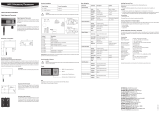
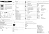
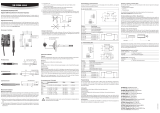
Klemmenbelegung / Anschlussschemata
Anhand der Tabelle «Versorgungsspannung / Technologie» wird der Typ defi niert, um folgende
Anschluss-Schemas verwenden zu können:
2- oder 2x2 Leiter / HF320
Klemme Schema Beschreibung
1 V
+ Spannungsversorgung +
2 T– OUT Temperatur-/Analogausgang +
3 V+ Spannungsversorgung +
4 H– OUT Feuchte- oder Taupunkt-/Analogausgang +
5 & 6 sind nicht angeschlossen
3 / 4 Leiter Schaltung / HF33x
Klemme Schema Beschreibung
1 V+ Spannungsversorgung +/Phase
2 GND GND / Neutral
3 OUT1 Feuchte- oder Taupunkt-/Analogausgang +
4 OUT2 Temperatur-/Analogausgang +
5 & 6 sind nicht angeschlossen
Programmierung
Die Grundeinstellungen der Geräte werden im Werk, gemäss Ihrer Bestellung, vorgenommen.
Die Transmitter werden im Werk justiert, sodass eine Überprüfung oder Nachjustierung
bei der Installation nicht notwendig ist. Die Geräte können sofort nach der Installation in
Betrieb genommen werden.
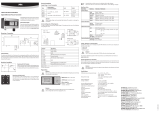
Display
Bei Modellen mit LC-Display, kann der Wert direkt abgelesen werden.
Mess-End-Indikatoren
▲ Steigender Wert (Endwert ist noch nicht erreicht)
▼ Sinkender Wert (Endwert ist noch nicht erreicht)
▲
▼
Konstanter Wert (Endwert ist erreicht)
Skalierung / Justierung / Firmware update
Mit Hilfe der HW4-Software und dem Servicekabel AC3006 können folgende Einstellungen
durchgeführt werden:
• Neuskalierung der Ausgänge
• Justierung
• Firmware update
Eine detaillierte Beschreibung fi nden Sie im Manual welches Sie im Internet unter
www.rotronic-humidity.com herunterladen können.
Technische Daten (Einsatz- & Messbereich)
Feuchte: 0...100 %rF
Temperatur: Typ S: –40...60 °C , ohne Display
Typ R: –10...60 °C, mit Display
Genauigkeit: Typ R: ± 1,0 %rF / Typ S: ± 2 %rF, ± 0.3 K @ 23°C
Schutzart: IP20
Ausgänge: Strom- oder Spannungssignal je nach
Bestellcode UART-Service-Schnittstelle
Stromausgang
Spannungsausgang
Feuchte-, Taupunkt- oder Frostpunkt-
Wert. Je nach bestellter Ausführung.
Temperatur-Wert
Trendindikatoren
Digitaler Messumformer für Feuchte- und Temperatur:
Raumversion
KURZBEDIENUNGSANLEITUNG
V+
GND
GND
OUT1
OUT2
=
~
V+
GND
GND
OUT1
OUT2

12.0832.0103
ROTRONIC AG, CH-8303 Bassersdorf
Tel. +41 44 838 11 44, www.rotronic.com
ROTRONIC Messgeräte GmbH, D-76275 Ettlingen
Tel. +49 7243 383 250, www.rotronic.de
ROTRONIC SARL, 56, F - 77183 Croissy Beaubourg
Tél. +33 1 60 95 07 10, www.rotronic.fr
ROTRONIC Italia srl, I- 20157 Milano
Tel. +39 2 39 00 71 90, www.rotronic.it
ROTRONIC Instruments (UK) Ltd, West Sussex RH10 9EE
Phone +44 1293 571000, www.rotronic.co.uk
ROTRONIC Instrument Corp, NY 11788, USA
Phone +1 631 427-3898, www.rotronic-usa.com
ROTRONIC Instruments Pte Ltd, Singapore 159836
Phone +65 6376 2107, www.rotronic.sg
ROTRONIC Shanghai Rep. Offi ce, Shanghai 200233, China
Phone +86 40 08162018, www.rotronic.cn
A
A
Congratulations on your purchase of the new state-of-the-art HygroFlex3-series transmitter.
Please read these short instructions carefully before installing the device.
General description
The HygroFlex3-series devices are universal transmitters for transmission of humidity and
temperature measurements. These short instructions are limited to a description of the main
functions and installation of the device. The detailed instruction manual can be found on
the internet at: www.rotronic.com
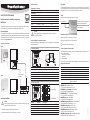
Dimensions / Connections
Type S
Type R
Mechanical installation
Caution:
In order to get correct measurement values, the sensor must be instaled in a way
that the air fl ows around the sensor.
1. Remove the montage plate by drilling out the screws.
2. Mount the mounting plate to the wall by using 2 or 4 screws.
Service connector
(mini USB)
Sensor
Electrical installation
Supply voltage / Technology
Type Supply voltage V+ Output
2- or 2x2-wire
HF320- 10...28 VDC: 10 V + (0.02 x load) 4...20 mA
3 / 4-wire
HF331 18...40 VDC / 13...28 VAC 0...20 mA
HF332 18...40 VDC / 13...28 VAC 4...20 mA
HF333 6...40 VDC / 5...28 VAC 0...1 V
HF334 10...40 VDC / 8...28 VAC 0...5 V
HF335 18...40 VDC / 13...28 VAC 0...10 V
Caution:
Wrong supply voltages and excessively high loading of the outputs can
damage the transmitter.
Terminal confi guration / Connection diagrams
The type is defi ned using the table «Supply voltage / Technology» to then use the following
connection diagrams:
2- or 2x2-wire / HF320
Terminal Schematics Description
1 V
+ Supply voltage +
2 T– OUT Analogue temperature output +
3 V+ Supply voltage +
4 H– OUT Analogue humidity or dew point output +
5 & 6 Not connected
3 / 4-wire circuit / HF33x
Terminal Schematics Description
1 V+ Supply voltage +/Phase
2 GND GND / Neutral
3 OUT1 Analogue humidity or dew point output +
4 OUT2 Analogue temperature output +
5 & 6 Not connected
Programming
The basic settings of the devices are made in the factory according to your order. The transmit-
ters are adjusted in the factory and therefore do not need to be checked and readjusted during
installation. The devices can be started immediately after installation.
Display
In models with LC display the value can be read directly.
Measurement-End-Indicators
▲ Increasing value (End value is not reached yet)
▼ Decreasing value (End value is not reached yet)
▲
▼
Constant value (End value is reached)
Scaling / Adjustment / Firmware update
The following settings can be made with the help of the HW4 software and either the service
cable AC3006 or AC3009:
• new scaling of the outputs
• adjustment
• fi rmware update
You can fi nd a detailed description in the manual that you can download from our web site at:
www.rotronic-humidity.com
Technical data (operation & measurement)
Humidity: 0...100 %rh
Temperature: Type S: –40...60 °C , without display
Type R: –10...60 °C, with display
Accuracy: Type R: ± 1,0 %rh / Type S: ± 2 %rh, ± 0.3 K @ 23°C
Protection: IP20
Outputs: Current or voltage signals depending on order code,
UART service interface
Current output
Voltage output
Humidity-, dew point- or frost point value.
Depends on the ordered version.
Temperature value
Trend indicators
Digital transmitter for humidity & temperature:
Wall Version
SHORT INSTRUCTION MANUAL
V+
GND
GND
OUT1
OUT2
=
~
V+
GND
GND
OUT1
OUT2

12.0832.0103
ROTRONIC AG, CH-8303 Bassersdorf
Tel. +41 44 838 11 44, www.rotronic.com
ROTRONIC Messgeräte GmbH, D-76275 Ettlingen
Tel. +49 7243 383 250, www.rotronic.de
ROTRONIC SARL, 56, F - 77183 Croissy Beaubourg
Tél. +33 1 60 95 07 10, www.rotronic.fr
ROTRONIC Italia srl, I- 20157 Milano
Tel. +39 2 39 00 71 90, www.rotronic.it
ROTRONIC Instruments (UK) Ltd, West Sussex RH10 9EE
Phone +44 1293 571000, www.rotronic.co.uk
ROTRONIC Instrument Corp, NY 11788, USA
Phone +1 631 427-3898, www.rotronic-usa.com
ROTRONIC Instruments Pte Ltd, Singapore 159836
Phone +65 6376 2107, www.rotronic.sg
ROTRONIC Shanghai Rep. Offi ce, Shanghai 200233, China
Phone +86 40 08162018, www.rotronic.cn
Nous vous félicitons d’avoir choisi le nouveau transmetteur de la série HygroFlex3. Vous avez
fait l’acquisition d’un appareil doté de la technologie la plus récente. Nous vous remercions
de lire ce mode d’emploi avant d’installer votre transmetteur.
Généralités
Les appareils de la série HygroFlex3 sont des transmetteurs de mesure universels pour la
transmission de valeurs de mesure d’humidité et de température. Ce mode d’emploi abrégé
se limite à la description des fonctions essentielles de cet appareil et à son installation. Vous
trouverez un mode d’emploi détaillée sur notre site Internet: www.rotronic.com
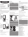
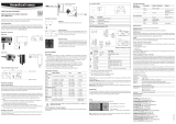
Dimensions / raccordements
Type R
Transmetteurs numériques pour l’humidité
et la température: Version d’intérieur
MODE D'EMPLOI ABRÉGÉ
A
A
Type S
Type R
Installation mécanique
Attention:
Pour obtenir des valeurs de mesure correctes, il est impératif que le capteur
baigne dans l’air de l’environnement à mesurer.
1. Retirer la platine de montage en enlevant les vis.
2. Fixer la platine de montage avec 2 ou 4 vis à l’endroit désiré.
Installation électrique
Tension d’alimentation / technologie
Type Alimentation en tension V+ Sortie
2 conducteurs ou 2x2 conducteurs
HF320- 10...28 VCC: 10 V + (0,02 x charge) 4...20 mA
3 / 4 conducteurs
HF331 18...40 VCC / 13...28 VCA 0...20 mA
HF332 18...40 VCC / 13...28 VCA 4...20 mA
HF333 6...40 VCC / 5...28 VCA 0...1 V
HF334 10...40 VCC / 8...28 VCA 0...5 V
HF335 18...40 VCC / 13...28 VCA 0...10 V
Attention:
Des tensions d’alimentation erronées ainsi que des sollicitations trop fortes des
sorties peuvent endommager le transmetteur de mesure.
Affectation des bornes / schémas de raccordement
Le tableau de tension d’alimentation / technologie sert à défi nir le type d’appareil pour
pouvoir utiliser les schémas de raccordement suivants:
2 conducteurs ou 2x2 conducteurs / HF320
Borne Schéma Description
1 V
+ Alimentation en tension +
2 T– OUT Sortie analogique de température +
3 V+ Alimentation en tension +
4 H– OUT Sortie analogique humidité ou point de rosée +
5 & 6 ne sont pas raccordés
Branchement 3 / 4 conducteurs / HF33x
Borne Schéma Description
1 V+ Alimentation en tension +/Phase
2 GND GND / Neutre
3 OUT1 Sortie analogique humidité ou point de rosée +
4 OUT2 Sortie analogique de température +
5 & 6 ne sont pas raccordés
Connecteur de service
(mini USB)
Elément sensible
Sortie de courant
Sortie de tension
Programmation
Les réglages de base des appareils sont effectués dans l’usine conformément à votre
commande. Les transmetteurs de mesure sont ajustés en usine. De ce fait, une vérifi cation
ou réajustement de l’installation n’est pas nécessaire. Les appareils peuvent être mis en
service immédiatement après l’installation.
Affi chage
Les valeurs sont directement lisibles sur les modèles avec affi chage LC.
Indicateurs de fi n de mesure
▲ Valeur croissante (la valeur défi nitive n’est pas encore atteinte)
▼ Valeur décroissante (la valeur défi nitive n’est pas encore atteinte)
▲
▼
Valeur constante (la valeur défi nitive est atteinte)
Changement d’échelle / ajustage / mise à jour du fi rmware
Le logiciel HW4 et le câble de service AC3006 permettent d’effectuer les réglages suivants:
• Changement d’échelle des sorties
• Ajustage
• Mise à jour du fi rmware
Vous trouverez une description détaillée dans le manuel que vous pouvez télécharger sous
www.rotronic-humidity.com
Caractéristiques techniques (gammes d’utilisation et de mesure)
Humidité: 0...100 %HR
Température: Type S: –40...60 °C , sans affi chage
Type R: –10...60 °C, avec affi chage
Précision: Type R: ± 1,0 %HR / Type S: ± 2 %HR, ± 0,3 K @ 23°C
Type de protection: IP20
Sorties: Signal de courant ou de tension selon le code de commande
Interface de service UART
Valeur d’humidité, point de rosée ou
de gel. Selon la version commandée.
Valeur de température
Indicateur de tendance
V+
GND
GND
OUT1
OUT2
=
~
V+
GND
GND
OUT1
OUT2

12.0832.0103
ROTRONIC AG, CH-8303 Bassersdorf
Tel. +41 44 838 11 44, www.rotronic.com
ROTRONIC Messgeräte GmbH, D-76275 Ettlingen
Tel. +49 7243 383 250, www.rotronic.de
ROTRONIC SARL, 56, F - 77183 Croissy Beaubourg
Tél. +33 1 60 95 07 10, www.rotronic.fr
ROTRONIC Italia srl, I- 20157 Milano
Tel. +39 2 39 00 71 90, www.rotronic.it
ROTRONIC Instruments (UK) Ltd, West Sussex RH10 9EE
Phone +44 1293 571000, www.rotronic.co.uk
ROTRONIC Instrument Corp, NY 11788, USA
Phone +1 631 427-3898, www.rotronic-usa.com
ROTRONIC Instruments Pte Ltd, Singapore 159836
Phone +65 6376 2107, www.rotronic.sg
ROTRONIC Shanghai Rep. Offi ce, Shanghai 200233, China
Phone +86 40 08162018, www.rotronic.cn
A
A
Ci congratuliamo per il Vostro acquisto di un nuovo trasduttore della serie HygroFlex3. Avete
acquistato uno strumento al passo con le tecnologie più moderne. Prima di installare lo
strumento, si prega di leggere la presente guida rapida.
Descrizione generica
Gli apparecchi della serie HygroFlex3 sono trasduttori universali per la trasmissione di valori
di umidità e temperatura. La presente guida rapida si limita a descrivere le funzioni principali
dello strumento e la sua installazione. Le istruzioni d’uso dettagliate sono disponibili in
internet all’indirizzo: www.rotronic.com
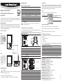
Dimensioni / connessioni
Typo S
Typo R
Installazione meccanica
Attenzione:
per ottenere valore corretti di misurazione, si deve installare la sonda in modo
che il fl usso d’aria la circondi.
1. Asportare la piastra di montaggio allentando le viti.
2. Fissare la piastra di montaggio con 2 o 4 viti al punto previsto di installazione.
Connettore di servizio
(mini USB)
Sensore
Installazione elettrica
Tensione di alimentazione / tecnologia
Tipo Tensione di alimentazione V+ Uscita
2 o 2x2 conduttori
HF320- 10...28 VDC: 10 V + (0,02 x carico) 4...20 mA
3/4 conduttori
HF331 18...40 VDC / 13...28 VAC 0...20 mA
HF332 18...40 VDC / 13...28 VAC 4...20 mA
HF333 6...40 VDC / 5...28 VAC 0...1 V
HF334 10...40 VDC / 8...28 VAC 0...5 V
HF335 18...40 VDC / 13...28 VAC 0...10 V
Attenzione:
Tensioni di alimentazione errate o carichi eccessivi sulle uscite possono
danneggiare il trasduttore.
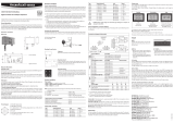
Occupazione dei morsetti / schemi di collegamento
In base alla tabella Tensione di alimentazione / tecnologia si defi nisce il tipo, per poter
quindi utilizzare i seguenti schemi di collegamento:
2 o 2x2 conduttori / HF320
Morsetto Schema Descrizione
1 V+ Tensione di alimentazione +
2 T– OUT Uscita analogica temperatura +
3 V+ Tensione di alimentazione +
4 H– OUT Uscita analogica umidità o punto di rugiada +
5 & 6 non collegati
Circuito a 3/4 conduttori / HF33x
Morsetto Schema Descrizione
1 V+ Tensione di alimentazione +/Fase
2 GND GND / Neutro
3 OUT1 Uscita analogica umidità o punto di rugiada +
4 OUT2 Uscita analogica temperatura +
5 & 6 non collegati
Programmazione
Le impostazioni base dello strumento sono effettuate di fabbrica, in accordo alla Vostra
ordinazione. I trasmettitori sono regolati di fabbrica e pertanto in fase di installazione no è
necessario effettuare un controllo o una successiva regolazione. Pertanto dopo l’installazione
è possibile mettere immediatamente in funzione gli strumenti.
Display
I modelli con display LCD permettono la lettura immediata del valore.
Indicatori di fi ne misurazione
▲ Valore in crescita (il valore di fondo scala non è ancora stato raggiunto)
▼ Valore in diminuzione (il valore di fondo scala non è ancora stato raggiunto)
▲
▼
Valore costante (il valore di fondo scala è stato raggiunto)
Scala / Regolazione / Firmware update
Grazie al software HW4 e al cavo di servizio AC3006 si possono effettuare le seguenti
impostazioni:
• Nuova scala delle uscite
• Regolazione
• Firmware update
Una descrizione dettagliata è riportata nel manuale disponibile per lo scarico all’indirizzo
Internet: www.rotronic-humidity.com
Dati tecnici (range di utilizzo e di misurazione)
Umidità: 0...100 %UR
Temperatura: Tipo S: –40...60 °C, senza display
Tipo R: –10...60 °C, con display
Precisione Tipo R: ±1,0 %UR / tipo S: ± 2 %UR, ± 0,3 K @ 23°C
Standard di protezione: IP20
Uscite: Segnale di corrente o di tensione, uscita digitale in base
al codice d’ordine, interfaccia di servizio UART
Valore di umidità, punto di rugiada o
punto del ghiaccio.
Varia in base al modello ordinato.
Valore della temperatura
Indicatori di trend
Trasduttori digitali per umidità e temperatura:
Versione statica
MANUALE D'ISTRUZIONI BREVE
Uscita di corrente
Uscita di tensione
V+
GND
GND
OUT1
OUT2
=
~
V+
GND
GND
OUT1
OUT2
-
 1
1
-
 2
2
-
 3
3
-
 4
4


Rotronic hf3 Manuel utilisateur
- Taper
- Manuel utilisateur
- Ce manuel convient également à
dans d''autres langues
- italiano: Rotronic hf3 Manuale utente
- English: Rotronic hf3 User manual
- Deutsch: Rotronic hf3 Benutzerhandbuch
Documents connexes
-
 Rotronic hf3 Short Instruction Manual
-
 Rotronic HS5 Short Instruction Manual
-
 Rotronic PF4 Short Instruction Manual
-
 Rotronic CRP5 Manuel utilisateur
-
 Rotronic HF5NEW Manuel utilisateur
-
Rotronic HM4 Short Instruction Manual
-
 Rotronic XB OEM Short Instruction Manual
-
 Rotronic hf5 Manuel utilisateur
-
 Rotronic HF8 Short Instruction Manual
-
 Rotronic HF4 Manuel utilisateur


