Extron AXP 50 C AT Manuel utilisateur
- Catégorie
- Matériel musical
- Taper
- Manuel utilisateur

1
Product Category
IMPORTANT:
Refer to www.extron.com for the
complete user guide and installation
instructions befor
e connecting the
pr
oduct to the power sour
ce.
This guide provides basic instructions for an experienced technician
to install the AXP50CAT Audio Expansion Processor. For additional
information and specications, see the AXP50 CAT product page at
www.extron.com.
AXP50CAT • Setup Guide
Disconnect Power and Mount the AXP50CAT
Disconnect power to the AXP50CAT and turn off all devices that will be connected to it. The AXP50CAT is housed in a half
rack width, 9.5 inch deep, 1U high metal enclosure that can sit on a table with the provided rubber feet, or mount underneath a
conference table, inside a credenza, or anywhere microphones or other sources are located. Select a suitable mounting location,
then choose an appropriate mounting option.
Make all external device connections before applying power.
32:(5
9
$0$;
5(6(7
&21752/
$7
0,&/,1(,16
*,1 22
*,1 22 *,1 22
*,1 22 *,1 22
$;3 &$7
$%
&'
(
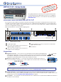
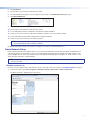
Figure 1. AXP 50 C AT Rear Panel
A
12 VDC power input.
D
Four RJ-45 Ethernet connectors. The ports are used for both
digital audio and control.
E
Reset button.
B
Five 3.5 mm, 4-pole captive screw connectors for
digital I/O trigger and tally back.
C
Five 3.5 mm, 3-pole captive screw connectors for
analog mic or line audio input.
Connections
B
Digital I/O connectors — Five connectors associated with the mic/line inputs provide digital input
and output ports designed to connect to microphones with logic circuits. Each has an input (IN) and
two output (O1 and O2) ports. The input port can enable mic mute from a remote source. The two
output ports can provide tally back to the mic LEDs to indicate mic status.
C
Mic/Line 1-5 input connectors — Connect up to ve balanced or unbalanced microphone or
mono line level devices using the 3-pole, 3.5mm captive screw connectors. Wire as shown below.
Audio Output Wiring
Audio Input Wiring
Unbalanced Output
Tip
Sleeve
NO Ground Here
Balanced Output
Tip
Sleeve
Ring
Balanced Input
Tip
Sleeve
Ring
Tip
Sleeve
Unbalanced Input
ATTENTION: For unbalanced audio outputs,
connect the sleeves to the ground contact.
DO NOT connect the sleeves to the
negative (–) contacts.
NOTE: An input can be analog or digital. Each channel can select either the associated rear panel analog input or
the AT digital channel input assigned by Dante Controller (see Dante Operation on page9).
D
AT port connectors — A 4-port Gigabit switch with RJ-45 connectors for digital audio transport and communications.
Connect one or more ports to a LAN using standard CAT cable. Connect one or more AXP50CATs to a DMP128AT to form
a larger matrix system (see Creating a Physical Dante Network on page8).
E
Reset button — The reset button can return the AXP50CAT to a default state, see (“AXP50CAT Hardware Reset Mode” in
the AXP50CAT User Guide).
Do not tin the wires!
(5 mm) MAX.
3 "
16
I
G
O1
O2
Digital I/O Wiring

2
AXP50CAT • Setup Guide (Continued)
Control Connection
LAN — Using a standard Ethernet cable, connect to a network via one of the four AT ports (see figure 1
D
on page 1).
The control device must be connected to the same network. One of the four Ethernet ports can be dedicated as a control
connection. Communication between the AXP50CAT and a controlling device or software such as DataViewer is via a TCP
socket using port 4333. Dante controller displays the current IP address.
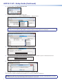
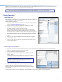
To nd the IP address of a Dante device, the name of the device must be known (see Rename an AXP50CAT: on
page5).
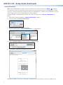
1. Open Dante Controller for Windows (see Dante Network Setup on page5).
2. From the toolbar, select Device>Device View.
3. The Dante Controller - Device View dialog opens.
Select your device from the (Select a Dante Device...) drop-down list.
AXP50-063f70
AXP50-Podium
AXP50-Lecture Hall
AXP50-ConfRm 01
AXP50-ConfRm 02
DMP128-Rack #1
DMP128-Lecture Hall
DMP128-Rack #2
AXP50- 063f70
4. Click the Network Cong tab to open the network conguration page.
AXP50-063f70
5. The IP address, subnet mask, and gateway are shown.
AXP50-063f70
Dante Controller - Device View (AXP50-063f70)
192 168 254 254
255 255 00
0000
Write down the address for use in the control device or DataViewer and use port 4443 to connect to the AXP50CAT.

3
Product Category
ATTENTION:
• Always use a power supply provided by or specied by Extron.
Use of an unauthorized power supply voids all regulatory
compliance certication and may cause damage to the supply
and the end product.
• Utilisez toujours une source d’alimentation fournie par Extron.
L’utilisation d’une source d’alimentation non autorisée annule
toute conformité réglementaire et peut endommager la source
d’alimentation ainsi que l’unité.
• Unless otherwise stated, the AC/DC adapters are not suitable
for use in air handling spaces or in wall cavities. The power
supply is to be located within the same vicinity as the Extron
AV processing equipment in an ordinary location, Pollution
Degree2, secured to the equipment rack within the dedicated
closet, podium, or desk.
• Sauf mention contraire, les adaptateurs AC/DC ne sont pas
appropriés pour une utilisation dans les espaces d’aération ou
dans les cavités murales. La source d’alimentation doit être
située à proximité de l’équipement de traitement audiovisuel
dans un endroit ordinaire, avec un degré2 de pollution, fixé à
un équipement de rack à l’intérieur d’un placard, d’une estrade,
ou d’un bureau.
• The installation must always be in accordance with the
applicable provisions of National Electrical Code ANSI/NFPA
70, article 725 and the Canadian Electrical Code part 1, section
16. The power supply shall not be permanently xed to building
structure or similar structure.
• Cette installation doit toujours être en accord avec les mesures
qui s’applique au National Electrical Code ANSI/NFPA70,
article725, et au Canadian Electrical Code, partie1, section16.
La source d’alimentation ne devra pas être fixée de façon
permanente à une structure de bâtiment ou à une structure
similaire.
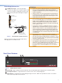
Power Supply Connection
A
12 VDC power input – Connect the provided
12VDC power supply to the rear panel captive screw
connector (see gure2) and plug in the power cord.
Verify the front panel power LED lights (see gure 3,
below).
Rear Panel
Power Receptacle
DC Power Cord
Captive Screw
Connector
Ground
all devices.
External
Power Supply
(12 VDC, 1 A max.,
Extron P/N 28-071-57LF)
– Return
+12 VDC input
Ridged
Smooth
1A MAX
100-240V 50-60Hz
Figure 2. External Power Supply Connection
Front Panel Features
$8',2(;3$16,21352&(6625
&/,3
6,*1$/
,13876
([WURQ
$;3&$7
$%&
Figure 3. AXP50CAT Front Panel
A
Power LED – Lights solid green when the AXP50CAT is powered. Blinks green during bootup or a rmware update.
B
Input Signal indicators — Light when there is an active source on the corresponding input.
C
Clip indicators — Light when the corresponding input signal exceeds -3 dBFS. The clip indicator remains on for 200ms
after the input signal drops below that level.
With all connections made, power up the input devices,
then apply power to the AXP50CAT.

4
AXP50CAT • Setup Guide (Continued)
Dante Controller for Windows and DSP Configurator Software Installation
There are no hardware controls for the AXP50CAT. Dante Controller from Audinate is required to select and route digital inputs
and outputs to connected Dante-compatible devices. DSP Congurator is used for conguration.
Install DSP Congurator and Dante Controller on a PC running Microsoft
®
Windows
®
7
®
or newer. For full details about computer
requirements, see the product page on the Extron website. Dante Controller must be installed to rename the connected
AXP50CAT to assist identication on the network.
Dante Controller for Windows Download
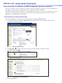
Both software applications are available from the Extron Electronics web page at www.extron.com.
1. From the Extron Electronics web page at www.extron.com, enter AXP50CAT in the search eld and press <Enter>.
The AXP50CAT product page opens.
AXP 50 C AT
11
2
2
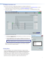
Figure 4. AXP50CAT Product Page
2. Click Downloads (
2
). The Downloads panel opens. Dante Controller and DSP Congurator are listed.
3. Click Dante Controller (
3
).
11
2
2
33
The Download Center page opens.
44
5
5
Figure 5. Download Center - Dante Download
4. Fill in the required elds.

5
Product Category
5. Click Download.
6. Save the le to your desktop (or other known location).
7. If the Download Center page has closed, repeat step 1 and step 2. The Download Center page opens.
8. Click DSP Congurator.
111
2
222
9. Fill in the required elds, then click Download.
10. Save the le to your desktop (or other known location).
11. Locate and double-click the saved Dante controller le to begin installation.
12. Follow the onscreen instructions. When the installation completes, close the installation dialog.
13. Locate and double-click the DSP Congurator le to begin installation.
14. Follow the onscreen instructions to install the program.
NOTE: On the first installation of DSP Configurator, a USB driver automatically loads. Follow the on-screen instructions.
Once the USB driver loads, installation continues.
By default, the program installs in the folder C:\Program Files\Extron\DSP Congurator .
Dante Network Setup
Dante Controller auto-discovers all Dante devices on the network and advertises itself to allow other Dante-enabled devices to
communicate with it. The default device name is the model number followed by the last six digits of the MAC address of the
device. Multiple devices on the same network can present difculty identifying inputs and outputs. To avoid confusion, each
device must be renamed to a unique identier.
NOTE: To simplify renaming, connect only one Dante device to the network at a time. As each device is renamed, it can
remain connected.
Rename an AXP50CAT:
Ensure the control computer and a single AXP50CAT are connected to the same network (see Control Connection on page2).
1. From the start menu select All Programs > Audinate > Dante Controller > Dante Controller.
The Dante Controller - Network View screen opens.
AXP50-Lecture Hall
Dante Receivers
Dante Transmitters
AXP50-Podium
AXP50-ConfRm 01
AXP50-ConfRm 02
DMP128-Rack #1
DMP128-Lecture Hall
DMP128-Rack #2
AXP50-Lecture Hall
AXP50-Podium
AXP50-ConfRm 01
AXP50-ConfRm 02
DMP128-Rack #1
DMP128-Lecture Hall
DMP128-Rack #2
AXP50-063f70
AXP50-063f70
All Dante devices on the network are discovered and listed.

6
AXP50CAT • Setup Guide (Continued)
2. From the toolbar, select Device>Device View.
3. The Dante Controller - Device View dialog opens.
Select your device from the (Select a Dante Device...) drop-down list.
AXP50-063f70
AXP50-Podium
AXP50-Lecture Hall
AXP50-ConfRm 01
AXP50-ConfRm 02
DMP128-Rack #1
DMP128-Lecture Hall
DMP128-Rack #2
AXP50- 063f70
NOTE: If there are multiple AXP50s connected to the network that have not been renamed, to identify an individual
device you must obtain the MAC address of the desired device from the label on the rear panel.
The Device View dialog populates with the selected AXP50CAT information.
AXP50-063f70
Dante Controller - Device View (AXP50-063f70)
AXP50- 063f70
AXP50-Podium
AXP50-Lecture Hall
AXP50-ConfRm 01
AXP50-ConfRm 02
DMP128-Rack #1
DMP128-Lecture Hall
DMP128-Rack #2
4. Click the Device Cong tab to open the device conguration page.
AXP50-063f70
5. In the Rename Device panel, type the new name of the device in the text eld. No spaces are allowed in the name.
AXP50-Lab
AXP50-Lab
6. Click <Enter>. A warning opens.
AXP50-Lab
Renaming a device breaks existing audio routes from this device to other devices.
Are you sure you want to rename AXP50-063f70 to AXP50-Lab?
7. Click Yes to enter the new name, then close the Device Conguration dialog.
The new name is written to the AXP50CAT. Repeat as necessary for all AXP50CAT devices.
NOTE: After the AXP50CAT is renamed, it can remain connected to the network. However, subsequent devices must be
connected one at a time and renamed before the next device is connected.

7
Product Category
X
AXP50-Lab
AXP50-Lecture Hall
AXP50-ConfRm 01l
AXP50-ConfRm 02
AXP50-Podium
DMP128-Rack #1
DMP128-Lecture Hall
DMP128-Rack #2
Connect to device...
Please select the appropriate communication
Dante
Port Configuration
Dante Devices:
To Configure the AXP50CAT:
After the name of the device is changed, DSP Congurator can congure the AXP50CAT.
1. Ensure the control computer and AXP50CAT are connected to the same network (see Control Connection on page2)
and the AXP50CAT is renamed for identication (see Rename an AXP50CAT: on page5).
2. Start the DSPCongurator software. From the drop-down list on the splash page, select AXP50CAT and press OK.
The main screen opens.
3. The program starts in Emulate mode.
a. To create a conguration ofine and upload (push) it to the AXP50CAT at a later
time, remain in Emulate mode.
b. To push a conguration to the device, pull a conguration from the device, or to
make immediate changes to the conguration or operation, select Live mode.
NOTE: Changing from Emulate to Live mode opens the Connect to
device... dialog. Select the connection and follow the on-screen prompts.
The main screen provides access to all the features of the AXP50CAT. Full details
about using the software are found in the AXP50CAT User Guide on the Extron
website or in the DSP Congurator help les.
Building Blocks
The discrete signal paths can be individually loaded with pre-congured, modular
templates called building blocks. These blocks are designed for specic microphones,
source devices, analog and digital inputs, and can streamline initial conguration. The
building blocks contain conguration parameters tailored to a selected input device.
Loading a building block congures each block in the signal path with pre-determined
parameters to match the selected device characteristics. Although tailored for the
specic device, the processing blocks can still be customized, if necessary.

8
AXP50CAT • Setup Guide (Continued)
Creating a Physical Dante Network
A physical network is required to share Dante audio channels between AXP50CAT devices and a DMP128 AT. Both the
AXP50CAT and DMP128AT contain a 4-port Gigabit switch with four RJ-45 connectors located on the back panel that accepts
standard network cables.
A DMP128-based Dante network can be congured in a daisy-chain or star network topology using the four port switch and the
Dante Controller in switched mode.
Star network topology places one DMP128AT as the central unit, which connects directly to up to three more units. Alternatively,
a larger network switch in place of the central DMP128AT, allows more than four AXP50CATs to connect in the star
conguration (see gure 7).
Star Network Topology
100-240V ~ --A MAX
50/60 Hz
LAN
EXP
RS-232
Tx Rx G
RESET
MIC +48V
5678
1234
8
4 1
1 2345G6
1234
78910 G
11 12 13 14 15 G1617181920G
234
56 78
910
11 127
3
6
2
5
1
MIC/LINE INPUT
S
OUTPUTS
DIGITAL I/O
REMOTE AT
DMP 128 C AT
AXP 50 C AT
RESET
1
2345
1
IN G
POWER
12V
1.0A MAX
0102 IN G0102ING01 02 IN G0102ING01 02
2345
234
I/OINPUTS
AT
1
AXP 50 C AT
RESET
1
2345
1
IN G
POWER
12V
1.0A MAX
0102 IN G0102ING01 02 IN G0102ING01 02
2345
234
I/OINPUTS
AT
1
AXP 50 C AT
RESET
1
2345
1
IN G
POWER
12V
1.0A MAX
0102 IN G0102ING01 02 IN G0102ING01 02
2345
234
I/OINPUTS
AT
1
DMP 128 C AT
AXP 50 C AT
AXP 50 C AT
AXP 50 C AT
Figure 7. Star Network Topology
A daisy chain conguration can also be used. Each unit is connected to both the previous unit and the next unit in the chain.
DMP 128 AT
100-240V ~ --A MAX
50/60 Hz
LAN
EXP
RS-232
Tx Rx G
RESET
MIC +48V
5678
1234
8
4 1
1 2345G6
1234
78910G
11 12 13 14 15 G1617181920G
234
56 78
910
11 127
3
6
2
5
1
MIC/LINE INPUT
S
OUTPUTS
DIGITAL I/O
REMOTE AT
DMP 128 C AT
AXP 50 C AT
RESET
1
2345
1
IN G
POWER
12V
1.0A MAX
0102 IN G0102ING01 02 IN G0102ING01 02
2345
234
I/OINPUTS
AT
1
AXP 50 C AT
RESET
1
2345
1
IN G
POWER
12V
1.0A MAX
0102 IN G0102ING01 02 IN G0102ING01 02
2345
234
I/OINPUTS
AT
1
AXP 50 C AT
RESET
1
2345
1
IN G
POWER
12V
1.0A MAX
0102 IN G0102ING01 02 IN G0102ING01 02
2345
234
I/OINPUTS
AT
1
AXP 50 C AT #1 AXP 50 C AT #2 AXP 50 C AT #3
Figure 8. Daisy Chain Topology
To load a building block:
1. Click the input number.
2
1
1
The Building Blocks dialog opens.
2. Choose a building block that best describes the connected input device. As the pointer moves over the selection, the text
changes color and is underlined. Click the selection to load the block.
The building block loads pre-congured processor and gain block parameters. Processor blocks are initially bypassed.
Input Channel, No Processing
Input Channel, Microphone Building Block Added
3. If necessary, further customize the processor blocks according to the requirements of the system (see the AXP50CAT User
Guide on the Extron website).

9
Product Category
Hybrid versions combining the star and daisy chain topologies can be built, but a ring topology, or any topology that creates a
duplicate connection causes a connection failure in Dante Controller.
NOTE: Connections between ports in either a star or daisy chain network do not need to be sequential (1 to 2, 2 to
3, 3 to 4), nor do they need to be made between the same port numbers (1 to 1, 2 to 2, 3 to 3, 4 to 4).
Dante Operation
Select Devices
After the inputs of the AXP50CAT are congured, they must be routed to the
other Dante devices on the audio network.
Dante Controller is required.
1. Ensure the control computer and AXP50CAT are connected to the same
network (see Control Connection on page2).
2. From the start menu select All Programs > Audinate > Dante
Controller > Dante Controller.
The Dante Controller - Network View screen opens.
Dante Controller auto-discovers Dante devices on the network and
advertises itself to allow other Dante-enabled devices to communicate
with it. Device inputs are Dante receivers (listed vertically on the left) and
device outputs are Dante transmitters (listed horizontally across the top).
Transmitters (outputs) connect to receivers (inputs) using the connection
matrix.
3. Click the + box next to the DMP128 in the Dante Receivers column to
show all device inputs.
4. Click the + box next to the AXP50CAT in the Dante Transmitter row to
show all device outputs.
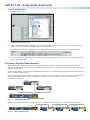
Route Inputs and Outputs:
1. Click the + box next to the input channels (receivers) on another Dante device (DMP128-Rack#1 in the example below).
All device outputs (transmitters) display horizontally.
2. Click the junction of the desired connection
(Example: AXP50-Lecture Hall OUTPUT-01 to DMP128-Rack#1-
DIGITAL_IN-01).
A checkmark at the junction indicates the connection is made. A
checkmark is also placed next to the receiver channel.
NOTE: An input (receiver) can only connect to one output
(transmitter). An output (transmitter) can connect to
multiple inputs (receivers).
3. Click the junction again to disconnect the input from the output.
Additional AXP50CAT outputs (Dante transmitters) connect to or
disconnect from other Dante device inputs (Dante receivers) using the
same method.
See the Dante Controller section of the AXP50 C AT User Guide for information on Dante Controller operation.
AXP50-Lab
AXP50-Lecture Hall
AXP50-ConfRm 01
AXP50-ConfRm 02
AXP50-Podium
DMP128-Rack#1
AXP50-Lab
AXP50-Lecture Hall
AXP50-ConfRm 01
AXP50-ConfRm 02
AXP50-Podium
DMP128-Rack#1
DMP128-Lecture Hall
PRE-OUT-01
DIGITAL_IN-01
DIGITAL_IN-02
DIGITAL_IN-03
DIGITAL_IN-04
DIGITAL_IN-04
DIGITAL_IN-04
PRE-OUT-02
PRE-OUT-03
PRE-OUT-04
PRE-OUT-05
OUTPUT-01
OUTPUT-02
OUTPUT-03
OUTPUT-04
OUTPUT-05
22
DMP128-Lecture Hall
AXP50-Lab
AXP50-Lecture Hall
AXP50-ConfRm 01
AXP50-ConfRm 02
AXP50-Podium
DMP128-Rack#1
AXP50-Lab
AXP50-Lecture Hall
AXP50-ConfRm 01
AXP50-ConfRm 02
AXP50-Podium
DMP128-Rack#1
DMP128-Lecture Hall
PRE-OUT-01
Exp_In-01
Exp_In-02
Exp_In-03
Exp_In-04
DMP128-Rack#2
44
3
3

10
Extron Headquarters
+800.633.9876 Inside USA/Canada Only
Extron USA - West Extron USA - East
+1.714.491.1500 +1.919.850.1000
+1.714.491.1517 FAX +1.919.850.1001 FAX
Extron Europe
+800.3987.6673
Inside Europe Only
+31.33.453.4040
+31.33.453.4050 FAX
Extron Asia
+65.6383.4400
+65.6383.4664 FAX
Extron Japan
+81.3.3511.7655
+81.3.3511.7656 FAX
Extron China
+86.21.3760.1568
+86.21.3760.1566 FAX
Extron Middle East
+971.4.299.1800
+971.4.299.1880 FAX
Extron Korea
+82.2.3444.1571
+82.2.3444.1575 FAX
Extron India
1800.3070.3777
(Inside India Only)
+91.80.3055.3777
+91.80.3055.3737 FAX
© 2014 Extron Electronics All rights reserved. All trademarks mentioned are the property of their respective owners. www.extron.com
68-2251-50 A
07 14
-
 1
1
-
 2
2
-
 3
3
-
 4
4
-
 5
5
-
 6
6
-
 7
7
-
 8
8
-
 9
9
-
 10
10


Extron AXP 50 C AT Manuel utilisateur
- Catégorie
- Matériel musical
- Taper
- Manuel utilisateur
dans d''autres langues
- English: Extron AXP 50 C AT User manual
