
OWNER’S MANUAL
© 2018 Miller Electric Mfg. LLC
FORM: OM-252983E 2018−02
Running Gear, Off-Road (300909)
Running Gear, Off-Road With Never Flatt Tires (300910, 300912)
Running Gear, Multi-Terrain (300913)
Running Gear, Multi-Terrain With Never Flatt Tires (300914)
Running Gear, Multi-Terrain With Protective Cage (300921)
1. Safety Symbol Definitions
DANGER! − Indicates a hazardous situation which, if not
avoided, will result in death or serious injury. The possible
hazards are shown in the adjoining symbols or explained
in the text.
DANGER ! - Indique une situation dangereuse qui, si elle
n’est pas évitée, entraînera la mort ou des blessures
graves. Les éventuels risques sont représentés par les
symboles joints ou expliqués dans le texte.
Fsafe1 2013-10
Beware of electric shock from wiring. Stop engine and
disconnect negative (−) cable from battery before install-
ing this kit. Reinstall all panels and covers.
Attention aux chocs électriques des câbles. Arrêter le
moteur et débrancher le câble négatif de la batterie avant
d’installer cet ensemble. Réinstaller tous les panneaux et
couvercles.
Engsafe1 2013-10
Indicates a hazardous situation which, if not avoided,
could result in death or serious injury. The possible ha-
zards are shown in the adjoining symbols or explained in
the text.
Indique une situation dangereuse qui, si elle n’est pas
évitée, entraînera la mort ou des blessures graves. Les
éventuels risques sont représentés par les symboles
joints ou expliqués dans le texte.
Fsafe2 2013-10
Falling equipment can injure, and damage equipment.
Never put any body part under unit while lifting. Lifting
forks must extend out opposite side of base. Lift and sup-
port unit only with proper equipment and correct proced-
ures. Follow the guidelines in the Applications Manual for
the Revised NIOSH Lifting Equation (Publication No.
94−110) when manually lifting heavy parts or equipment.
La chute de l’équipement peut provoquer des blessures
ou des dommages matériels. Ne jamais mettre une partie
du corps sous l’appareil pendant le levage. Les fourches
de levage doivent ressortir du côté opposé de la base. Ne
soulever l’appareil qu’avec un équipement en bon état
selon les procédures correctes. Suivre les consignes du
Manuel des applications pour l’équation de levage NIOSH
révisée (publication Nº 94–110) lors du levage manuel de
pièces ou équipements lourds.
Fsafe19 2013-10
NOTICE
AVIS
Indicates statements not related to personal injury.
Signale des consignes non associées aux dommages
corporels.
Indicates special instructions.
Fournit des instructions spéciales.
Fsafe3 2013-10
Wear safety glasses with side shields.
Porter des lunettes de sécurité avec écrans latéraux.
Fsafe8 2013-10
CALIFORNIA PROPOSITION 65 WARNINGS
WARNING: Cancer and Reproductive Harm − www.P65Warnings.ca.gov
PROPOSITION CALIFORIENNE 65 AVERTISSEMENTS
AVERTISSEMENT : cancer et troubles de la reproduction − www.P65Warnings.ca.gov.
Fsafe26 2018-01

OM-252983 Page 2
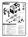
2. Assembling Off-Road Running Gear 300909 Or 300910
Tools Needed:
7/16, 9/16 in.
3/8, 9/16 in.
Description (Qty)
Part
No.
Item
No.
1 252635 Assy, Handle Running Gear (1)
2 252980 Bolt, Crg Stl .250-20 X 1.750 Gr5 Pld Black (4)
3 252634 Bracket, Handle (2)
4 152461 Nut, 250−20 .44hex .23h Stl Pld Sem Cone Wshr .65d (4)
5 604224 Screw, 250−20 x .75 Hexwhd .50d Stl Pld Slffmg Tap−rw (6)
6 601965 Screw, 375−16 x 1.00 Hex Hd−pln Gr5 Pld (4)
7 252631 Rail, Base Support Rh (1)
8 252630 Rail, Base Support Lh (1)
9 602159 Screw, 312−18x .75 Hexwhd.66d Stl Pld Slffmg Tap−Rw (4)
10 167788 Nut, 375−16 .56hex .34h Stl Pld Sem Cone Wshr .88d (4)
11 252981 Axle, Wheel (Large) (2)
12 235794 Wheel, Rbr Tire 14.500 Od X 4.750 Wide X 1.000 Bore (4)
(For 300909)
237725 Wheel, Rbr Never Flat 14.500 Od X 4.750 Wide X 1.00 Bore (4)
(For 300910)
13 602251 Washer, Flat1.062idx2.000odx.134t Stl Pld Ansi 1.00 (4)
14 145665 Ring, Rtng Ext 1.000 Shaft X .052 Thk E Style Pld (4)
15 278065 Rail, Step Bar (Running Gear) (1)
Be sure to provide model when ordering replacement parts.
. Remove paint from axle grooves be-
fore installing retaining rings.
Assembly
Remove and discard existing hardware
from handle attachment points.
Assemble base rails, axles, and wheels
(valve stems out).
Install running gear on unit.
Install step bar on rails.
Attach brackets to handle. Leave loose.
Install handle assembly onto welder/gen-
erator. Tighten hardware.
Grease wheels through fittings.
NOTICE − Never Flat tires have a reduced
load rating. The tire set is sized to support
the unit, fuel, and weld cables only. Addi-
tional weight will damage the tires.
6
10
7
12
13
14
8
253 382
11
3
4
5
2
1
5
15
9
Handle attachment points

OM−252983 Page 3
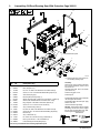
3. Assembling Off-Road Running Gear With Protective Cage 300912
Tools Needed:
7/16, 9/16 in.
3/8, 9/16 in.
Description (Qty)
Part
No.
Item
No.
1 252631 Base, Support Rh (1)
2 252630 Base, Support Lh (1)
3 167788 Nut, 375−16 .56hex .34h Stl Pld Sem Cone Wshr .88d (4)
4 602159 Screw, 312−18x .75 Hexwhd.66d Stl Pld Slffmg Tap−Rw (4)
5 252981 Axle, Wheel (Large) (2)
6 278065 Rail, Step Bar (Running Gear) (1)
7 237725 Wheel, Rbr Never Flat 14.500 Od X 4.750 Wide X 1.00 Bore (4)
8 602251 Washer, Flat1.062idx2.000odx.134t Stl Pld Ansi 1.00 (4)
9 145665 Ring, Rtng Ext 1.000 Shaft X .052 Thk E Style Pld (4)
10 601965 Screw, 375−16 x 1.00 Hex Hd−Pln Gr5 Pld (4)
11 252635 Assy, Handle Running Gear (2)
12 152461 Nut, 250−20 .44hex .23h Stl Pld Sem Cone Wshr .65d (8)
13 604224 Screw, 250−20 x .75 Hexwhd .50d Stl Pld Slffmg Tap−Rw (8)
14 252633 Rail, Side (2)
15 252814 Assy, Cable Holder (4)
16 111998 Pin, Cotter Hair .120 Dia X 2.375lg X .500 Shaft (4)
17 252980 Bolt, Crg Stl .250-20 x 1.750 Gr Pld Black (8)
18 228644 Label, Warning Do Not Lift (Bilingual) (2)
Be sure to provide model when ordering replacement parts.
. Remove paint from axle grooves be-
fore installing retaining rings.
Assembly
Remove and discard existing hardware
from handle attachment points on front
and rear of unit.
Assemble base rails, axles, and wheels
(valve stems out).
Install running gear on unit.
Install step bar.
Install handles and leave loose. Install side
rails and tighten all hardware.
Install cable holders with cotter pins. Apply
labels to side rails.
Grease wheels through fittings.
NOTICE − Never Flat tires have a reduced
load rating. The tire set is sized to support
the unit, fuel, and weld cables only. Addi-
tional weight will damage the tires.
15
14
11
10
2
3
1
5
7
8
9
4
13
253 382
16
12
18
17
6
Handle attachment points

OM-252983 Page 4
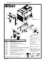
4. Assembling Multi-Terrain Running Gear 300913 Or 300914
Description (Qty)
Part
No.
Item
No.
. Remove paint from axle grooves be-
fore installing retaining rings.
Assembly
Remove and discard existing hardware
from handle attachment points.
Assemble casters to caster mounting
bracket.
Assemble base rails, axle, and wheels
(valve stems out).
Install running gear on unit.
Install caster assembly.
Install handle brackets to handle. Leave
loose.
Install handle on unit and tighten hard-
ware.
Grease wheels through fittings.
NOTICE − Never Flat tires have a reduced
load rating. The tire set is sized to support
the unit, fuel, and weld cables only. Addi-
tional weight will damage the tires.
1 235793 Caster, Swvl 8.00 In Rubber X 2.000 In Wide (2)
2 235791 Bracket, Mtg Caster (1)
3 601965 Screw, 375−16x1.00 Hex Hd−pln Gr5 Pld (12)
4 167788 Nut, 375−16 .56hex .34h Stl Pld Sem Cone Wshr.88d (12)
5 252631 Rail, Base Support Rh (1)
6 252630 Rail, Base Support Lh (1)
7 252981 Axle, Wheel 1in Dia X 30.612 Lg (1)
8 235794 Wheel, Rbr Tire 14.500 Od X 4.750 Wide X 1.000 Bore (2) (For 300913)
237725 Wheel, Rbr Never Flat 14.5 Od X 4.75 Wide X 1” Bore (2) (For 300914)
9 602159 Screw, 312−18x .75 Hex.66d Stl Pld Slffmg Tap (4)
10 602251 Washer, Flat 1.062 Id X 2.0 Od X .134T Stl Pld ANSI 1.00 (2)
11 145665 Ring, Rtng Ext 1.000 Shaft X .085 Thk E Style Pld (2)
12 252635 Assy, Handle Running Gear (1)
13 252634 Bracket, Handle (2)
14 604224 Screw, 250−20x .75 Hexwhd.50d Stl Pld Slffmg Tap (6)
15 152461 Nut, 250−20 .44hex .23h Stl Pld Sem Cone Wshr.65d (4)
16 252980 Bolt, Crg Stl .250-20 x 1.750 Gr Pld Black (4)
Be sure to provide model when ordering replacement parts.
12
3
6
4
5
7
8
10
11
1
3
4
16
14
14
13
9
2
15
Tools Needed:
7/16, 9/16 in. 3/8, 9/16 in.
Handle attachment points

OM−252983 Page 5
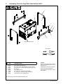
1 252635 Assy, Handle Running Gear (2)
2 152461 Nut, 250−20 .44hex .23h Stl Pld Sem Cone Wshr .65d (8)
3 604224 Screw, 250−20 x .75 Hexwhd .50d Stl Pld Slffmg Tap−rw (8)
4 252633 Rail, Side (2)
5 252814 Assy, Cable Holder (4)
6 252980 Screw, 250−20 x .75 Hexwhd.61d Gr5 Pld (8)
7 111998 Pin, Cotter Hair .120 Dia X 2.375lg X .500 Shaft (4)
8 228644 Label, Warning Do Not Lift (Bilingual) (2)
5. Assembling Protective Cage With Cable Holders 300921
Description (Qty)
Part
No.
Item
No.
Assembly
Remove and discard existing hardware
from handle attachment points on front
and rear of unit.
Install handles. Leave loose. Install cross-
members and tighten all hardware.
Install cable holders with cotter pins. Apply
warning labels.
Be sure to provide model when ordering replacement parts.
5
1
4
3
6
2
8
7
Tools Needed:
7/16, 9/16 in. 3/8, 9/16 in.
Handle attachment points
-
 1
1
-
 2
2
-
 3
3
-
 4
4
-
 5
5


Miller RUNNING GEAR, MULTI-TERRAIN - 300914 Le manuel du propriétaire
- Taper
- Le manuel du propriétaire
- Ce manuel convient également à
dans d''autres langues
Documents connexes
-
Miller RUNNING GEAR PROTECTIVE CAGE Le manuel du propriétaire
-
-
Miller MH000000 Le manuel du propriétaire
-
-
-
-
-
-
-