GO10SW
GO12SW
Outdoor
Underground
Subwoofers
arden
asis
OWNER’S MANUAL
GO10SW
GO12SW

1 | EN MAN0140 | 020917

2EN |
TABLE OF CONTENTS
Overview ........................................ 3
Subwoofer.....................................3
Required Tools .................................3
Power ........................................3
Planning The Install ..............................4
Installation Considerations ........................ 5
Digging the Hole..................................5
Subwoofer Assembly..............................6
Subwoofer Positioning ............................6
Cable Recommendations ..........................7
Wiring & Subwoofer Installation ....................8
Mono Setup Using 4 Conductor Burial Cable
& Crown Amplifier ..............................8
Preparing the 4 Conductor Burial Cable ............8
Subwoofer & Burial Cable Connections.............9
Test System .....................................9
To Avoid Subwoofer Damage ......................10
Listening Outdoors ..............................10
Audio Settings Chart .............................11
Limited Warranty................................12

3 | EN
Subwoofer
The Garden Oasis Series Subwoofers are weatherproof
and designed to be buried at a depth of 2 feet. Ideal for
backyards ranging from 2,000 to 3,000 sq feet, the use of
multiple subwoofers is recommended for larger sized yards.
Made of durable ABS plastic, the subwoofer can endure
the elements while providing years of trouble free service.
While installation is relatively easy, Paradigm’s Garden
Oasis series is designed to be installed by your authorized
Paradigm dealer.
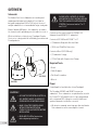
WARNING!
• ACCOUNT FOR POTENTIAL ELECTRICAL,
GAS, BURIED CABLES, PLUMBING OR
OTHER OBSTACLES BEFORE DIGGING.
• MANY LOCALITIES FORBID DIGGING
WITHOUT PRIOR NOTIFICATION.
CONTACT LOCAL AUTHORITIES BEFORE
INSTALLATION.
• READ AND FOLLOW all instructions
before beginning installation.
PLEASE NOTE: CONTENTS OF GOSW12
ARE SHIPPED IN TWO CARTONS. ENSURE
THAT YOU HAVE BOTH CARTONS BEFORE
STARTING. Cartons are labeled “1 of 2”
and “2 of 2”.
Contents are the same for both the GOSW10 (10”
Subwoofer) and GOSW12 (12” subwoofer).
Contents of GO10SW and GO12SW “1 of 2”
• (1)Subwoofer Body with Attached Cable
• (2) Silicone-Filled Wire Connectors
Contents of Box 2 (GO12SW only)
• (1) Subwoofer Canopy
• (1) Port Tube with Compression Clamps
Required Tools:
• Shovel
• Cable Strippers
• Flat Head Screwdriver
• Wrench
Power
Crown Amplifier (available direct from Paradigm).
The Paradigm GOSW10 and GOSW12 are passive
subwoofers. These subwoofers are optimized for use with
the Crown CDi 1000 amplifier which is pre-programmed
with customized DSP settings for a variety of different
speaker/subwoofer installation scenarios.
• We do not recommend connecting more than two Garden
Oasis subwoofers on the same amplifier channel.
OVERVIEW
GO10SW
GO12SW

4EN |
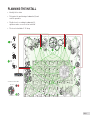
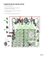
PLANNING THE INSTALL
• Identify the location.
• Determine the positioning of subwoofer(s) and
satellite speakers.
• Dig the trench according to subwoofer(s),
speakers and accessories to be installed.
• The trench should be 6”-8” deep.
=
=
GO4
GO6
GO10SW
GO12SW
or
or
Crown Amplifier
4 Conductor Burial Wire
Subwoofer
Speakers
–
+
–
+
Black Red
Green White
+
–
–
+

5 | EN
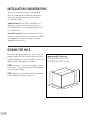
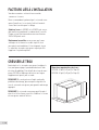
Before placing the heavy subwoofer in the hole, you can
gauge the depth of the hole using the packing carton. For
the GO12SW subwoofer carton, remember to allow for the
additional width taken up by the port elbow.
NOTE! In areas where clay or minor drainage issues are
present, place 1” of pea gravel underneath the subwoofer
to ensure proper drainage.
NOTE! Subwoofer can be positioned and operated above
ground. Stabilize the subwoofer before use.
DIGGING THE HOLE
Approximate Hole Dimensions:
GO10SW: 26”(W) x 20”(L) x 18”(H)
GO12SW: 30”(W) x 25”(L) x 24”(H)
(H)
(W)
(L)
16”
16”
32”
5”
There a few considerations before you start digging.
We also recommend that the Subwoofer (paired with
speakers) be tested before any trenches are dug to
accommodate wiring.
Optimize Sound: Both the GOSW10 and GOSW12 are
designed to greatly enhance speaker performance.
Each sub will perform in an area of approximately 2,000
to 3,000 square feet.
Accessible Location: Ensure that the proposed area is
easily accessed and that the area is not prone to flooding
or standing water or where the canopy can be easily
damaged, kicked or struck.
INSTALLATION CONSIDERATIONS

6EN |
GO10SW
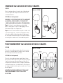
Place the subwoofer into the hole, ensure there is
approximately 5” between the ground level and the
bottom of the canopy.
GO12SW (See diagram)
Place the assembled subwoofer into the hole, then rotate
the subwoofer cabinet until there is approximately 5”
between the ground level and the bottom of the canopy.
Once the positioning of the subwoofer is satisfactory,
tighten the compression clamp that holds the elbow port
to the subwoofer.
IMPORTANT! DO NOT BACKFILL HOLE UNTIL YOUR
SYSTEM IS FULLY WIRED/TESTED.
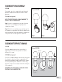
GO10SW
To assemble, place the canopy into the port tube and
tighten the compression clamp so to ensure a water
tight seal.
GO12SW (See diagram)
NOTE: THE PORT ELBOW IS CLEARLY MARKED “TO
CANOPY” AND “TO SUBWOOFER”.
Step 1: Insert the canopy onto the one end of the port
elbow until it is seated properly. Fully tighten the
compression clamp.
Step 2: Attach the assembled canopy and elbow port to
the subwoofer, ensuring that dirt and other debris do not
enter the port tube. Do not fully tighten the compression
clamp that holds the elbow port to the subwoofer.
Shown: GO12SW
SUBWOOFER ASSEMBLY
SUBWOOFER POSITIONING
Approximate Hole Dimensions:
GO10SW: 26”(W) x 20”(L) x 18”(H)
GO12SW: 30”(W) x 25”(L) x 24”(H)
Ground
Level
Example 1
Example 2
Example 3
5”
16”
16”
32”
16”
16”
32”
Shown: GO12SW
Step 1 Step 2

7 | EN
We strongly recommend using burial–rated cable
(not included) when installing any of the Garden Oasis
Subwoofers. In addition, it’s critical to use the proper cable
gauge. Please review the chart below.
We do not recommend use of smaller wire gauges, as
performance will be compromised.
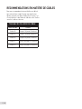
CABLE RECOMMENDATIONS
CABLE GAUGE CHART
WIRE Gauge DISTANCE
18 Gauge Up to 100 feet (30 meters)
16 Gauge Up to 150 feet (45 meters)
14 Gauge Up to 200 feet (61 meters)
12 Gauge Up to 400 feet (122 meters)
10 Gauge Up to 650 feet (198 meters)

8EN |
Mono Setup Using 4 Conductor Burial Cable & Crown Amplifier
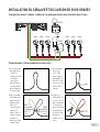
Preparing the 4 Conductor Burial Cable
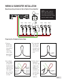
WIRING & SUBWOOFER INSTALLATION
1. Starting
with the first
speaker and
every speaker/
sub that
comes after,
create a loop
approximately
6” in length.
3. Use a Round
Cable Stripper
to remove the
outside protective
cable jacket to
expose the four
color-coded
wires. Separate
the wire loops
as shown.
2. Recommended:
Use a wire tie
(not included)
to keep the wire
loop intact and
act as a strain
relief.
Wires for
Subwoofer
white (+) &
green (-)
Wires for
Speaker
red (+) &
black (-)
Mono Mono Mono MonoMono Mono
GOSW12
GOSW10
OR
NOTE: If using 4 conductor
burial cable, cap any loose
wires at the the last speaker
installed to avoid short out and
potential amplifier damage.
4. Cut the white (+)
and green (-)
wires with cable
strippers and
strip off 1 inch
(25.4mm) of
insulation from
the ends of the
wires to expose
the copper
conductor.

9 | EN
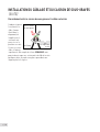
TEST SYSTEM
After all subwoofer and satellites connections are
completed, connect the wires to your receiver or amplifier.
IMPORTANT: Be sure not to let any stray’+’ and’-’ strands
touch each other. Touching strands will cause a short
circuit which could damage your amplifier.
Turn your receiver or amplifier ‘On’ and test the system with
your favorite music. If the subwoofer is operating properly,
refill the wire trench and enjoy your new subwoofer.
Subwoofer & Burial Cable Connections
To Subwoofer
To Amp
To Adjoining
Speaker
Combine and twist
(clockwise) the
wires (as shown
in the diagram)
from the amp,
subwoofer and to
the neighboring
speaker. Secure
these three wires
using the provided
Silicone Filled
Wire Caps. NOTE: You may have to cut some of the
speaker cable emanating from the subwoofer to a more
manageable size.
WIRING & SUBWOOFER INSTALLATION (CONT’D)

10EN |
Don’t be fooled by your amplifier’s volume control. It
adjusts listening level—it does not indicate power output.
If your subwoofer begins to sound harsh or grating, or
if you hear the bass breaking up, turn the volume down
immediately or you will damage your subwoofer(s)! This
type of damage constitutes abuse and is not covered by
the warranty!
Tone controls and equalizers can demand even more
power from an amplifier, lowering the point at which it
produces clipping distortion. Use them sparingly, if at all,
and do not use them when listening at loud levels.
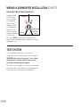
Outdoors there are no walls to contain sound. Background
noise is louder and the distance listeners are from the
subwoofer(s) is usually greater. Achieving a reasonable
listening level can be more difficult. The tendency is to
turn up the volume, however this may disturb neighbors
and when turned up too high, can seriously damage the
subwoofer(s) or your amplifier.
The solution? In larger areas we recommend using
multiple Paradigm Garden Oasis subwoofers.
Demand on the amplifier is reduced and neighbors are
not disturbed. Think of it this way: When lighting a large
outdoor area, using multiple floodlights on a dimmer set
to a low setting is far more effective than using a single
floodlight with the dimmer set to high.
TO AVOID SUBWOOFER DAMAGE
LISTENING OUTDOORS

11 | EN
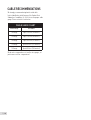
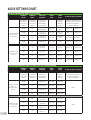
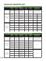
AUDIO SETTINGS CHART
INSTALLATION USING LONG WIRES (100 feet or longer)
CHANNEL #1
ON AMP
CHANNEL #2
ON AMP
PRESETS ON
CROWN AMP
PRESET
NAME
POWER
OUTPUT
SET DIAL ON SATELLITE SPEAKER
Wire Product
to Channel #1
on the Crown
Amplifier
Wire Product
to Channel #2
on the Crown
Amplifier
Select the Preset
number on the
Crown Amplifier
specified below
Signal level
provided to
subwoofer /
speakers
Remove the cap from the rear of
the satellite speaker and position
the dial to the appropriate
wattage setting below
GO10SW or GO12SW
plus GO4 or GO6
satellite speakers
GO10SW GO4
Preset 2 for
GO10SW and GO4
GO4_10SW
8 ohm / 70V
hybrid
Speakers: 1-12 30W (or less)
GO10SW GO6
Preset 3 for
GO10SW and GO6
GO6_10SW
8 ohm / 70V
hybrid
Speakers: 13-24 15W (or less)
GO12SW GO4
Preset 4 for
GO12SW and GO4
GO4_12SW
8 ohm / 70V
hybrid
Speakers: 25-50 7.5W (or less)
GO12SW GO6
Preset 5 for
GO12SW and GO6
GO6_12SW
8 ohm / 70V
hybrid
Speakers: 50-100 3.8W (or less)
NO subwoofer and
GO4 or GO6 satellite
speakers
GO4 GO4
Preset 10 for
GO4 in Mono
GO_4_MO NA / 70V Speakers: 1-12 30W (or less)
GO6 GO6
Preset 11 for
G06 in Mono
GO_6_MO NA / 70V Speakers: 13-24 15W (or less)
GO4 GO4
Preset 12 for
GO4 in Stereo
GO_4_ST NA / 70V Speakers: 25-50 7.5W (or less)
GO6 GO6
Per-set 13 for
GO6 in Stereo
GO_6_ST NA / 70V Speakers: 50-100 3.8W (or less)
INSTALLATION USING SHORT WIRES (less than 100 feet) FOR 4 OR LESS SPEAKERS
CHANNEL #1
ON AMP
CHANNEL #2
ON AMP
PRESETS ON
CROWN AMP
PRESET
NAME
POWER
OUTPUT
SET DIAL ON SATELLITE SPEAKER
Wire Product
to Channel #1
on the Crown
Amplifier
Wire Product
to Channel #2
on the Crown
Amplifier
Select the Preset
number on the
Crown Amplifier
specified below
Signal level
provided to
subwoofer /
speakers
Remove the cap from the rear of
the satellite speaker and position
the dial to the appropriate
wattage setting below
GO10SW or GO12SW
plus 4 or less
GO4 or GO6 satellite
speakers
GO10SW GO4
Preset 6 for
GO10SW and GO4
8GO410SW 8 ohm / 8ohm
8ohms
GO10SW GO6
Preset 7 for
GO10SW and GO 6
8GO610SW 8 ohm / 8ohm
GO12SW GO4
Preset 8 for
GO12SW and GO4
8GO412SW 8 ohm / 8ohm
GO12SW GO6
Preset 9 for
GO12SW and GO6
8GO612SW 8 ohm / 8ohm
No Subwoofer and 4
or less GO4 or GO6
satellite speakers
GO4 GO4
Preset 14 for
GO4 in mono
8GO_4_MO NA / 8ohm
8ohms
GO6 GO6
Preset 15 for
GO6 in mono
8GO_6_MO NA / 8ohm
GO4 GO4
Preset 16 for
GO4 in stereo
8GO_4_ST NA / 8ohm
GO6 GO6
Preset 17 for
GO6 in stereo
8GO_6_ST NA / 8ohm

12EN |
Paradigm
®
Garden Oasis
™
subwoofers are warranted to
be and remain free of manufacturing and/or material
defects for a period of three (3) years from the date of
original purchase. Within the time period specified, repair,
replacement or adjustment of parts for manufacturing
and/or material defects will be free of charge to the
original owner. Thermal or mechanical abuse/misuse is
not covered under warranty.
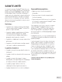
Limitations:
• Warranty begins on date of original retail purchase
from an Authorized Paradigm
®
Dealer only. It is not
transferable.
• Warranty applies to product in normal residential use
only. If product is subjected to any of the conditions
outlined in the next section, warranty is void.
• Warranty does not apply if the product is used in
professional or commercial applications.
• Warranty also excludes normal cosmetic deterioration
caused by environmental conditions.
Warranty is Void if:
• The product has been abused (intentionally or
accidentally).
• The product has been used in conjunction with
unsuitable or faulty equipment.
• The product has been subjected to damaging signals,
derangement in transport, mechanical damage or any
other other conditions.
• The product (including cabinet) has been tampered with
or damaged by an unauthorized service facility.
• The serial number has been removed or defaced.
Owner Responsibilities:
• Provide normal/reasonable operating care and
maintenance.
• Provide or pay for transportation charges for product to
service facility.
• Provide proof of purchase (your sales receipt given
at time of purchase from your Authorized Paradigm
®
Dealer must be retained for proof-of-purchase date).
Should servicing be required, contact your nearest
Authorized Paradigm
®
Dealer, Paradigm Electronics Inc.
or Import Distributor (outside the U.S. and Canada) to
arrange, bring in or ship prepaid, any defective unit. Visit
our website, www.paradigm.com for more information.
Paradigm Electronics Inc. reserves the right to improve
the design of any product without assuming any
obligation to modify any product previously manufactured.
This warranty is in lieu of all other warranties expressed
or implied, of merchantability, fitness for any particular
purpose and may not be extended or enlarged by anyone.
In no event shall Paradigm Electronics Inc., their agents
or representatives be responsible for any incidental or
consequential damages. Some jurisdictions do not allow
limitation of incidental or consequential damages, so this
exclusion may not apply to you.
Retain this manual and your sales receipt for proof of
warranty term and proof of purchase.
LIMITED WARRANTY

13 | EN
NOTES

GO10SW
GO12SW
Caissons de sous-graves
souterrains extérieurs
arden
asis
MANUEL DE
L’ UTILISATEUR
GO10SW
GO12SW

1 | FR MAN0140 | 020917

2FR |
TABLES DES MATIÈRES
Aperçu..........................................3
Caisson de sous-graves .........................3
Outils nécessaires ..............................3
Alimentation...................................3
Planification de l’installation ......................4
Facteurs liés à l’installation........................ 5
Creuser le trou................................... 5
Montage du caisson de sous-graves ................. 6
Positionnement du caisson de sous-graves ..........6
Recommandations en matière de câbles ............. 7
Installation du câblage et du caisson de sous-graves . .8
Configuration mono à l’aide de 4 câbles de
raccordement souterrains et amplificateur Crown ...8
Préparation des 4 câbles de
raccordement souterrains .......................8
Subwoofer & Burial Cable Connections.............9
Tester le système ................................9
Pour éviter les dommages au caisson de sous-graves . .10
Écoute à l’extérieur..............................10
Tableau des paramètres audio.....................11
Limited Warranty................................12

3 | FR
Caisson de sous-graves
Les caissons de sous-graves de la série Garden Oasis
résistent aux intempéries et sont conçus pour être enterrés
à une profondeur de deux pieds. Ils sont parfaits pour les
jardins de 2000 à 3000 pieds carrés; il est recommandé
d’utiliser plusieurs caissons de sous-graves pour les jardins
plus grands.
Fait de plastique ABS durable, le caisson de sous-graves
Oasis peut résister aux éléments tout en offrant des années
de fonctionnement sans tracas.
Bien que l’installation soit relativement facile, les produits
de la série Garden Oasis de Paradigm sont conçus pour être
installés par votre revendeur Paradigm autorisé.
MISE EN GARDE!
• TENEZ COMPTE DES FILS ÉLECTRIQUES,
DES CONDUITES DE GAZ, DES
CÂBLES SOUTERRAINS, DES TUYAUX
DE PLOMBERIE ET DES AUTRES
OBSTACLES AVANT DE CREUSER.
• DE NOMBREUSES LOCALITÉS
INTERDISENT DE CREUSER SANS
PRÉAVIS. COMMUNIQUEZ AVEC
LES AUTORITÉS LOCALES AVANT
L’INSTALLATION.
• VEUILLEZ LIRE ET SUIVRE toutes les
instructions avant de commencer
l’installation.
• VEUILLEZ NOTER : LE CONTENU DU
GOSW12 EST ENVOYÉ DANS DEUX
BOÎTES. ASSUREZ-VOUS D’AVOIR LES
DEUX BOÎTES AVANT DE COMMENCER.
Les boîtes sont étiquetées « 1 de 2 » et «
2 de 2 ».
Le contenu est le même pour le GOSW10 (caisson de
sous-graves de 10 po) et le GOSW12 (caisson de sous-
graves de 12 po).
Contenu du GO10SW et du GO12SW « 1 de 2 »
• (1) Boîtier de caisson de sous-graves avec câble fixé
• (2) Connecteurs de câble remplis de silicone
Contenu de la boîte 2 (GO12SW uniquement)
• (1) Couvert de caisson de sous-graves
• (1) Tube de port avec pinces de compression
Outils nécessaires :
• Pelle • Pinces à dénuder
• Tournevis à tête plate • Clé
Alimentation
Amplificateur Crown (disponible directement de Paradigm).
Les caissons de sous-graves GOSW10 et GOSW12 de
Paradigm sont passifs. Ces caissons de sous-graves
sont optimisés pour une utilisation avec l’amplificateur
Crown CDi 1000 qui est préprogrammé avec des
paramètres DSP sur mesure pour différents scénarios
d’installation d’enceintes/caissons de sous-graves.
Nous recommandons de ne pas raccorder plus de deux
caissons de sous-graves Garden Oasis sur le même canal
d’amplificateur.
APERÇU
GO10SW GO12SW

4FR |
PLANIFICATION DE L’INSTALLATION
=
=
GO4
GO6
GO10SW
GO12SW
–
+
–
+
+
–
ou
ou
Amplificateur Crown
4 câbles conducteurs
souterrains
Caisson de
sous-graves
Enceintes
Noir Rouge
Vert Blanc
–
+
• Déterminez l’emplacement.
• Déterminez le positionnement du caisson de sous-
graves et des enceintes satellites.
• Creusez la tranchée en fonction des enceintes et des
accessoires à installer.
• La tranchée doit avoir une profondeur de 6 à 8 po.

5 | EN
Avant de placer le caisson de sous-graves lourd dans le
trou, vous pouvez jauger la profondeur du trou à l’aide
du carton d’emballage. Pour la boîte du caisson de sous-
graves GO12SW, n’oubliez pas de laisser une largeur
supplémentaire pour le port en coude.
REMARQUE! En cas de présence d’argile ou de petits
problèmes de drainage, placez un pouce de gravier fin
sous le caisson de sous-graves pour garantir un drainage
approprié.
REMARQUE! Le caisson de sous-graves peut être placé
dans le sol et fonctionner sous terre. Stabilisez le caisson
de sous-graves avant de l’utiliser.
CREUSER LE TROU
Vous devez examiner certains facteurs avant de
commencer à creuser.
Nous recommandons également que le caisson de sous-
graves (jumelé avec les enceintes) soit testé avant de
creuser des tranchées pour le câblage.
Optimiser le son : le GOSW10 et le GOSW12 sont conçus
pour améliorer grandement le rendement de l’enceinte.
Chaque caisson fonctionnera dans une zone d’environ
2000 à 3000 pieds carrés.
Emplacement accessible : assurez-vous que la zone
envisagée est facilement accessible et qu’elle n’est
pas exposée aux inondations, à l’eau stagnante, et que
le couvert du caisson de sous-graves ne peut pas être
frappé avec les pieds ou piétiné.
FACTEURS LIÉS À L’INSTALLATION
(h)
(l)
(L)
16”
16”
32”
5”
Dimensions approximatives des trous :
GO10SW : 26 po (L) x 20 po (l) x 18 po (h)
GO12SW : 30 po (L) x 25 po (l) x 24 po (h)
La page est en cours de chargement...
La page est en cours de chargement...
La page est en cours de chargement...
La page est en cours de chargement...
La page est en cours de chargement...
La page est en cours de chargement...
La page est en cours de chargement...
La page est en cours de chargement...
-
 1
1
-
 2
2
-
 3
3
-
 4
4
-
 5
5
-
 6
6
-
 7
7
-
 8
8
-
 9
9
-
 10
10
-
 11
11
-
 12
12
-
 13
13
-
 14
14
-
 15
15
-
 16
16
-
 17
17
-
 18
18
-
 19
19
-
 20
20
-
 21
21
-
 22
22
-
 23
23
-
 24
24
-
 25
25
-
 26
26
-
 27
27
-
 28
28


Paradigm GO12SW Manuel utilisateur
- Taper
- Manuel utilisateur
- Ce manuel convient également à
dans d''autres langues
- English: Paradigm GO12SW User manual
Documents connexes
-
Paradigm Monitor SUB 12 Le manuel du propriétaire
-
-
Paradigm X-300 Manuel utilisateur
-
-
Paradigm Defiance X15 Manuel utilisateur
-
-