Rev-A-Shelf 4WCTM-18DM2-175 Mode d'emploi
- Taper
- Mode d'emploi

1
12400 Earl Jones Way
Louisville, KY 40299
rev-a-shelf.com
800-626-1126
TOP MOUNT PULL-OUT WASTE CONTAINERS
4WCTM-12DM1, 4WCTM-15DM2, 4WCTM-18DM2 AND 4WCTM-27-4
TOOLS REQUIRED:
30-45 MIN
ESTIMATED ASSEMBLY TIME:
CARE AND MAINTENANCE:
Clean with a damp cloth and
wipe parts dry.
I-WCTM150SH-TRI-1115
1
4
1
8
1
16
3
8
3
32
7
64
#2 #1
5
16
5
8
1
2
3
8
2” 1”
90˚
CABINET PREPARATION
1
4
1
8
1
16
3
8
3
32
7
64
#2 #1
5
16
5
8
1
2
3
8
2” 1”
90˚
1
4
1
8
1
16
3
8
3
32
7
64
#2 #1
5
16
5
8
1
2
3
8
2” 1”
90˚
1
4
1
8
1
16
3
8
3
32
7
64
#2 #1
5
16
5
8
1
2
3
8
2” 1”
90˚
#2
#2
#2
If the back wall of your cabinet
is thinner than ½” (13 mm), you
will need to install furring strips
to attach the rear slide brack-
et. If your cabinet back wall is
½” (13 mm) or thicker, skip to
step 1.
A) Cut (2) furring strips to ½”
(13 mm) thick, 3” (76 mm) wide
and a minimum of 4” (102 mm)
long.
B) Install furring strips to both
sides of your cabinet as shown.
(No fasteners are provided for
this step.) See Fig. A
1-3/4” (45 mm)
14-1/4” 362 mm)
FIG. A
1
4
1
8
1
16
3
8
3
32
7
64
#2 #1
5
16
5
8
1
2
3
8
2” 1”
90˚
#2
#2
#2
Description QTY.
Wood Frame w/ Slides & Door Mount Brackets 1
Waste Container 1 or 2 (depending on unit purchased)
Rear Plastic Bin 1 (not included on all units)
Door Mount Screws 6
Rear Socket and slide attachment screws 6
Double Stick Tape Pieces 2
PARTS LIST:
4WCTM-12DM1

800-626-1126 | rev-a-shelf.com
2
Pull slides away from wood
frame until they stop. Press the
black lever in the middle of the
slide to the opposite side and
pull slide to disconnect. (It may
take a little force to pull apart.)
See Fig. B
STEP 1
Install rear brackets to the
outer member of the slides
that you just removed. Make
sure the bend is facing the
inside of the slide as shown.
See Fig. C
STEP 2
FIG. C
Measure the distance from the
inside wall of your cabinet to
the opening and record. ((A) in
Fig. D)) You will need this num-
ber for step 6.
STEP 3
FIG. B
I-WCTMBBSC150-0315
INSTALLATION
INSTRUCTIONS
Top Mount Pull-Out Waste Containers
For models: 4WCTM-12BBSCDM1, 4WCTM-15BBSCDM2,
4WCTM-18BBSCDM2, 4WCTM-1550BBSCDM-1
and 4WCTM-2150BBSCDM-2
TOOLS REQUIRED:
ESTIMATED ASSEMBLY
TIME:
45 MIN
CARE AND MAINTENANCE:
CLEAN WITH A DAMP CLOTH
AND WIPE PARTS DRY.
WOVEN BASKET INSTALLATION INSTRUCTIONS
ESTIMATED ASSEMBLY TIME:
20 MIN
CARE AND MAINTENANCE:
Clean basket and wood frame with a damp cloth and wipe parts
dry. Machine wash liner in cold water with like colors.
2409 Plantside Dr., Jeersontown, KY 40299
800.626.1126
www.rev-a-shelf.com
1) Measure the inside cabinet width (ICW) at desired height for wood rails.
2) Measure the width of basket wood frame (BW).
3) Subtract BW from ICW. Divide answer by 2. Subtract 1/16” from answer.
This will give you the dimension needed from bottom of groove to back of wood
rail (ICW-BW) ÷ 2 - 1/16”.
4) Cut wood rails per steps 1-3.
5) Place rst cut rail in cabinet with front of rail against back of face frame (for
frameless cabinets, ush with front of cabinet.) at desired height. Secure the front
hole with proper size screw. (Screws not included due to variant in cabinet wall
thicknesses) (Make sure screw does not go through outside wall of cabinet).
Part list:
NOTE: SCREWS NOT INCLUDED DUE TO VARIANT SIZES IN CABINETS
(ICW-BW) ÷ 2 - 1/16”
Desired Height
of Rail
Inside
Cabinet
Width
(ICW)
Basket
Width
(BW)
Bottom of groove
Back of wood rail
8) Install second rail on opposite side of cabinet per steps 5-6 at height
location from step 7.
7) Measure from oor of cabinet to bottom of installed rail.
6) Make sure rail is level, then secure to cabinet with screws at
remaining hole locations.
9) Slide in basket.
I-4WV-TRI-1013
Bottom of
rail to oor of
cabinet
Repeat steps for additional baskets.
Visit our YouTube Channel for an installation video of this product
Youtube.com/REVASHELF nd “Wood Top Mount”
1/16”
12400 Earl Jones Way, Louisville, KY 40299
(800) 626-1126 • www.rev-a-shelf.com
Step1: Install rear bracket to rear of slide.
19” 19”
INSTALLATION INSTRUCTIONS
for Top Mount Pull-Out Waste Containers
INSTRUCCIONES DE INSTALACIÓN
para cestos de basura deslizantes con montaje superior
NOTICE D’INSTALLATION
de la poubelle montée sur glissières supérieures
For models, Para los modelos, Pour les modèles:
4WCTM-12BBSCDM1, 4WCTM-15BBSCDM2,
4WCTM-18BBSCDM2, 4WCTM-1550BBSCDM-1
and 4WCTM-2150BBSCDM-2
Step 2:
Paso 2: Instale la parte delantera de la deslizadera en el bastidor
Étape 2: Monter l’avant de la glissière sur le cadre frontal. Le trou doit se
Step 5: Mount Rear Bracket. Extend the slide rear mounting bracket until it
cabinet wall at rear of slide as it is up front.
tighten. Tighten screw in front
bracket.
Paso 5: Monte el soporte trasero. Extienda el soporte trasero de la
deslizadera hasta que toque atrás (el listón trasero). La parte inferior de
distancia entre la parte posterior de la pared del
soporte de montaje trasero debe ser similar a la
frente. Introduzca el tornillo de montaje en la
el centro del soporte de montaje trasero y
soporte delantero.
Étape 5: Monter le support arrière. Étendre le support de montage arrière
de la glissière jusqu’à ce qu’il touche l’arrière (le tasseau). Le dessous de la
séparant le
support de montage arrière
Placer une vis de montage dans la fente
horizontale du centre du support
de montage arrière et la serrer. Serrer la vis du support avant.
Step 6: Install wood unit (with slides attached) into cabinet, engaging
product member slides into cabinet member slides push unit until it locks
in place.
Paso 6: Instale la pieza de madera (con las deslizaderas instaladas) en
el armario de forma que las deslizaderas en el producto se entren en las
deslizaderas que están en el
armario y empuje hasta que cierren.
Étape 6: Installer l’ensemble en bois (avec les glissières
montées) dans l’armoire en engageant les glissières du produit dans celles
de l’armoire. Pousser sur l’ensemble jusqu’à ce qu’il s’enclenche.
Step 1: Install rear bracket to rear of slide.
Paso 1: Instale el soporte trasero en la parte posterior de la deslizadera.
Étape 1: Attacher le support arrière à l’arrière de la glissière.
STEP 4:
Measure from inside
cabinet wall to inside
face frame (A) distance
should be measured
the same at rear of
cabinet (B).
STEP 6:
Install wood unit (with slides attached) into cabinet,
engaging product member slides into cabinet member
slides, push
unit until it
locks in place.
Now you are
ready to
mount the
door.
STEP 7:
See door mounting instructions on inside.
STEP 5:
Position the slide with front
bracket on the face frame
opening and move it forward
until the self register stop hits the
inside of the face frame opening.
Bottom of slide should be 13 1/2"
from cabinet floor. Install screw in
slotted mounting hole, do not
tighten. Extend the slide rear mounting bracket until it
contacts the rear Furring strip. Bottom of slide should be
13 1/2" from cabinet floor. Rear mounting bracket should
be the same distance from the side cabinet wall at rear of
slide as it is up front. Drive mounting screw in center
horizontal slot of rear mounting bracket, tighten.
Tighten screw in front bracket.
Face Frame
Cabinet Member
Slides
Furring Strips
Product Member Cabinet Member
Self
Register
Stop
Front View
(B)
Step 3: If rear of cabinet is thinner than ½”, install a ½” x 3” wide furring
Paso 3: Si el grosor de la parte trasera del armario es inferior a
13 mm (½ pulg.), instale un listón de
13 x 76 mm (½ x 3 pulg.) de ancho
centrada en la parte trasera y a 36cm
(14 ¼
pulg. - 35 y 27Qt. / 20 ⁄ - 50Qt.) del
Étape 3: Si l’arrière de l’armoire est
moins épais que 13 mm (½ po),
attacher un tasseau de
13mm x 76mm (½ x 3 po) à l’arrière de l’armoire,
centré à 36 cm (14-¼
po. - 33 et 25(L) / 20- ⁄ po. - 47(L)) du fond de l’armoire.
Step 4: Measure from inside cabinet wall to inside face frame (A) distance
should be measured the same at rear of cabinet (B).
Paso 4: La medida de la pared interior del
STEP 1:
Install front bracket to
front side of slide.
STEP 2:
Install rear bracket to
rear of slide.
STEP 3:
Mount slide to cabinet
if rear of cabinet is
thinner then 1/2" install
a 1/2" x 3" wide furring
strip to the back of the
cabinet centered
14 1/4" from floor of
cabinet.
STEP 4:
Measure from inside
cabinet wall to inside
face frame (A) distance
should be measured
the same at rear of
cabinet (B).
STEP 6:
Install wood unit (with slides attached) into cabinet,
engaging product member slides into cabinet member
slides, push
unit until it
locks in place.
Now you are
ready to
mount the
door.
STEP 7:
See door mounting instructions on inside.
14
1
/4"
13
1
/2"
STEP 5:
Position the slide with front
bracket on the face frame
opening and move it forward
until the self register stop hits the
inside of the face frame opening.
Bottom of slide should be 13 1/2"
from cabinet floor. Install screw in
slotted mounting hole, do not
tighten. Extend the slide rear mounting bracket until it
contacts the rear Furring strip. Bottom of slide should be
13 1/2" from cabinet floor. Rear mounting bracket should
be the same distance from the side cabinet wall at rear of
slide as it is up front. Drive mounting screw in center
horizontal slot of rear mounting bracket, tighten.
Tighten screw in front bracket.
Face Frame
Cabinet Member
Slides
Furring Strips
Furring
Strips
Product Member Cabinet Member
Self
Register
Stop
14
1
/4"
13
1
/2" 13
1
/2"
Front View
Top View
(A)
(B)
armario a la parte
interior del bastidor delantero
(A) debe ser similar en la parte
posterior del armario (B).
Étape 4: Mesurer à partir
de la paroi intérieure de
l’armoire jusqu’à l’intérieur du
cadre frontal (A). Mesurer la
même distance à l’arrière de
l’armoire (B).
14¼”
Face Frame
12¾”
14¼”
- 35Qt. & 27Qt. / 19” - 50Qt.
-
35 y 27Qt. / 19” -
50Qt.
- 35 y 27Qt./ 19”-50Qt.)
e
e
(
- 35Qt. & 27Qt. / 20 ⁄ - 50Qt.
(
13 ⁄ ” - 35 & 27Qt.
-
19” - 50Qt. g
Drive mounting screw in center
horizontal slot of rear mounting bracket,
ce
de la paroi latérale de l’armoire doit être identique à l’arrière et à l’avant.
c
d
g
Step 7: Mount Door...See separate instructions sheet included.
Paso 7: Monte la puerta de acuerdo a las instrucciones que están en el
instructivo separado adjunto.
Étape 7: Montage de la porte : voir la notice de montage séparée.
I-WCTMBBSC150-0115
27Qt./
35Qt.
50Qt.
piso del armario.
armario a la deslizadera del
que tiene con respecto al
ranura horizontal que está en
apriételo. Apriete el tornillo en el
. - 33 et 25(L) / 19” po. - 47(L))
. - 33 et 25 (L) / 19 po.-
47(L))
(
(
(
(
(
f
12400 Earl Jones Way, Louisville, KY 40299
(800) 626-1126 • www.rev-a-shelf.com
19” 19”
INSTALLATION INSTRUCTIONS
for Top Mount Pull-Out Waste Containers
INSTRUCCIONES DE INSTALACIÓN
para cestos de basura deslizantes con montaje superior
NOTICE D’INSTALLATION
de la poubelle montée sur glissières supérieures
For models, Para los modelos, Pour les modèles:
4WCTM-12BBSCDM1, 4WCTM-15BBSCDM2,
4WCTM-18BBSCDM2, 4WCTM-1550BBSCDM-1
and 4WCTM-2150BBSCDM-2
Step 2:
Paso 2: Instale la parte delantera de la deslizadera en el bastidor
Étape 2: Monter l’avant de la glissière sur le cadre frontal. Le trou doit se
Step 5:
Mount Rear Bracket. Extend the slide rear mounting bracket until it
cabinet wall at rear of slide as it is up front.
tighten. Tighten screw in front
bracket.
Paso 5: Monte el soporte trasero. Extienda el soporte trasero de la
deslizadera hasta que toque atrás (el listón trasero). La parte inferior de
distancia entre la parte posterior de la pared del
soporte de montaje trasero debe ser similar a la
frente. Introduzca el tornillo de montaje en la
el centro del soporte de montaje trasero y
soporte delantero.
Étape 5: Monter le support arrière. Étendre le support de montage arrière
de la glissière jusqu’à ce qu’il touche l’arrière (le tasseau). Le dessous de la
séparant le
support de montage arrière
Placer une vis de montage dans la fente
horizontale du centre du support
de montage arrière et la serrer. Serrer la vis du support avant.
Step 6: Install wood unit (with slides attached) into cabinet, engaging
product member slides into cabinet member slides push unit until it locks
in place.
Paso 6: Instale la pieza de madera (con las deslizaderas instaladas) en
el armario de forma que las deslizaderas en el producto se entren en las
deslizaderas que están en el
armario y empuje hasta que cierren.
Étape 6: Installer l’ensemble en bois (avec les glissières
montées) dans l’armoire en engageant les glissières du produit dans celles
de l’armoire. Pousser sur l’ensemble jusqu’à ce qu’il s’enclenche.
Step 1: Install rear bracket to rear of slide.
Paso 1: Instale el soporte trasero en la parte posterior de la deslizadera.
Étape 1: Attacher le support arrière à l’arrière de la glissière.
STEP 4:
Measure from inside
cabinet wall to inside
face frame (A) distance
should be measured
the same at rear of
cabinet (B).
STEP 6:
Install wood unit (with slides attached) into cabinet,
engaging product member slides into cabinet member
slides, push
unit until it
locks in place.
Now you are
ready to
mount the
door.
STEP 7:
See door mounting instructions on inside.
STEP 5:
Position the slide with front
bracket on the face frame
opening and move it forward
until the self register stop hits the
inside of the face frame opening.
Bottom of slide should be 13 1/2"
from cabinet floor. Install screw in
slotted mounting hole, do not
tighten. Extend the slide rear mounting bracket until it
contacts the rear Furring strip. Bottom of slide should be
13 1/2" from cabinet floor. Rear mounting bracket should
be the same distance from the side cabinet wall at rear of
slide as it is up front. Drive mounting screw in center
horizontal slot of rear mounting bracket, tighten.
Tighten screw in front bracket.
Face Frame
Cabinet Member
Slides
Furring Strips
Product Member Cabinet Member
Self
Register
Stop
Front View
(B)
Step 3: If rear of cabinet is thinner than ½”, install a ½” x 3” wide furring
Paso 3: Si el grosor de la parte trasera del armario es inferior a
13 mm (½ pulg.), instale un listón de
13 x 76 mm (½ x 3 pulg.) de ancho
centrada en la parte trasera y a 36cm
(14 ¼
pulg. - 35 y 27Qt. / 20 ⁄ - 50Qt.) del
Étape 3: Si l’arrière de l’armoire est
moins épais que 13 mm (½ po),
attacher un tasseau de
13mm x 76mm (½ x 3 po) à l’arrière de l’armoire,
centré à 36 cm (14-¼
po. - 33 et 25(L) / 20- ⁄ po. - 47(L)) du fond de l’armoire.
Step 4: Measure from inside cabinet wall to inside face frame (A) distance
should be measured the same at rear of cabinet (B).
Paso 4: La medida de la pared interior del
STEP 1:
Install front bracket to
front side of slide.
STEP 2:
Install rear bracket to
rear of slide.
STEP 3:
Mount slide to cabinet
if rear of cabinet is
thinner then 1/2" install
a 1/2" x 3" wide furring
strip to the back of the
cabinet centered
14 1/4" from floor of
cabinet.
STEP 4:
Measure from inside
cabinet wall to inside
face frame (A) distance
should be measured
the same at rear of
cabinet (B).
STEP 6:
Install wood unit (with slides attached) into cabinet,
engaging product member slides into cabinet member
slides, push
unit until it
locks in place.
Now you are
ready to
mount the
door.
STEP 7:
See door mounting instructions on inside.
14
1
/4"
13
1
/2"
STEP 5:
Position the slide with front
bracket on the face frame
opening and move it forward
until the self register stop hits the
inside of the face frame opening.
Bottom of slide should be 13 1/2"
from cabinet floor. Install screw in
slotted mounting hole, do not
tighten. Extend the slide rear mounting bracket until it
contacts the rear Furring strip. Bottom of slide should be
13 1/2" from cabinet floor. Rear mounting bracket should
be the same distance from the side cabinet wall at rear of
slide as it is up front. Drive mounting screw in center
horizontal slot of rear mounting bracket, tighten.
Tighten screw in front bracket.
Face Frame
Cabinet Member
Slides
Furring Strips
Furring
Strips
Product Member Cabinet Member
Self
Register
Stop
14
1
/4"
13
1
/2" 13
1
/2"
Front View
Top View
(A)
(B)
armario a la parte
interior del bastidor delantero
(A) debe ser similar en la parte
posterior del armario (B).
Étape 4: Mesurer à partir
de la paroi intérieure de
l’armoire jusqu’à l’intérieur du
cadre frontal (A). Mesurer la
même distance à l’arrière de
l’armoire (B).
14¼”
Face Frame
12¾”
14¼”
- 35Qt. & 27Qt. / 19” - 50Qt.
-
35 y 27Qt. / 19” -
50Qt.
- 35 y 27Qt./ 19”-50Qt.)
e
e
(
- 35Qt. & 27Qt. / 20 ⁄ - 50Qt.
(
13 ⁄ ” - 35 & 27Qt.
-
19” - 50Qt. g
Drive mounting screw in center
horizontal slot of rear mounting bracket,
ce
de la paroi latérale de l’armoire doit être identique à l’arrière et à l’avant.
c
d
g
Step 7: Mount Door...See separate instructions sheet included.
Paso 7: Monte la puerta de acuerdo a las instrucciones que están en el
instructivo separado adjunto.
Étape 7: Montage de la porte : voir la notice de montage séparée.
I-WCTMBBSC150-0115
27Qt./
35Qt.
50Qt.
piso del armario.
armario a la deslizadera del
que tiene con respecto al
ranura horizontal que está en
apriételo. Apriete el tornillo en el
. - 33 et 25(L) / 19” po. - 47(L))
. - 33 et 25 (L) / 19 po.-
47(L))
(
(
(
(
(
f
12400 Earl Jones Way, Louisville, KY 40299
(800) 626-1126 • www.rev-a-shelf.com
19” 19”
INSTALLATION INSTRUCTIONS
for Top Mount Pull-Out Waste Containers
INSTRUCCIONES DE INSTALACIÓN
para cestos de basura deslizantes con montaje superior
NOTICE D’INSTALLATION
de la poubelle montée sur glissières supérieures
For models, Para los modelos, Pour les modèles:
4WCTM-12BBSCDM1, 4WCTM-15BBSCDM2,
4WCTM-18BBSCDM2, 4WCTM-1550BBSCDM-1
and 4WCTM-2150BBSCDM-2
Step 2:
Paso 2: Instale la parte delantera de la deslizadera en el bastidor
Étape 2: Monter l’avant de la glissière sur le cadre frontal. Le trou doit se
Step 5: Mount Rear Bracket. Extend the slide rear mounting bracket until it
cabinet wall at rear of slide as it is up front.
tighten. Tighten screw in front
bracket.
Paso 5: Monte el soporte trasero. Extienda el soporte trasero de la
deslizadera hasta que toque atrás (el listón trasero). La parte inferior de
distancia entre la parte posterior de la pared del
soporte de montaje trasero debe ser similar a la
frente. Introduzca el tornillo de montaje en la
el centro del soporte de montaje trasero y
soporte delantero.
Étape 5: Monter le support arrière. Étendre le support de montage arrière
de la glissière jusqu’à ce qu’il touche l’arrière (le tasseau). Le dessous de la
séparant le
support de montage arrière
Placer une vis de montage dans la fente
horizontale du centre du support
de montage arrière et la serrer. Serrer la vis du support avant.
Step 6: Install wood unit (with slides attached) into cabinet, engaging
product member slides into cabinet member slides push unit until it locks
in place.
Paso 6: Instale la pieza de madera (con las deslizaderas instaladas) en
el armario de forma que las deslizaderas en el producto se entren en las
deslizaderas que están en el
armario y empuje hasta que cierren.
Étape 6: Installer l’ensemble en bois (avec les glissières
montées) dans l’armoire en engageant les glissières du produit dans celles
de l’armoire. Pousser sur l’ensemble jusqu’à ce qu’il s’enclenche.
Step 1: Install rear bracket to rear of slide.
Paso 1: Instale el soporte trasero en la parte posterior de la deslizadera.
Étape 1: Attacher le support arrière à l’arrière de la glissière.
STEP 4:
Measure from inside
cabinet wall to inside
face frame (A) distance
should be measured
the same at rear of
cabinet (B).
STEP 6:
Install wood unit (with slides attached) into cabinet,
engaging product member slides into cabinet member
slides, push
unit until it
locks in place.
Now you are
ready to
mount the
door.
STEP 7:
See door mounting instructions on inside.
STEP 5:
Position the slide with front
bracket on the face frame
opening and move it forward
until the self register stop hits the
inside of the face frame opening.
Bottom of slide should be 13 1/2"
from cabinet floor. Install screw in
slotted mounting hole, do not
tighten. Extend the slide rear mounting bracket until it
contacts the rear Furring strip. Bottom of slide should be
13 1/2" from cabinet floor. Rear mounting bracket should
be the same distance from the side cabinet wall at rear of
slide as it is up front. Drive mounting screw in center
horizontal slot of rear mounting bracket, tighten.
Tighten screw in front bracket.
Face Frame
Cabinet Member
Slides
Furring Strips
Product Member Cabinet Member
Self
Register
Stop
Front View
(B)
Step 3: If rear of cabinet is thinner than ½”, install a ½” x 3” wide furring
Paso 3: Si el grosor de la parte trasera del armario es inferior a
13 mm (½ pulg.), instale un listón de
13 x 76 mm (½ x 3 pulg.) de ancho
centrada en la parte trasera y a 36cm
(14 ¼
pulg. - 35 y 27Qt. / 20 ⁄ - 50Qt.) del
Étape 3: Si l’arrière de l’armoire est
moins épais que 13 mm (½ po),
attacher un tasseau de
13mm x 76mm (½ x 3 po) à l’arrière de l’armoire,
centré à 36 cm (14-¼
po. - 33 et 25(L) / 20- ⁄ po. - 47(L)) du fond de l’armoire.
Step 4: Measure from inside cabinet wall to inside face frame (A) distance
should be measured the same at rear of cabinet (B).
Paso 4: La medida de la pared interior del
STEP 1:
Install front bracket to
front side of slide.
STEP 2:
Install rear bracket to
rear of slide.
STEP 3:
Mount slide to cabinet
if rear of cabinet is
thinner then 1/2" install
a 1/2" x 3" wide furring
strip to the back of the
cabinet centered
14 1/4" from floor of
cabinet.
STEP 4:
Measure from inside
cabinet wall to inside
face frame (A) distance
should be measured
the same at rear of
cabinet (B).
STEP 6:
Install wood unit (with slides attached) into cabinet,
engaging product member slides into cabinet member
slides, push
unit until it
locks in place.
Now you are
ready to
mount the
door.
STEP 7:
See door mounting instructions on inside.
14
1
/4"
13
1
/2"
STEP 5:
Position the slide with front
bracket on the face frame
opening and move it forward
until the self register stop hits the
inside of the face frame opening.
Bottom of slide should be 13 1/2"
from cabinet floor. Install screw in
slotted mounting hole, do not
tighten. Extend the slide rear mounting bracket until it
contacts the rear Furring strip. Bottom of slide should be
13 1/2" from cabinet floor. Rear mounting bracket should
be the same distance from the side cabinet wall at rear of
slide as it is up front. Drive mounting screw in center
horizontal slot of rear mounting bracket, tighten.
Tighten screw in front bracket.
Face Frame
Cabinet Member
Slides
Furring Strips
Furring
Strips
Product Member Cabinet Member
Self
Register
Stop
14
1
/4"
13
1
/2" 13
1
/2"
Front View
Top View
(A)
(B)
armario a la parte
interior del bastidor delantero
(A) debe ser similar en la parte
posterior del armario (B).
Étape 4: Mesurer à partir
de la paroi intérieure de
l’armoire jusqu’à l’intérieur du
cadre frontal (A). Mesurer la
même distance à l’arrière de
l’armoire (B).
14¼”
Face Frame
12¾”
14¼”
- 35Qt. & 27Qt. / 19” - 50Qt.
-
35 y 27Qt. / 19” -
50Qt.
- 35 y 27Qt./ 19”-50Qt.)
e
e
(
- 35Qt. & 27Qt. / 20 ⁄ - 50Qt.
(
13 ⁄ ” - 35 & 27Qt.
-
19” - 50Qt. g
Drive mounting screw in center
horizontal slot of rear mounting bracket,
ce
de la paroi latérale de l’armoire doit être identique à l’arrière et à l’avant.
c
d
g
Step 7: Mount Door...See separate instructions sheet included.
Paso 7: Monte la puerta de acuerdo a las instrucciones que están en el
instructivo separado adjunto.
Étape 7: Montage de la porte : voir la notice de montage séparée.
I-WCTMBBSC150-0115
27Qt./
35Qt.
50Qt.
piso del armario.
armario a la deslizadera del
que tiene con respecto al
ranura horizontal que está en
apriételo. Apriete el tornillo en el
. - 33 et 25(L) / 19” po. - 47(L))
. - 33 et 25 (L) / 19 po.-
47(L))
(
(
(
(
(
f
12400 Earl Jones Way, Louisville, KY 40299
(800) 626-1126 • www.rev-a-shelf.com
Download and Tips & Tricks Sheet at: Rev-a-shelf.com/TIPS_WCTMBBSC.pdf
Step7: Mount Door, see next page
For more information visit out YouTube channel or download
our “Tips and Tricks” sheet.
FIG. D
1
4
1
8
1
16
3
8
3
32
7
64
#2 #1
5
16
5
8
1
2
3
8
2” 1”
90˚
CABINET FRONT
CABINET BACK
Release Lever
DIM A

3
Hold the slide and extend the
rear bracket to the back wall/
furring strip. Keep slide level
and install an #8 x 5/8” screw
into the center HORIZONTAL
slot of the rear bracket. Leave
loose for adjustment.
See Fig. F
Note: By installing into
the horizontal slot, you will
allow yourself side to side
adjustment before securing.
STEP 5
Install the front of the slide to
the face frame as shown. It
is recommended to pre-drill
a 3/32” (3 mm) hole by ½”
(13 mm) deep to prevent the
wood from splitting. (Note: 14
½” (369 mm) is measured from
the cabinet oor, not the face
frame.) See Fig. E
STEP 4
14-1/2” (369 mm)
3/8” (10 mm)
FIG. E
FIG. F
1
4
1
8
1
16
3
8
3
32
7
64
#2 #1
5
16
5
8
1
2
3
8
2” 1”
90˚
1
4
1
8
1
16
3
8
3
32
7
64
#2 #1
5
16
5
8
1
2
3
8
2” 1”
90˚
#2
#2
#2
1
4
1
8
1
16
3
8
3
32
7
64
#2 #1
5
16
5
8
1
2
3
8
2” 1”
90˚
1
4
1
8
1
16
3
8
3
32
7
64
#2 #1
5
16
5
8
1
2
3
8
2” 1”
90˚
#2
#2
#2
1
4
1
8
1
16
3
8
3
32
7
64
#2 #1
5
16
5
8
1
2
3
8
2” 1”
90˚

800-626-1126 | rev-a-shelf.com
4
Move the thin metal piece with
ball bearings to the front of the
installed slides. Insert product
member attached to wood
frame into cabinet member
slide(s) and push closed.
Open and close unit 3-4 times
to make sure the slides are
working properly.
See Fig. H
STEP 8
FIG. H
Product
Member
Cabinet
Member Slide
Install a second #8 x 5/8” screw
to any hole in the bracket.
STEP 7
=
FIG. G
1
4
1
8
1
16
3
8
3
32
7
64
#2 #1
5
16
5
8
1
2
3
8
2” 1”
90˚
1
4
1
8
1
16
3
8
3
32
7
64
#2 #1
5
16
5
8
1
2
3
8
2” 1”
90˚
#2
#2
#2
Measure the distance from the
back of the slide (not the back
bracket) to the side wall and
move slide (left/right) until it
is at the number measured in
step 3 (A). Tighten screw.
See Fig. G
STEP 6
1
4
1
8
1
16
3
8
3
32
7
64
#2 #1
5
16
5
8
1
2
3
8
2” 1”
90˚
#2
#2
#2

5
Measure outside dimension at
top of door Brackets. Note as
Dimension C
See Fig. I
STEP 9
Measure the distance from
the bottom face frame to the
bottom of the Door Bracket.
Note as Dimension A. Measure
your door overlap. Note as
Dimension B. See Fig. J
Note: On frameless cabinets,
measure from the bottom of
the cabinet opening to the
bottom of the Door Bracket.
STEP 10
DOOR MOUTING
Dim. C
FIG. I
FIG. J
Two ways to door mount:
1) By measuring (steps 9-16)
2) Using the double stick tape
included (steps 17-19)
1
4
1
8
1
16
3
8
3
32
7
64
#2 #1
5
16
5
8
1
2
3
8
2” 1”
90˚
1
4
1
8
1
16
3
8
3
32
7
64
#2 #1
5
16
5
8
1
2
3
8
2” 1”
90˚
BY MEASURING:
DIM C
DIM A DIM B

800-626-1126 | rev-a-shelf.com
6
Take Dimension C (from Step 9)
and divide it by two. Measure
this distance to the left of the
center point on the inside of
the cabinet door and make
a vertical line. Measure this
distance to the right of the
center door and make another
vertical line. See Fig. K
STEP 12
1
4
1
8
1
16
3
8
3
32
7
64
#2 #1
5
16
5
8
1
2
3
8
2” 1”
90˚
1
4
1
8
1
16
3
8
3
32
7
64
#2 #1
5
16
5
8
1
2
3
8
2” 1”
90˚
Add Dimension A and
Dimension B together.
Measure this distance from
bottom of the inside of your
cabinet door and mark a
horizontal line. (See Fig. K).
Measure center point on inside
of cabinet door and mark this
point as well.
STEP 11
1
4
1
8
1
16
3
8
3
32
7
64
#2 #1
5
16
5
8
1
2
3
8
2” 1”
90˚
1
4
1
8
1
16
3
8
3
32
7
64
#2 #1
5
16
5
8
1
2
3
8
2” 1”
90˚
FIG. K
Remove Door Brackets from
product members and screw to
inside of cabinet door with #6
x 1/2” athead screws
Note: Line up door bracket
to cabinet door by aligning
door bracket with the vertical
and horizontal lines you have
marked in Steps 11 & 12.
and Pre-drill 3/32” (3 mm)
pilot holes. DO NOT DRILL
THROUGH DOOR
See Fig. L
STEP 13
FIG. L
1
4
1
8
1
16
3
8
3
32
7
64
#2 #1
5
16
5
8
1
2
3
8
2” 1”
90˚
#2
#2
#2
1
4
1
8
1
16
3
8
3
32
7
64
#2 #1
5
16
5
8
1
2
3
8
2” 1”
90˚
#2
#2
#2

7
Hang door with brackets
attached on the mounting
screws on to the product
members. Tighten bottom
screws securely. Tighten top
screws (with washer) snugly
allowing for future adjustment.
See Fig. M
STEP 14
Pull door open from sides of
door at slide level. See Fig. N
Make sure to securely tighten
top screws.
STEP 16
FIG. M
FIG. N
Close unit and rmly press
each corner of the door to
align door to cabinet.
STEP 15
#2
#2
#2
#2
#2
#2

800-626-1126 | rev-a-shelf.com
888
12400 Earl Jones Way
Louisville, KY 40299
rev-a-shelf.com
800-626-1126
USING
DOUBLE-SIDED TAPE:
Apply Double-Sided Tape
to door mount brackets
between the screw holes.
Remove outer label from
tape. See Fig. O
STEP 17
FIG. O
Align door to adjacent
doors and push into the
double sided tape. Slowly
pull entire unit out of
cabinet keeping the door
secured to the double sided
tape. Attach door using #6
x 1/2” Screws (3 screws per
side) See Fig. P
Note: Pre-drill 3/32” (3 mm)
pilot holes. DO NOT DRILL
THROUGH DOOR
STEP 18
FIG. P
If door adjustment is needed,
the screws attached in step
18 will need to be loosened
or removed prior to making
adjustments.
STEP 19
1
4
1
8
1
16
3
8
3
32
7
64
#2 #1
5
16
5
8
1
2
3
8
2” 1”
90˚
#2
#2
#2

9
12400 Earl Jones Way
Louisville, KY 40299
rev-a-shelf.com
800-626-1126
INSTRUCCIONES DE INSTALACIÓN / LES INSTRUCTIONS D’INSTALLATION
Montaje superior de sistema para jalar de contenedor de basura
Poubelles Coulissantes avec Montage par le Haut
4WCTM-12DM1, 4WCTM-15DM2, 4WCTM-18DM2 AND 4WCTM-27-4
Herramientas requeridas:
Outils Requis:
30 MIN
Cuidado/ Entretien:
Limpie con un paño húmedo y
seque las partes.
Nettoyer avec un chiffon
humide et essuyer pour sécher
complètement. Lubriez les points
de pivotement si nécessaire
I-WCTM150SH-1015
Preparación del gabinete
Préparation de l’Armoire
Si la parte trasera de la pared del gabinete es más delga-
da de 1/2” (13 mm), usted necesitará instalar las tiras de
madera para sujetar el soporte posterior del deslizante.
Si la parte trasera de la pared es de 1/2” (13 mm) o más
gruesa, salte al paso número 1.
A) corte dos tiras de madera de 1/2” (13 mm) de grueso,
3” (76 mm) de ancho y un mínimo de 4” (102 mm) de largo.
B) instale las tiras de madera a ambos lados de su gabinete
como se muestra. (No se proveen sujetadores para este
paso). Fig. A
Si la paroi du fond de votre armoire a moins de ½” (13 mm)
d’épaisseur, vous aurez besoin d’installer des bandes de
support pour xer le support arrière de la coulisse. Si la paroi
arrière de votre armoire a ½” (13 mm) ou plus d’épaisseur,
passez à l’étape 1.
A) Coupez 2 bandes de support de ½” (13 mm) d’épaisseur,
3” (76 mm) de largeur et un minimum de 4”(102 mm) de lon-
gueur.
B) Installez les bandes de support sur les deux côtés de votre
armoire, comme indiqué. (Aucune xation n’est fournie pour
cette étape.) Voir l’Illustration A
1-3/4” (45 mm)
14-1/4” 362 mm)
FIG. A
Descripción / Description QTY.
Marco de madera con deslizantes y soportes de montaje para puerta
Cadre en bois avec Coulisses et Supports de Montage sur Porte
1
Contenedor de basura
Poubelle
1 / 2 (Dependiendo de la unidad comprada/
suivant le produit acheté)
Cubo de plástico posterior
Poubelle en Plastique Arrière
1 ( No se incluye en todas las unidades/ non
inclus sur tous les produits)
Tornillos de montaje para puerta
Vis pour Montage sur la Porte
6
Enchufe posterior y tornillos para ajustar deslizante
Réceptacle arrière et vis de xation de la coulisse
6
Piezas de cinta de doble cara
Morceaux de Ruban Double Adhésion
2
LISTA DE PARTES:/ LISTE DES PIÈCES
1
4
1
8
1
16
3
8
3
32
7
64
#2 #1
5
16
5
8
1
2
3
8
2” 1”
90˚
1
4
1
8
1
16
3
8
3
32
7
64
#2 #1
5
16
5
8
1
2
3
8
2” 1”
90˚
1
4
1
8
1
16
3
8
3
32
7
64
#2 #1
5
16
5
8
1
2
3
8
2” 1”
90˚
1
4
1
8
1
16
3
8
3
32
7
64
#2 #1
5
16
5
8
1
2
3
8
2” 1”
90˚
#2
#2
#2
1
4
1
8
1
16
3
8
3
32
7
64
#2 #1
5
16
5
8
1
2
3
8
2” 1”
90˚
#2
#2
#2
Tiempo estimado de ensamblado
Durée de l’installation:

800-626-1126 | rev-a-shelf.com
10
Jale los deslizantes hacia afuera del marco de madera hasta
que se paren. Presione la palanca negra en el centro del
deslizante hacia el lado opuesto y jale el deslizante para
desconectar. (Podría necesitar un poco e fuerza para poder
separar). Ver la gura B.
Tirez la coulisse en dehors du cadre en bois jusqu’à ce qu’elles
s’arrêtent. Appuyez sur le levier noir au milieu de la coulisse vers
le côté opposé et tirez la coulisse pour déconnecter. (Un peu de
force peut être nécessaire pour les séparer.) Voir l’Illustration B
1
Instale los soportes posteriores al miembro exterior de los
deslizantes que usted removió. Asegúrese de que la curva se
encuentre viendo al interior del deslizante como se muestra.
Ver la gura C.
Installez les supports arrière à l’élément extérieur des coulisses
que vous venez de retirer. Assurez-vous que le coude soit
orienté vers l’intérieur de la coulisse, comme indiqué. Voir
l’Illustration C
2
FIG. C
Mida la distancia por la pared interior del gabinete a la aper-
tura y registre la medida. ((A) en la gura D)). Usted necesi-
tará esta medición para el paso 6.
Mesurez la distance entre la paroi intérieure de votre armoire
et l’ouverture et notez-la. ((A) dans l’Illustration D). Vous aurez
besoin de ce chiffre pour l’étape 6.
3
FIG. B
I-WCTMBBSC150-0315
INSTALLATION
INSTRUCTIONS
Top Mount Pull-Out Waste Containers
For models: 4WCTM-12BBSCDM1, 4WCTM-15BBSCDM2,
4WCTM-18BBSCDM2, 4WCTM-1550BBSCDM-1
and 4WCTM-2150BBSCDM-2
TOOLS REQUIRED:
ESTIMATED ASSEMBLY
TIME:
45 MIN
CARE AND MAINTENANCE:
CLEAN WITH A DAMP CLOTH
AND WIPE PARTS DRY.
WOVEN BASKET INSTALLATION INSTRUCTIONS
ESTIMATED ASSEMBLY TIME:
20 MIN
CARE AND MAINTENANCE:
Clean basket and wood frame with a damp cloth and wipe parts
dry. Machine wash liner in cold water with like colors.
2409 Plantside Dr., Jeersontown, KY 40299
800.626.1126
www.rev-a-shelf.com
1) Measure the inside cabinet width (ICW) at desired height for wood rails.
2) Measure the width of basket wood frame (BW).
3) Subtract BW from ICW. Divide answer by 2. Subtract 1/16” from answer.
This will give you the dimension needed from bottom of groove to back of wood
rail (ICW-BW) ÷ 2 - 1/16”.
4) Cut wood rails per steps 1-3.
5) Place rst cut rail in cabinet with front of rail against back of face frame (for
frameless cabinets, ush with front of cabinet.) at desired height. Secure the front
hole with proper size screw. (Screws not included due to variant in cabinet wall
thicknesses) (Make sure screw does not go through outside wall of cabinet).
Part list:
NOTE: SCREWS NOT INCLUDED DUE TO VARIANT SIZES IN CABINETS
(ICW-BW) ÷ 2 - 1/16”
Desired Height
of Rail
Inside
Cabinet
Width
(ICW)
Basket
Width
(BW)
Bottom of groove
Back of wood rail
8) Install second rail on opposite side of cabinet per steps 5-6 at height
location from step 7.
7) Measure from oor of cabinet to bottom of installed rail.
6) Make sure rail is level, then secure to cabinet with screws at
remaining hole locations.
9) Slide in basket.
I-4WV-TRI-1013
Bottom of
rail to oor of
cabinet
Repeat steps for additional baskets.
Visit our YouTube Channel for an installation video of this product
Youtube.com/REVASHELF nd “Wood Top Mount”
1/16”
12400 Earl Jones Way, Louisville, KY 40299
(800) 626-1126 • www.rev-a-shelf.com
Step1: Install rear bracket to rear of slide.
19” 19”
INSTALLATION INSTRUCTIONS
for Top Mount Pull-Out Waste Containers
INSTRUCCIONES DE INSTALACIÓN
para cestos de basura deslizantes con montaje superior
NOTICE D’INSTALLATION
de la poubelle montée sur glissières supérieures
For models, Para los modelos, Pour les modèles:
4WCTM-12BBSCDM1, 4WCTM-15BBSCDM2,
4WCTM-18BBSCDM2, 4WCTM-1550BBSCDM-1
and 4WCTM-2150BBSCDM-2
Step 2:
Paso 2: Instale la parte delantera de la deslizadera en el bastidor
Étape 2: Monter l’avant de la glissière sur le cadre frontal. Le trou doit se
Step 5: Mount Rear Bracket. Extend the slide rear mounting bracket until it
cabinet wall at rear of slide as it is up front.
tighten. Tighten screw in front
bracket.
Paso 5: Monte el soporte trasero. Extienda el soporte trasero de la
deslizadera hasta que toque atrás (el listón trasero). La parte inferior de
distancia entre la parte posterior de la pared del
soporte de montaje trasero debe ser similar a la
frente. Introduzca el tornillo de montaje en la
el centro del soporte de montaje trasero y
soporte delantero.
Étape 5: Monter le support arrière. Étendre le support de montage arrière
de la glissière jusqu’à ce qu’il touche l’arrière (le tasseau). Le dessous de la
séparant le
support de montage arrière
Placer une vis de montage dans la fente
horizontale du centre du support
de montage arrière et la serrer. Serrer la vis du support avant.
Step 6: Install wood unit (with slides attached) into cabinet, engaging
product member slides into cabinet member slides push unit until it locks
in place.
Paso 6: Instale la pieza de madera (con las deslizaderas instaladas) en
el armario de forma que las deslizaderas en el producto se entren en las
deslizaderas que están en el
armario y empuje hasta que cierren.
Étape 6: Installer l’ensemble en bois (avec les glissières
montées) dans l’armoire en engageant les glissières du produit dans celles
de l’armoire. Pousser sur l’ensemble jusqu’à ce qu’il s’enclenche.
Step 1: Install rear bracket to rear of slide.
Paso 1: Instale el soporte trasero en la parte posterior de la deslizadera.
Étape 1: Attacher le support arrière à l’arrière de la glissière.
STEP 4:
Measure from inside
cabinet wall to inside
face frame (A) distance
should be measured
the same at rear of
cabinet (B).
STEP 6:
Install wood unit (with slides attached) into cabinet,
engaging product member slides into cabinet member
slides, push
unit until it
locks in place.
Now you are
ready to
mount the
door.
STEP 7:
See door mounting instructions on inside.
STEP 5:
Position the slide with front
bracket on the face frame
opening and move it forward
until the self register stop hits the
inside of the face frame opening.
Bottom of slide should be 13 1/2"
from cabinet floor. Install screw in
slotted mounting hole, do not
tighten. Extend the slide rear mounting bracket until it
contacts the rear Furring strip. Bottom of slide should be
13 1/2" from cabinet floor. Rear mounting bracket should
be the same distance from the side cabinet wall at rear of
slide as it is up front. Drive mounting screw in center
horizontal slot of rear mounting bracket, tighten.
Tighten screw in front bracket.
Face Frame
Cabinet Member
Slides
Furring Strips
Product Member Cabinet Member
Self
Register
Stop
Front View
(B)
Step 3: If rear of cabinet is thinner than ½”, install a ½” x 3” wide furring
Paso 3: Si el grosor de la parte trasera del armario es inferior a
13 mm (½ pulg.), instale un listón de
13 x 76 mm (½ x 3 pulg.) de ancho
centrada en la parte trasera y a 36cm
(14 ¼
pulg. - 35 y 27Qt. / 20 ⁄ - 50Qt.) del
Étape 3: Si l’arrière de l’armoire est
moins épais que 13 mm (½ po),
attacher un tasseau de
13mm x 76mm (½ x 3 po) à l’arrière de l’armoire,
centré à 36 cm (14-¼
po. - 33 et 25(L) / 20- ⁄ po. - 47(L)) du fond de l’armoire.
Step 4: Measure from inside cabinet wall to inside face frame (A) distance
should be measured the same at rear of cabinet (B).
Paso 4: La medida de la pared interior del
STEP 1:
Install front bracket to
front side of slide.
STEP 2:
Install rear bracket to
rear of slide.
STEP 3:
Mount slide to cabinet
if rear of cabinet is
thinner then 1/2" install
a 1/2" x 3" wide furring
strip to the back of the
cabinet centered
14 1/4" from floor of
cabinet.
STEP 4:
Measure from inside
cabinet wall to inside
face frame (A) distance
should be measured
the same at rear of
cabinet (B).
STEP 6:
Install wood unit (with slides attached) into cabinet,
engaging product member slides into cabinet member
slides, push
unit until it
locks in place.
Now you are
ready to
mount the
door.
STEP 7:
See door mounting instructions on inside.
14
1
/4"
13
1
/2"
STEP 5:
Position the slide with front
bracket on the face frame
opening and move it forward
until the self register stop hits the
inside of the face frame opening.
Bottom of slide should be 13 1/2"
from cabinet floor. Install screw in
slotted mounting hole, do not
tighten. Extend the slide rear mounting bracket until it
contacts the rear Furring strip. Bottom of slide should be
13 1/2" from cabinet floor. Rear mounting bracket should
be the same distance from the side cabinet wall at rear of
slide as it is up front. Drive mounting screw in center
horizontal slot of rear mounting bracket, tighten.
Tighten screw in front bracket.
Face Frame
Cabinet Member
Slides
Furring Strips
Furring
Strips
Product Member Cabinet Member
Self
Register
Stop
14
1
/4"
13
1
/2" 13
1
/2"
Front View
Top View
(A)
(B)
armario a la parte
interior del bastidor delantero
(A) debe ser similar en la parte
posterior del armario (B).
Étape 4: Mesurer à partir
de la paroi intérieure de
l’armoire jusqu’à l’intérieur du
cadre frontal (A). Mesurer la
même distance à l’arrière de
l’armoire (B).
14¼”
Face Frame
12¾”
14¼”
- 35Qt. & 27Qt. / 19” - 50Qt.
-
35 y 27Qt. / 19” -
50Qt.
- 35 y 27Qt./ 19”-50Qt.)
e
e
(
- 35Qt. & 27Qt. / 20 ⁄ - 50Qt.
(
13 ⁄ ” - 35 & 27Qt.
-
19” - 50Qt. g
Drive mounting screw in center
horizontal slot of rear mounting bracket,
ce
de la paroi latérale de l’armoire doit être identique à l’arrière et à l’avant.
c
d
g
Step 7: Mount Door...See separate instructions sheet included.
Paso 7: Monte la puerta de acuerdo a las instrucciones que están en el
instructivo separado adjunto.
Étape 7: Montage de la porte : voir la notice de montage séparée.
I-WCTMBBSC150-0115
27Qt./
35Qt.
50Qt.
piso del armario.
armario a la deslizadera del
que tiene con respecto al
ranura horizontal que está en
apriételo. Apriete el tornillo en el
. - 33 et 25(L) / 19” po. - 47(L))
. - 33 et 25 (L) / 19 po.-
47(L))
(
(
(
(
(
f
12400 Earl Jones Way, Louisville, KY 40299
(800) 626-1126 • www.rev-a-shelf.com
19” 19”
INSTALLATION INSTRUCTIONS
for Top Mount Pull-Out Waste Containers
INSTRUCCIONES DE INSTALACIÓN
para cestos de basura deslizantes con montaje superior
NOTICE D’INSTALLATION
de la poubelle montée sur glissières supérieures
For models, Para los modelos, Pour les modèles:
4WCTM-12BBSCDM1, 4WCTM-15BBSCDM2,
4WCTM-18BBSCDM2, 4WCTM-1550BBSCDM-1
and 4WCTM-2150BBSCDM-2
Step 2:
Paso 2: Instale la parte delantera de la deslizadera en el bastidor
Étape 2: Monter l’avant de la glissière sur le cadre frontal. Le trou doit se
Step 5: Mount Rear Bracket. Extend the slide rear mounting bracket until it
cabinet wall at rear of slide as it is up front.
tighten. Tighten screw in front
bracket.
Paso 5: Monte el soporte trasero. Extienda el soporte trasero de la
deslizadera hasta que toque atrás (el listón trasero). La parte inferior de
distancia entre la parte posterior de la pared del
soporte de montaje trasero debe ser similar a la
frente. Introduzca el tornillo de montaje en la
el centro del soporte de montaje trasero y
soporte delantero.
Étape 5: Monter le support arrière. Étendre le support de montage arrière
de la glissière jusqu’à ce qu’il touche l’arrière (le tasseau). Le dessous de la
séparant le
support de montage arrière
Placer une vis de montage dans la fente
horizontale du centre du support
de montage arrière et la serrer. Serrer la vis du support avant.
Step 6: Install wood unit (with slides attached) into cabinet, engaging
product member slides into cabinet member slides push unit until it locks
in place.
Paso 6: Instale la pieza de madera (con las deslizaderas instaladas) en
el armario de forma que las deslizaderas en el producto se entren en las
deslizaderas que están en el
armario y empuje hasta que cierren.
Étape 6: Installer l’ensemble en bois (avec les glissières
montées) dans l’armoire en engageant les glissières du produit dans celles
de l’armoire. Pousser sur l’ensemble jusqu’à ce qu’il s’enclenche.
Step 1: Install rear bracket to rear of slide.
Paso 1: Instale el soporte trasero en la parte posterior de la deslizadera.
Étape 1: Attacher le support arrière à l’arrière de la glissière.
STEP 4:
Measure from inside
cabinet wall to inside
face frame (A) distance
should be measured
the same at rear of
cabinet (B).
STEP 6:
Install wood unit (with slides attached) into cabinet,
engaging product member slides into cabinet member
slides, push
unit until it
locks in place.
Now you are
ready to
mount the
door.
STEP 7:
See door mounting instructions on inside.
STEP 5:
Position the slide with front
bracket on the face frame
opening and move it forward
until the self register stop hits the
inside of the face frame opening.
Bottom of slide should be 13 1/2"
from cabinet floor. Install screw in
slotted mounting hole, do not
tighten. Extend the slide rear mounting bracket until it
contacts the rear Furring strip. Bottom of slide should be
13 1/2" from cabinet floor. Rear mounting bracket should
be the same distance from the side cabinet wall at rear of
slide as it is up front. Drive mounting screw in center
horizontal slot of rear mounting bracket, tighten.
Tighten screw in front bracket.
Face Frame
Cabinet Member
Slides
Furring Strips
Product Member Cabinet Member
Self
Register
Stop
Front View
(B)
Step 3: If rear of cabinet is thinner than ½”, install a ½” x 3” wide furring
Paso 3: Si el grosor de la parte trasera del armario es inferior a
13 mm (½ pulg.), instale un listón de
13 x 76 mm (½ x 3 pulg.) de ancho
centrada en la parte trasera y a 36cm
(14 ¼
pulg. - 35 y 27Qt. / 20 ⁄ - 50Qt.) del
Étape 3: Si l’arrière de l’armoire est
moins épais que 13 mm (½ po),
attacher un tasseau de
13mm x 76mm (½ x 3 po) à l’arrière de l’armoire,
centré à 36 cm (14-¼
po. - 33 et 25(L) / 20- ⁄ po. - 47(L)) du fond de l’armoire.
Step 4: Measure from inside cabinet wall to inside face frame (A) distance
should be measured the same at rear of cabinet (B).
Paso 4: La medida de la pared interior del
STEP 1:
Install front bracket to
front side of slide.
STEP 2:
Install rear bracket to
rear of slide.
STEP 3:
Mount slide to cabinet
if rear of cabinet is
thinner then 1/2" install
a 1/2" x 3" wide furring
strip to the back of the
cabinet centered
14 1/4" from floor of
cabinet.
STEP 4:
Measure from inside
cabinet wall to inside
face frame (A) distance
should be measured
the same at rear of
cabinet (B).
STEP 6:
Install wood unit (with slides attached) into cabinet,
engaging product member slides into cabinet member
slides, push
unit until it
locks in place.
Now you are
ready to
mount the
door.
STEP 7:
See door mounting instructions on inside.
14
1
/4"
13
1
/2"
STEP 5:
Position the slide with front
bracket on the face frame
opening and move it forward
until the self register stop hits the
inside of the face frame opening.
Bottom of slide should be 13 1/2"
from cabinet floor. Install screw in
slotted mounting hole, do not
tighten. Extend the slide rear mounting bracket until it
contacts the rear Furring strip. Bottom of slide should be
13 1/2" from cabinet floor. Rear mounting bracket should
be the same distance from the side cabinet wall at rear of
slide as it is up front. Drive mounting screw in center
horizontal slot of rear mounting bracket, tighten.
Tighten screw in front bracket.
Face Frame
Cabinet Member
Slides
Furring Strips
Furring
Strips
Product Member Cabinet Member
Self
Register
Stop
14
1
/4"
13
1
/2" 13
1
/2"
Front View
Top View
(A)
(B)
armario a la parte
interior del bastidor delantero
(A) debe ser similar en la parte
posterior del armario (B).
Étape 4: Mesurer à partir
de la paroi intérieure de
l’armoire jusqu’à l’intérieur du
cadre frontal (A). Mesurer la
même distance à l’arrière de
l’armoire (B).
14¼”
Face Frame
12¾”
14¼”
- 35Qt. & 27Qt. / 19” - 50Qt.
-
35 y 27Qt. / 19” -
50Qt.
- 35 y 27Qt./ 19”-50Qt.)
e
e
(
- 35Qt. & 27Qt. / 20 ⁄ - 50Qt.
(
13 ⁄ ” - 35 & 27Qt.
-
19” - 50Qt. g
Drive mounting screw in center
horizontal slot of rear mounting bracket,
ce
de la paroi latérale de l’armoire doit être identique à l’arrière et à l’avant.
c
d
g
Step 7: Mount Door...See separate instructions sheet included.
Paso 7: Monte la puerta de acuerdo a las instrucciones que están en el
instructivo separado adjunto.
Étape 7: Montage de la porte : voir la notice de montage séparée.
I-WCTMBBSC150-0115
27Qt./
35Qt.
50Qt.
piso del armario.
armario a la deslizadera del
que tiene con respecto al
ranura horizontal que está en
apriételo. Apriete el tornillo en el
. - 33 et 25(L) / 19” po. - 47(L))
. - 33 et 25 (L) / 19 po.-
47(L))
(
(
(
(
(
f
12400 Earl Jones Way, Louisville, KY 40299
(800) 626-1126 • www.rev-a-shelf.com
19” 19”
INSTALLATION INSTRUCTIONS
for Top Mount Pull-Out Waste Containers
INSTRUCCIONES DE INSTALACIÓN
para cestos de basura deslizantes con montaje superior
NOTICE D’INSTALLATION
de la poubelle montée sur glissières supérieures
For models, Para los modelos, Pour les modèles:
4WCTM-12BBSCDM1, 4WCTM-15BBSCDM2,
4WCTM-18BBSCDM2, 4WCTM-1550BBSCDM-1
and 4WCTM-2150BBSCDM-2
Step 2:
Paso 2: Instale la parte delantera de la deslizadera en el bastidor
Étape 2: Monter l’avant de la glissière sur le cadre frontal. Le trou doit se
Step 5: Mount Rear Bracket. Extend the slide rear mounting bracket until it
cabinet wall at rear of slide as it is up front.
tighten. Tighten screw in front
bracket.
Paso 5: Monte el soporte trasero. Extienda el soporte trasero de la
deslizadera hasta que toque atrás (el listón trasero). La parte inferior de
distancia entre la parte posterior de la pared del
soporte de montaje trasero debe ser similar a la
frente. Introduzca el tornillo de montaje en la
el centro del soporte de montaje trasero y
soporte delantero.
Étape 5: Monter le support arrière. Étendre le support de montage arrière
de la glissière jusqu’à ce qu’il touche l’arrière (le tasseau). Le dessous de la
séparant le
support de montage arrière
Placer une vis de montage dans la fente
horizontale du centre du support
de montage arrière et la serrer. Serrer la vis du support avant.
Step 6: Install wood unit (with slides attached) into cabinet, engaging
product member slides into cabinet member slides push unit until it locks
in place.
Paso 6: Instale la pieza de madera (con las deslizaderas instaladas) en
el armario de forma que las deslizaderas en el producto se entren en las
deslizaderas que están en el
armario y empuje hasta que cierren.
Étape 6: Installer l’ensemble en bois (avec les glissières
montées) dans l’armoire en engageant les glissières du produit dans celles
de l’armoire. Pousser sur l’ensemble jusqu’à ce qu’il s’enclenche.
Step 1: Install rear bracket to rear of slide.
Paso 1: Instale el soporte trasero en la parte posterior de la deslizadera.
Étape 1: Attacher le support arrière à l’arrière de la glissière.
STEP 4:
Measure from inside
cabinet wall to inside
face frame (A) distance
should be measured
the same at rear of
cabinet (B).
STEP 6:
Install wood unit (with slides attached) into cabinet,
engaging product member slides into cabinet member
slides, push
unit until it
locks in place.
Now you are
ready to
mount the
door.
STEP 7:
See door mounting instructions on inside.
STEP 5:
Position the slide with front
bracket on the face frame
opening and move it forward
until the self register stop hits the
inside of the face frame opening.
Bottom of slide should be 13 1/2"
from cabinet floor. Install screw in
slotted mounting hole, do not
tighten. Extend the slide rear mounting bracket until it
contacts the rear Furring strip. Bottom of slide should be
13 1/2" from cabinet floor. Rear mounting bracket should
be the same distance from the side cabinet wall at rear of
slide as it is up front. Drive mounting screw in center
horizontal slot of rear mounting bracket, tighten.
Tighten screw in front bracket.
Face Frame
Cabinet Member
Slides
Furring Strips
Product Member Cabinet Member
Self
Register
Stop
Front View
(B)
Step 3: If rear of cabinet is thinner than ½”, install a ½” x 3” wide furring
Paso 3: Si el grosor de la parte trasera del armario es inferior a
13 mm (½ pulg.), instale un listón de
13 x 76 mm (½ x 3 pulg.) de ancho
centrada en la parte trasera y a 36cm
(14 ¼
pulg. - 35 y 27Qt. / 20 ⁄ - 50Qt.) del
Étape 3: Si l’arrière de l’armoire est
moins épais que 13 mm (½ po),
attacher un tasseau de
13mm x 76mm (½ x 3 po) à l’arrière de l’armoire,
centré à 36 cm (14-¼
po. - 33 et 25(L) / 20- ⁄ po. - 47(L)) du fond de l’armoire.
Step 4: Measure from inside cabinet wall to inside face frame (A) distance
should be measured the same at rear of cabinet (B).
Paso 4: La medida de la pared interior del
STEP 1:
Install front bracket to
front side of slide.
STEP 2:
Install rear bracket to
rear of slide.
STEP 3:
Mount slide to cabinet
if rear of cabinet is
thinner then 1/2" install
a 1/2" x 3" wide furring
strip to the back of the
cabinet centered
14 1/4" from floor of
cabinet.
STEP 4:
Measure from inside
cabinet wall to inside
face frame (A) distance
should be measured
the same at rear of
cabinet (B).
STEP 6:
Install wood unit (with slides attached) into cabinet,
engaging product member slides into cabinet member
slides, push
unit until it
locks in place.
Now you are
ready to
mount the
door.
STEP 7:
See door mounting instructions on inside.
14
1
/4"
13
1
/2"
STEP 5:
Position the slide with front
bracket on the face frame
opening and move it forward
until the self register stop hits the
inside of the face frame opening.
Bottom of slide should be 13 1/2"
from cabinet floor. Install screw in
slotted mounting hole, do not
tighten. Extend the slide rear mounting bracket until it
contacts the rear Furring strip. Bottom of slide should be
13 1/2" from cabinet floor. Rear mounting bracket should
be the same distance from the side cabinet wall at rear of
slide as it is up front. Drive mounting screw in center
horizontal slot of rear mounting bracket, tighten.
Tighten screw in front bracket.
Face Frame
Cabinet Member
Slides
Furring Strips
Furring
Strips
Product Member Cabinet Member
Self
Register
Stop
14
1
/4"
13
1
/2" 13
1
/2"
Front View
Top View
(A)
(B)
armario a la parte
interior del bastidor delantero
(A) debe ser similar en la parte
posterior del armario (B).
Étape 4: Mesurer à partir
de la paroi intérieure de
l’armoire jusqu’à l’intérieur du
cadre frontal (A). Mesurer la
même distance à l’arrière de
l’armoire (B).
14¼”
Face Frame
12¾”
14¼”
- 35Qt. & 27Qt. / 19” - 50Qt.
-
35 y 27Qt. / 19” -
50Qt.
- 35 y 27Qt./ 19”-50Qt.)
e
e
(
- 35Qt. & 27Qt. / 20 ⁄ - 50Qt.
(
13 ⁄ ” - 35 & 27Qt.
-
19” - 50Qt. g
Drive mounting screw in center
horizontal slot of rear mounting bracket,
ce
de la paroi latérale de l’armoire doit être identique à l’arrière et à l’avant.
c
d
g
Step 7: Mount Door...See separate instructions sheet included.
Paso 7: Monte la puerta de acuerdo a las instrucciones que están en el
instructivo separado adjunto.
Étape 7: Montage de la porte : voir la notice de montage séparée.
I-WCTMBBSC150-0115
27Qt./
35Qt.
50Qt.
piso del armario.
armario a la deslizadera del
que tiene con respecto al
ranura horizontal que está en
apriételo. Apriete el tornillo en el
. - 33 et 25(L) / 19” po. - 47(L))
. - 33 et 25 (L) / 19 po.-
47(L))
(
(
(
(
(
f
12400 Earl Jones Way, Louisville, KY 40299
(800) 626-1126 • www.rev-a-shelf.com
19” 19”
INSTALLATION INSTRUCTIONS
for Top Mount Pull-Out Waste Containers
INSTRUCCIONES DE INSTALACIÓN
para cestos de basura deslizantes con montaje superior
NOTICE D’INSTALLATION
de la poubelle montée sur glissières supérieures
For models, Para los modelos, Pour les modèles:
4WCTM-12BBSCDM1, 4WCTM-15BBSCDM2,
4WCTM-18BBSCDM2, 4WCTM-1550BBSCDM-1
and 4WCTM-2150BBSCDM-2
Step 2:
Paso 2: Instale la parte delantera de la deslizadera en el bastidor
Étape 2: Monter l’avant de la glissière sur le cadre frontal. Le trou doit se
Step 5: Mount Rear Bracket. Extend the slide rear mounting bracket until it
cabinet wall at rear of slide as it is up front.
tighten. Tighten screw in front
bracket.
Paso 5: Monte el soporte trasero. Extienda el soporte trasero de la
deslizadera hasta que toque atrás (el listón trasero). La parte inferior de
distancia entre la parte posterior de la pared del
soporte de montaje trasero debe ser similar a la
frente. Introduzca el tornillo de montaje en la
el centro del soporte de montaje trasero y
soporte delantero.
Étape 5: Monter le support arrière. Étendre le support de montage arrière
de la glissière jusqu’à ce qu’il touche l’arrière (le tasseau). Le dessous de la
séparant le
support de montage arrière
Placer une vis de montage dans la fente
horizontale du centre du support
de montage arrière et la serrer. Serrer la vis du support avant.
Step 6: Install wood unit (with slides attached) into cabinet, engaging
product member slides into cabinet member slides push unit until it locks
in place.
Paso 6: Instale la pieza de madera (con las deslizaderas instaladas) en
el armario de forma que las deslizaderas en el producto se entren en las
deslizaderas que están en el
armario y empuje hasta que cierren.
Étape 6: Installer l’ensemble en bois (avec les glissières
montées) dans l’armoire en engageant les glissières du produit dans celles
de l’armoire. Pousser sur l’ensemble jusqu’à ce qu’il s’enclenche.
Step 1: Install rear bracket to rear of slide.
Paso 1: Instale el soporte trasero en la parte posterior de la deslizadera.
Étape 1: Attacher le support arrière à l’arrière de la glissière.
STEP 4:
Measure from inside
cabinet wall to inside
face frame (A) distance
should be measured
the same at rear of
cabinet (B).
STEP 6:
Install wood unit (with slides attached) into cabinet,
engaging product member slides into cabinet member
slides, push
unit until it
locks in place.
Now you are
ready to
mount the
door.
STEP 7:
See door mounting instructions on inside.
STEP 5:
Position the slide with front
bracket on the face frame
opening and move it forward
until the self register stop hits the
inside of the face frame opening.
Bottom of slide should be 13 1/2"
from cabinet floor. Install screw in
slotted mounting hole, do not
tighten. Extend the slide rear mounting bracket until it
contacts the rear Furring strip. Bottom of slide should be
13 1/2" from cabinet floor. Rear mounting bracket should
be the same distance from the side cabinet wall at rear of
slide as it is up front. Drive mounting screw in center
horizontal slot of rear mounting bracket, tighten.
Tighten screw in front bracket.
Face Frame
Cabinet Member
Slides
Furring Strips
Product Member Cabinet Member
Self
Register
Stop
Front View
(B)
Step 3: If rear of cabinet is thinner than ½”, install a ½” x 3” wide furring
Paso 3: Si el grosor de la parte trasera del armario es inferior a
13 mm (½ pulg.), instale un listón de
13 x 76 mm (½ x 3 pulg.) de ancho
centrada en la parte trasera y a 36cm
(14 ¼
pulg. - 35 y 27Qt. / 20 ⁄ - 50Qt.) del
Étape 3: Si l’arrière de l’armoire est
moins épais que 13 mm (½ po),
attacher un tasseau de
13mm x 76mm (½ x 3 po) à l’arrière de l’armoire,
centré à 36 cm (14-¼
po. - 33 et 25(L) / 20- ⁄ po. - 47(L)) du fond de l’armoire.
Step 4: Measure from inside cabinet wall to inside face frame (A) distance
should be measured the same at rear of cabinet (B).
Paso 4: La medida de la pared interior del
STEP 1:
Install front bracket to
front side of slide.
STEP 2:
Install rear bracket to
rear of slide.
STEP 3:
Mount slide to cabinet
if rear of cabinet is
thinner then 1/2" install
a 1/2" x 3" wide furring
strip to the back of the
cabinet centered
14 1/4" from floor of
cabinet.
STEP 4:
Measure from inside
cabinet wall to inside
face frame (A) distance
should be measured
the same at rear of
cabinet (B).
STEP 6:
Install wood unit (with slides attached) into cabinet,
engaging product member slides into cabinet member
slides, push
unit until it
locks in place.
Now you are
ready to
mount the
door.
STEP 7:
See door mounting instructions on inside.
14
1
/4"
13
1
/2"
STEP 5:
Position the slide with front
bracket on the face frame
opening and move it forward
until the self register stop hits the
inside of the face frame opening.
Bottom of slide should be 13 1/2"
from cabinet floor. Install screw in
slotted mounting hole, do not
tighten. Extend the slide rear mounting bracket until it
contacts the rear Furring strip. Bottom of slide should be
13 1/2" from cabinet floor. Rear mounting bracket should
be the same distance from the side cabinet wall at rear of
slide as it is up front. Drive mounting screw in center
horizontal slot of rear mounting bracket, tighten.
Tighten screw in front bracket.
Face Frame
Cabinet Member
Slides
Furring Strips
Furring
Strips
Product Member Cabinet Member
Self
Register
Stop
14
1
/4"
13
1
/2" 13
1
/2"
Front View
Top View
(A)
(B)
armario a la parte
interior del bastidor delantero
(A) debe ser similar en la parte
posterior del armario (B).
Étape 4: Mesurer à partir
de la paroi intérieure de
l’armoire jusqu’à l’intérieur du
cadre frontal (A). Mesurer la
même distance à l’arrière de
l’armoire (B).
14¼”
Face Frame
12¾”
14¼”
- 35Qt. & 27Qt. / 19” - 50Qt.
-
35 y 27Qt. / 19” -
50Qt.
- 35 y 27Qt./ 19”-50Qt.)
e
e
(
- 35Qt. & 27Qt. / 20 ⁄ - 50Qt.
(
13 ⁄ ” - 35 & 27Qt.
-
19” - 50Qt. g
Drive mounting screw in center
horizontal slot of rear mounting bracket,
ce
de la paroi latérale de l’armoire doit être identique à l’arrière et à l’avant.
c
d
g
Step 7: Mount Door...See separate instructions sheet included.
Paso 7: Monte la puerta de acuerdo a las instrucciones que están en el
instructivo separado adjunto.
Étape 7: Montage de la porte : voir la notice de montage séparée.
I-WCTMBBSC150-0115
27Qt./
35Qt.
50Qt.
piso del armario.
armario a la deslizadera del
que tiene con respecto al
ranura horizontal que está en
apriételo. Apriete el tornillo en el
. - 33 et 25(L) / 19” po. - 47(L))
. - 33 et 25 (L) / 19 po.-
47(L))
(
(
(
(
(
f
12400 Earl Jones Way, Louisville, KY 40299
(800) 626-1126 • www.rev-a-shelf.com
19” 19”
INSTALLATION INSTRUCTIONS
for Top Mount Pull-Out Waste Containers
INSTRUCCIONES DE INSTALACIÓN
para cestos de basura deslizantes con montaje superior
NOTICE D’INSTALLATION
de la poubelle montée sur glissières supérieures
For models, Para los modelos, Pour les modèles:
4WCTM-12BBSCDM1, 4WCTM-15BBSCDM2,
4WCTM-18BBSCDM2, 4WCTM-1550BBSCDM-1
and 4WCTM-2150BBSCDM-2
Step 2:
Paso 2: Instale la parte delantera de la deslizadera en el bastidor
Étape 2: Monter l’avant de la glissière sur le cadre frontal. Le trou doit se
Step 5: Mount Rear Bracket. Extend the slide rear mounting bracket until it
cabinet wall at rear of slide as it is up front.
tighten. Tighten screw in front
bracket.
Paso 5: Monte el soporte trasero. Extienda el soporte trasero de la
deslizadera hasta que toque atrás (el listón trasero). La parte inferior de
distancia entre la parte posterior de la pared del
soporte de montaje trasero debe ser similar a la
frente. Introduzca el tornillo de montaje en la
el centro del soporte de montaje trasero y
soporte delantero.
Étape 5: Monter le support arrière. Étendre le support de montage arrière
de la glissière jusqu’à ce qu’il touche l’arrière (le tasseau). Le dessous de la
séparant le
support de montage arrière
Placer une vis de montage dans la fente
horizontale du centre du support
de montage arrière et la serrer. Serrer la vis du support avant.
Step 6: Install wood unit (with slides attached) into cabinet, engaging
product member slides into cabinet member slides push unit until it locks
in place.
Paso 6: Instale la pieza de madera (con las deslizaderas instaladas) en
el armario de forma que las deslizaderas en el producto se entren en las
deslizaderas que están en el
armario y empuje hasta que cierren.
Étape 6: Installer l’ensemble en bois (avec les glissières
montées) dans l’armoire en engageant les glissières du produit dans celles
de l’armoire. Pousser sur l’ensemble jusqu’à ce qu’il s’enclenche.
Step 1: Install rear bracket to rear of slide.
Paso 1: Instale el soporte trasero en la parte posterior de la deslizadera.
Étape 1: Attacher le support arrière à l’arrière de la glissière.
STEP 4:
Measure from inside
cabinet wall to inside
face frame (A) distance
should be measured
the same at rear of
cabinet (B).
STEP 6:
Install wood unit (with slides attached) into cabinet,
engaging product member slides into cabinet member
slides, push
unit until it
locks in place.
Now you are
ready to
mount the
door.
STEP 7:
See door mounting instructions on inside.
STEP 5:
Position the slide with front
bracket on the face frame
opening and move it forward
until the self register stop hits the
inside of the face frame opening.
Bottom of slide should be 13 1/2"
from cabinet floor. Install screw in
slotted mounting hole, do not
tighten. Extend the slide rear mounting bracket until it
contacts the rear Furring strip. Bottom of slide should be
13 1/2" from cabinet floor. Rear mounting bracket should
be the same distance from the side cabinet wall at rear of
slide as it is up front. Drive mounting screw in center
horizontal slot of rear mounting bracket, tighten.
Tighten screw in front bracket.
Face Frame
Cabinet Member
Slides
Furring Strips
Product Member Cabinet Member
Self
Register
Stop
Front View
(B)
Step 3: If rear of cabinet is thinner than ½”, install a ½” x 3” wide furring
Paso 3: Si el grosor de la parte trasera del armario es inferior a
13 mm (½ pulg.), instale un listón de
13 x 76 mm (½ x 3 pulg.) de ancho
centrada en la parte trasera y a 36cm
(14 ¼
pulg. - 35 y 27Qt. / 20 ⁄ - 50Qt.) del
Étape 3: Si l’arrière de l’armoire est
moins épais que 13 mm (½ po),
attacher un tasseau de
13mm x 76mm (½ x 3 po) à l’arrière de l’armoire,
centré à 36 cm (14-¼
po. - 33 et 25(L) / 20- ⁄ po. - 47(L)) du fond de l’armoire.
Step 4: Measure from inside cabinet wall to inside face frame (A) distance
should be measured the same at rear of cabinet (B).
Paso 4: La medida de la pared interior del
STEP 1:
Install front bracket to
front side of slide.
STEP 2:
Install rear bracket to
rear of slide.
STEP 3:
Mount slide to cabinet
if rear of cabinet is
thinner then 1/2" install
a 1/2" x 3" wide furring
strip to the back of the
cabinet centered
14 1/4" from floor of
cabinet.
STEP 4:
Measure from inside
cabinet wall to inside
face frame (A) distance
should be measured
the same at rear of
cabinet (B).
STEP 6:
Install wood unit (with slides attached) into cabinet,
engaging product member slides into cabinet member
slides, push
unit until it
locks in place.
Now you are
ready to
mount the
door.
STEP 7:
See door mounting instructions on inside.
14
1
/4"
13
1
/2"
STEP 5:
Position the slide with front
bracket on the face frame
opening and move it forward
until the self register stop hits the
inside of the face frame opening.
Bottom of slide should be 13 1/2"
from cabinet floor. Install screw in
slotted mounting hole, do not
tighten. Extend the slide rear mounting bracket until it
contacts the rear Furring strip. Bottom of slide should be
13 1/2" from cabinet floor. Rear mounting bracket should
be the same distance from the side cabinet wall at rear of
slide as it is up front. Drive mounting screw in center
horizontal slot of rear mounting bracket, tighten.
Tighten screw in front bracket.
Face Frame
Cabinet Member
Slides
Furring Strips
Furring
Strips
Product Member Cabinet Member
Self
Register
Stop
14
1
/4"
13
1
/2" 13
1
/2"
Front View
Top View
(A)
(B)
armario a la parte
interior del bastidor delantero
(A) debe ser similar en la parte
posterior del armario (B).
Étape 4: Mesurer à partir
de la paroi intérieure de
l’armoire jusqu’à l’intérieur du
cadre frontal (A). Mesurer la
même distance à l’arrière de
l’armoire (B).
14¼”
Face Frame
12¾”
14¼”
- 35Qt. & 27Qt. / 19” - 50Qt.
-
35 y 27Qt. / 19” -
50Qt.
- 35 y 27Qt./ 19”-50Qt.)
e
e
(
- 35Qt. & 27Qt. / 20 ⁄ - 50Qt.
(
13 ⁄ ” - 35 & 27Qt.
-
19” - 50Qt. g
Drive mounting screw in center
horizontal slot of rear mounting bracket,
ce
de la paroi latérale de l’armoire doit être identique à l’arrière et à l’avant.
c
d
g
Step 7: Mount Door...See separate instructions sheet included.
Paso 7: Monte la puerta de acuerdo a las instrucciones que están en el
instructivo separado adjunto.
Étape 7: Montage de la porte : voir la notice de montage séparée.
I-WCTMBBSC150-0115
27Qt./
35Qt.
50Qt.
piso del armario.
armario a la deslizadera del
que tiene con respecto al
ranura horizontal que está en
apriételo. Apriete el tornillo en el
. - 33 et 25(L) / 19” po. - 47(L))
. - 33 et 25 (L) / 19 po.-
47(L))
(
(
(
(
(
f
12400 Earl Jones Way, Louisville, KY 40299
(800) 626-1126 • www.rev-a-shelf.com
19” 19”
INSTALLATION INSTRUCTIONS
for Top Mount Pull-Out Waste Containers
INSTRUCCIONES DE INSTALACIÓN
para cestos de basura deslizantes con montaje superior
NOTICE D’INSTALLATION
de la poubelle montée sur glissières supérieures
For models, Para los modelos, Pour les modèles:
4WCTM-12BBSCDM1, 4WCTM-15BBSCDM2,
4WCTM-18BBSCDM2, 4WCTM-1550BBSCDM-1
and 4WCTM-2150BBSCDM-2
Step 2:
Paso 2: Instale la parte delantera de la deslizadera en el bastidor
Étape 2: Monter l’avant de la glissière sur le cadre frontal. Le trou doit se
Step 5: Mount Rear Bracket. Extend the slide rear mounting bracket until it
cabinet wall at rear of slide as it is up front.
tighten. Tighten screw in front
bracket.
Paso 5: Monte el soporte trasero. Extienda el soporte trasero de la
deslizadera hasta que toque atrás (el listón trasero). La parte inferior de
distancia entre la parte posterior de la pared del
soporte de montaje trasero debe ser similar a la
frente. Introduzca el tornillo de montaje en la
el centro del soporte de montaje trasero y
soporte delantero.
Étape 5: Monter le support arrière. Étendre le support de montage arrière
de la glissière jusqu’à ce qu’il touche l’arrière (le tasseau). Le dessous de la
séparant le
support de montage arrière
Placer une vis de montage dans la fente
horizontale du centre du support
de montage arrière et la serrer. Serrer la vis du support avant.
Step 6: Install wood unit (with slides attached) into cabinet, engaging
product member slides into cabinet member slides push unit until it locks
in place.
Paso 6: Instale la pieza de madera (con las deslizaderas instaladas) en
el armario de forma que las deslizaderas en el producto se entren en las
deslizaderas que están en el
armario y empuje hasta que cierren.
Étape 6: Installer l’ensemble en bois (avec les glissières
montées) dans l’armoire en engageant les glissières du produit dans celles
de l’armoire. Pousser sur l’ensemble jusqu’à ce qu’il s’enclenche.
Step 1: Install rear bracket to rear of slide.
Paso 1: Instale el soporte trasero en la parte posterior de la deslizadera.
Étape 1: Attacher le support arrière à l’arrière de la glissière.
STEP 4:
Measure from inside
cabinet wall to inside
face frame (A) distance
should be measured
the same at rear of
cabinet (B).
STEP 6:
Install wood unit (with slides attached) into cabinet,
engaging product member slides into cabinet member
slides, push
unit until it
locks in place.
Now you are
ready to
mount the
door.
STEP 7:
See door mounting instructions on inside.
STEP 5:
Position the slide with front
bracket on the face frame
opening and move it forward
until the self register stop hits the
inside of the face frame opening.
Bottom of slide should be 13 1/2"
from cabinet floor. Install screw in
slotted mounting hole, do not
tighten. Extend the slide rear mounting bracket until it
contacts the rear Furring strip. Bottom of slide should be
13 1/2" from cabinet floor. Rear mounting bracket should
be the same distance from the side cabinet wall at rear of
slide as it is up front. Drive mounting screw in center
horizontal slot of rear mounting bracket, tighten.
Tighten screw in front bracket.
Face Frame
Cabinet Member
Slides
Furring Strips
Product Member Cabinet Member
Self
Register
Stop
Front View
(B)
Step 3: If rear of cabinet is thinner than ½”, install a ½” x 3” wide furring
Paso 3: Si el grosor de la parte trasera del armario es inferior a
13 mm (½ pulg.), instale un listón de
13 x 76 mm (½ x 3 pulg.) de ancho
centrada en la parte trasera y a 36cm
(14 ¼
pulg. - 35 y 27Qt. / 20 ⁄ - 50Qt.) del
Étape 3: Si l’arrière de l’armoire est
moins épais que 13 mm (½ po),
attacher un tasseau de
13mm x 76mm (½ x 3 po) à l’arrière de l’armoire,
centré à 36 cm (14-¼
po. - 33 et 25(L) / 20- ⁄ po. - 47(L)) du fond de l’armoire.
Step 4: Measure from inside cabinet wall to inside face frame (A) distance
should be measured the same at rear of cabinet (B).
Paso 4: La medida de la pared interior del
STEP 1:
Install front bracket to
front side of slide.
STEP 2:
Install rear bracket to
rear of slide.
STEP 3:
Mount slide to cabinet
if rear of cabinet is
thinner then 1/2" install
a 1/2" x 3" wide furring
strip to the back of the
cabinet centered
14 1/4" from floor of
cabinet.
STEP 4:
Measure from inside
cabinet wall to inside
face frame (A) distance
should be measured
the same at rear of
cabinet (B).
STEP 6:
Install wood unit (with slides attached) into cabinet,
engaging product member slides into cabinet member
slides, push
unit until it
locks in place.
Now you are
ready to
mount the
door.
STEP 7:
See door mounting instructions on inside.
14
1
/4"
13
1
/2"
STEP 5:
Position the slide with front
bracket on the face frame
opening and move it forward
until the self register stop hits the
inside of the face frame opening.
Bottom of slide should be 13 1/2"
from cabinet floor. Install screw in
slotted mounting hole, do not
tighten. Extend the slide rear mounting bracket until it
contacts the rear Furring strip. Bottom of slide should be
13 1/2" from cabinet floor. Rear mounting bracket should
be the same distance from the side cabinet wall at rear of
slide as it is up front. Drive mounting screw in center
horizontal slot of rear mounting bracket, tighten.
Tighten screw in front bracket.
Face Frame
Cabinet Member
Slides
Furring Strips
Furring
Strips
Product Member Cabinet Member
Self
Register
Stop
14
1
/4"
13
1
/2" 13
1
/2"
Front View
Top View
(A)
(B)
armario a la parte
interior del bastidor delantero
(A) debe ser similar en la parte
posterior del armario (B).
Étape 4: Mesurer à partir
de la paroi intérieure de
l’armoire jusqu’à l’intérieur du
cadre frontal (A). Mesurer la
même distance à l’arrière de
l’armoire (B).
14¼”
Face Frame
12¾”
14¼”
- 35Qt. & 27Qt. / 19” - 50Qt.
-
35 y 27Qt. / 19” -
50Qt.
- 35 y 27Qt./ 19”-50Qt.)
e
e
(
- 35Qt. & 27Qt. / 20 ⁄ - 50Qt.
(
13 ⁄ ” - 35 & 27Qt.
-
19” - 50Qt. g
Drive mounting screw in center
horizontal slot of rear mounting bracket,
ce
de la paroi latérale de l’armoire doit être identique à l’arrière et à l’avant.
c
d
g
Step 7: Mount Door...See separate instructions sheet included.
Paso 7: Monte la puerta de acuerdo a las instrucciones que están en el
instructivo separado adjunto.
Étape 7: Montage de la porte : voir la notice de montage séparée.
I-WCTMBBSC150-0115
27Qt./
35Qt.
50Qt.
piso del armario.
armario a la deslizadera del
que tiene con respecto al
ranura horizontal que está en
apriételo. Apriete el tornillo en el
. - 33 et 25(L) / 19” po. - 47(L))
. - 33 et 25 (L) / 19 po.-
47(L))
(
(
(
(
(
f
12400 Earl Jones Way, Louisville, KY 40299
(800) 626-1126 • www.rev-a-shelf.com
19” 19”
INSTALLATION INSTRUCTIONS
for Top Mount Pull-Out Waste Containers
INSTRUCCIONES DE INSTALACIÓN
para cestos de basura deslizantes con montaje superior
NOTICE D’INSTALLATION
de la poubelle montée sur glissières supérieures
For models, Para los modelos, Pour les modèles:
4WCTM-12BBSCDM1, 4WCTM-15BBSCDM2,
4WCTM-18BBSCDM2, 4WCTM-1550BBSCDM-1
and 4WCTM-2150BBSCDM-2
Step 2:
Paso 2: Instale la parte delantera de la deslizadera en el bastidor
Étape 2: Monter l’avant de la glissière sur le cadre frontal. Le trou doit se
Step 5:
Mount Rear Bracket. Extend the slide rear mounting bracket until it
cabinet wall at rear of slide as it is up front.
tighten. Tighten screw in front
bracket.
Paso 5: Monte el soporte trasero. Extienda el soporte trasero de la
deslizadera hasta que toque atrás (el listón trasero). La parte inferior de
distancia entre la parte posterior de la pared del
soporte de montaje trasero debe ser similar a la
frente. Introduzca el tornillo de montaje en la
el centro del soporte de montaje trasero y
soporte delantero.
Étape 5: Monter le support arrière. Étendre le support de montage arrière
de la glissière jusqu’à ce qu’il touche l’arrière (le tasseau). Le dessous de la
séparant le
support de montage arrière
Placer une vis de montage dans la fente
horizontale du centre du support
de montage arrière et la serrer. Serrer la vis du support avant.
Step 6: Install wood unit (with slides attached) into cabinet, engaging
product member slides into cabinet member slides push unit until it locks
in place.
Paso 6: Instale la pieza de madera (con las deslizaderas instaladas) en
el armario de forma que las deslizaderas en el producto se entren en las
deslizaderas que están en el
armario y empuje hasta que cierren.
Étape 6: Installer l’ensemble en bois (avec les glissières
montées) dans l’armoire en engageant les glissières du produit dans celles
de l’armoire. Pousser sur l’ensemble jusqu’à ce qu’il s’enclenche.
Step 1: Install rear bracket to rear of slide.
Paso 1: Instale el soporte trasero en la parte posterior de la deslizadera.
Étape 1: Attacher le support arrière à l’arrière de la glissière.
STEP 4:
Measure from inside
cabinet wall to inside
face frame (A) distance
should be measured
the same at rear of
cabinet (B).
STEP 6:
Install wood unit (with slides attached) into cabinet,
engaging product member slides into cabinet member
slides, push
unit until it
locks in place.
Now you are
ready to
mount the
door.
STEP 7:
See door mounting instructions on inside.
STEP 5:
Position the slide with front
bracket on the face frame
opening and move it forward
until the self register stop hits the
inside of the face frame opening.
Bottom of slide should be 13 1/2"
from cabinet floor. Install screw in
slotted mounting hole, do not
tighten. Extend the slide rear mounting bracket until it
contacts the rear Furring strip. Bottom of slide should be
13 1/2" from cabinet floor. Rear mounting bracket should
be the same distance from the side cabinet wall at rear of
slide as it is up front. Drive mounting screw in center
horizontal slot of rear mounting bracket, tighten.
Tighten screw in front bracket.
Face Frame
Cabinet Member
Slides
Furring Strips
Product Member Cabinet Member
Self
Register
Stop
Front View
(B)
Step 3: If rear of cabinet is thinner than ½”, install a ½” x 3” wide furring
Paso 3: Si el grosor de la parte trasera del armario es inferior a
13 mm (½ pulg.), instale un listón de
13 x 76 mm (½ x 3 pulg.) de ancho
centrada en la parte trasera y a 36cm
(14 ¼
pulg. - 35 y 27Qt. / 20 ⁄ - 50Qt.) del
Étape 3: Si l’arrière de l’armoire est
moins épais que 13 mm (½ po),
attacher un tasseau de
13mm x 76mm (½ x 3 po) à l’arrière de l’armoire,
centré à 36 cm (14-¼
po. - 33 et 25(L) / 20- ⁄ po. - 47(L)) du fond de l’armoire.
Step 4: Measure from inside cabinet wall to inside face frame (A) distance
should be measured the same at rear of cabinet (B).
Paso 4: La medida de la pared interior del
STEP 1:
Install front bracket to
front side of slide.
STEP 2:
Install rear bracket to
rear of slide.
STEP 3:
Mount slide to cabinet
if rear of cabinet is
thinner then 1/2" install
a 1/2" x 3" wide furring
strip to the back of the
cabinet centered
14 1/4" from floor of
cabinet.
STEP 4:
Measure from inside
cabinet wall to inside
face frame (A) distance
should be measured
the same at rear of
cabinet (B).
STEP 6:
Install wood unit (with slides attached) into cabinet,
engaging product member slides into cabinet member
slides, push
unit until it
locks in place.
Now you are
ready to
mount the
door.
STEP 7:
See door mounting instructions on inside.
14
1
/4"
13
1
/2"
STEP 5:
Position the slide with front
bracket on the face frame
opening and move it forward
until the self register stop hits the
inside of the face frame opening.
Bottom of slide should be 13 1/2"
from cabinet floor. Install screw in
slotted mounting hole, do not
tighten. Extend the slide rear mounting bracket until it
contacts the rear Furring strip. Bottom of slide should be
13 1/2" from cabinet floor. Rear mounting bracket should
be the same distance from the side cabinet wall at rear of
slide as it is up front. Drive mounting screw in center
horizontal slot of rear mounting bracket, tighten.
Tighten screw in front bracket.
Face Frame
Cabinet Member
Slides
Furring Strips
Furring
Strips
Product Member Cabinet Member
Self
Register
Stop
14
1
/4"
13
1
/2" 13
1
/2"
Front View
Top View
(A)
(B)
armario a la parte
interior del bastidor delantero
(A) debe ser similar en la parte
posterior del armario (B).
Étape 4: Mesurer à partir
de la paroi intérieure de
l’armoire jusqu’à l’intérieur du
cadre frontal (A). Mesurer la
même distance à l’arrière de
l’armoire (B).
14¼”
Face Frame
12¾”
14¼”
- 35Qt. & 27Qt. / 19” - 50Qt.
-
35 y 27Qt. / 19” -
50Qt.
- 35 y 27Qt./ 19”-50Qt.)
e
e
(
- 35Qt. & 27Qt. / 20 ⁄ - 50Qt.
(
13 ⁄ ” - 35 & 27Qt.
-
19” - 50Qt. g
Drive mounting screw in center
horizontal slot of rear mounting bracket,
ce
de la paroi latérale de l’armoire doit être identique à l’arrière et à l’avant.
c
d
g
Step 7: Mount Door...See separate instructions sheet included.
Paso 7: Monte la puerta de acuerdo a las instrucciones que están en el
instructivo separado adjunto.
Étape 7: Montage de la porte : voir la notice de montage séparée.
I-WCTMBBSC150-0115
27Qt./
35Qt.
50Qt.
piso del armario.
armario a la deslizadera del
que tiene con respecto al
ranura horizontal que está en
apriételo. Apriete el tornillo en el
. - 33 et 25(L) / 19” po. - 47(L))
. - 33 et 25 (L) / 19 po.-
47(L))
(
(
(
(
(
f
12400 Earl Jones Way, Louisville, KY 40299
(800) 626-1126 • www.rev-a-shelf.com
19” 19”
INSTALLATION INSTRUCTIONS
for Top Mount Pull-Out Waste Containers
INSTRUCCIONES DE INSTALACIÓN
para cestos de basura deslizantes con montaje superior
NOTICE D’INSTALLATION
de la poubelle montée sur glissières supérieures
For models, Para los modelos, Pour les modèles:
4WCTM-12BBSCDM1, 4WCTM-15BBSCDM2,
4WCTM-18BBSCDM2, 4WCTM-1550BBSCDM-1
and 4WCTM-2150BBSCDM-2
Step 2:
Paso 2: Instale la parte delantera de la deslizadera en el bastidor
Étape 2: Monter l’avant de la glissière sur le cadre frontal. Le trou doit se
Step 5: Mount Rear Bracket. Extend the slide rear mounting bracket until it
cabinet wall at rear of slide as it is up front.
tighten. Tighten screw in front
bracket.
Paso 5: Monte el soporte trasero. Extienda el soporte trasero de la
deslizadera hasta que toque atrás (el listón trasero). La parte inferior de
distancia entre la parte posterior de la pared del
soporte de montaje trasero debe ser similar a la
frente. Introduzca el tornillo de montaje en la
el centro del soporte de montaje trasero y
soporte delantero.
Étape 5: Monter le support arrière. Étendre le support de montage arrière
de la glissière jusqu’à ce qu’il touche l’arrière (le tasseau). Le dessous de la
séparant le
support de montage arrière
Placer une vis de montage dans la fente
horizontale du centre du support
de montage arrière et la serrer. Serrer la vis du support avant.
Step 6: Install wood unit (with slides attached) into cabinet, engaging
product member slides into cabinet member slides push unit until it locks
in place.
Paso 6: Instale la pieza de madera (con las deslizaderas instaladas) en
el armario de forma que las deslizaderas en el producto se entren en las
deslizaderas que están en el
armario y empuje hasta que cierren.
Étape 6: Installer l’ensemble en bois (avec les glissières
montées) dans l’armoire en engageant les glissières du produit dans celles
de l’armoire. Pousser sur l’ensemble jusqu’à ce qu’il s’enclenche.
Step 1: Install rear bracket to rear of slide.
Paso 1: Instale el soporte trasero en la parte posterior de la deslizadera.
Étape 1: Attacher le support arrière à l’arrière de la glissière.
STEP 4:
Measure from inside
cabinet wall to inside
face frame (A) distance
should be measured
the same at rear of
cabinet (B).
STEP 6:
Install wood unit (with slides attached) into cabinet,
engaging product member slides into cabinet member
slides, push
unit until it
locks in place.
Now you are
ready to
mount the
door.
STEP 7:
See door mounting instructions on inside.
STEP 5:
Position the slide with front
bracket on the face frame
opening and move it forward
until the self register stop hits the
inside of the face frame opening.
Bottom of slide should be 13 1/2"
from cabinet floor. Install screw in
slotted mounting hole, do not
tighten. Extend the slide rear mounting bracket until it
contacts the rear Furring strip. Bottom of slide should be
13 1/2" from cabinet floor. Rear mounting bracket should
be the same distance from the side cabinet wall at rear of
slide as it is up front. Drive mounting screw in center
horizontal slot of rear mounting bracket, tighten.
Tighten screw in front bracket.
Face Frame
Cabinet Member
Slides
Furring Strips
Product Member Cabinet Member
Self
Register
Stop
Front View
(B)
Step 3: If rear of cabinet is thinner than ½”, install a ½” x 3” wide furring
Paso 3: Si el grosor de la parte trasera del armario es inferior a
13 mm (½ pulg.), instale un listón de
13 x 76 mm (½ x 3 pulg.) de ancho
centrada en la parte trasera y a 36cm
(14 ¼
pulg. - 35 y 27Qt. / 20 ⁄ - 50Qt.) del
Étape 3: Si l’arrière de l’armoire est
moins épais que 13 mm (½ po),
attacher un tasseau de
13mm x 76mm (½ x 3 po) à l’arrière de l’armoire,
centré à 36 cm (14-¼
po. - 33 et 25(L) / 20- ⁄ po. - 47(L)) du fond de l’armoire.
Step 4: Measure from inside cabinet wall to inside face frame (A) distance
should be measured the same at rear of cabinet (B).
Paso 4: La medida de la pared interior del
STEP 1:
Install front bracket to
front side of slide.
STEP 2:
Install rear bracket to
rear of slide.
STEP 3:
Mount slide to cabinet
if rear of cabinet is
thinner then 1/2" install
a 1/2" x 3" wide furring
strip to the back of the
cabinet centered
14 1/4" from floor of
cabinet.
STEP 4:
Measure from inside
cabinet wall to inside
face frame (A) distance
should be measured
the same at rear of
cabinet (B).
STEP 6:
Install wood unit (with slides attached) into cabinet,
engaging product member slides into cabinet member
slides, push
unit until it
locks in place.
Now you are
ready to
mount the
door.
STEP 7:
See door mounting instructions on inside.
14
1
/4"
13
1
/2"
STEP 5:
Position the slide with front
bracket on the face frame
opening and move it forward
until the self register stop hits the
inside of the face frame opening.
Bottom of slide should be 13 1/2"
from cabinet floor. Install screw in
slotted mounting hole, do not
tighten. Extend the slide rear mounting bracket until it
contacts the rear Furring strip. Bottom of slide should be
13 1/2" from cabinet floor. Rear mounting bracket should
be the same distance from the side cabinet wall at rear of
slide as it is up front. Drive mounting screw in center
horizontal slot of rear mounting bracket, tighten.
Tighten screw in front bracket.
Face Frame
Cabinet Member
Slides
Furring Strips
Furring
Strips
Product Member Cabinet Member
Self
Register
Stop
14
1
/4"
13
1
/2" 13
1
/2"
Front View
Top View
(A)
(B)
armario a la parte
interior del bastidor delantero
(A) debe ser similar en la parte
posterior del armario (B).
Étape 4: Mesurer à partir
de la paroi intérieure de
l’armoire jusqu’à l’intérieur du
cadre frontal (A). Mesurer la
même distance à l’arrière de
l’armoire (B).
14¼”
Face Frame
12¾”
14¼”
- 35Qt. & 27Qt. / 19” - 50Qt.
-
35 y 27Qt. / 19” -
50Qt.
- 35 y 27Qt./ 19”-50Qt.)
e
e
(
- 35Qt. & 27Qt. / 20 ⁄ - 50Qt.
(
13 ⁄ ” - 35 & 27Qt.
-
19” - 50Qt. g
Drive mounting screw in center
horizontal slot of rear mounting bracket,
ce
de la paroi latérale de l’armoire doit être identique à l’arrière et à l’avant.
c
d
g
Step 7: Mount Door...See separate instructions sheet included.
Paso 7: Monte la puerta de acuerdo a las instrucciones que están en el
instructivo separado adjunto.
Étape 7: Montage de la porte : voir la notice de montage séparée.
I-WCTMBBSC150-0115
27Qt./
35Qt.
50Qt.
piso del armario.
armario a la deslizadera del
que tiene con respecto al
ranura horizontal que está en
apriételo. Apriete el tornillo en el
. - 33 et 25(L) / 19” po. - 47(L))
. - 33 et 25 (L) / 19 po.-
47(L))
(
(
(
(
(
f
12400 Earl Jones Way, Louisville, KY 40299
(800) 626-1126 • www.rev-a-shelf.com
Download and Tips & Tricks Sheet at: Rev-a-shelf.com/TIPS_WCTMBBSC.pdf
Step7: Mount Door, see next page
For more information visit out YouTube channel or download
our “Tips and Tricks” sheet.
FIG. D
1
4
1
8
1
16
3
8
3
32
7
64
#2 #1
5
16
5
8
1
2
3
8
2” 1”
90˚
GABINETE FRONTAL
AVANT DE L’ARMOIRE
PARTE POSTERIOR DEL GABINETE
ARRIÈRE DE L’ARMOIRE
Palanca de liberación
Levier de Dégagement
A
Cara del marco
Cadrage Avant
tiras de madera
Bandes de Support
Deslizante del
miembro del gabinete
Coulisse de la pièce de
l’armoire

11
Sujete el deslizante y extienda el soporte posterior a la parte
trasera de la pared/tiras de madera. Mantenga el deslizante
a nivel e instale un tornillo de #8 x 5/8” dentro de la ranura
central horizontal del soporte posterior. Deje suelto para
ajuste. Ver la gura F.
Nota: al instalar entro de la ranura horizontal, usted permitirá
tener un ajuste de lado a lado antes de asegurar.
Tenez la coulisse et étendez le support arrière jusqu’à la paroi ar-
rière/bande de support. Maintenez la coulisse à niveau et installez
une vis # 8 x 5/8” dans la fente horizontale centrale du support
arrière. Laissez sans serrer complètement pour permettre l’ajuste-
ment. Voir l’Illustration F
Remarque: En installant dans la fente horizontale, vous vous per-
mettrez de faire des ajustements d’un côté à l’autre avant de xer
en place.
5
Instale el frente del deslizante a la cara del marco como se
muestra. Se recomienda pre taladrar un oricio de 3/32”
(3mm) por 1/2” (13 mm) de profundidad para prevenir que la
madera se separe. Nota: 14 1/2” (369 mm) se mide del piso
del gabinete, no de la cara del marco. Ver la gura E.
Installez l’avant de la coulisse vers le cardage avant, comme in-
diqué. Il est recommandé de pré-percer un trou de 3/32”(3 mm)
par ½” (13 mm) de profondeur pour éviter que le bois se fende.
(Note: 14 ½ “(369 mm) est mesuré à partir du plancher de l’ar-
moire, pas à partir du cadrage avant) Voir l’Illustration E
4
14-1/2” (369 mm)
3/8” (10 mm)
FIG. E
FIG. F
1
4
1
8
1
16
3
8
3
32
7
64
#2 #1
5
16
5
8
1
2
3
8
2” 1”
90˚
1
4
1
8
1
16
3
8
3
32
7
64
#2 #1
5
16
5
8
1
2
3
8
2” 1”
90˚
#2
#2
#2
1
4
1
8
1
16
3
8
3
32
7
64
#2 #1
5
16
5
8
1
2
3
8
2” 1”
90˚
1
4
1
8
1
16
3
8
3
32
7
64
#2 #1
5
16
5
8
1
2
3
8
2” 1”
90˚
#2
#2
#2
1
4
1
8
1
16
3
8
3
32
7
64
#2 #1
5
16
5
8
1
2
3
8
2” 1”
90˚

800-626-1126 | rev-a-shelf.com
12
Mueva la pieza de metal delgada con los baleros hacia el
frente de los deslizantes instalados. Inserte el miembro
del producto sujetado al marco de madera dentro de los
deslizantes miembros el gabinete y empuje para cerrar. Abra
y cierre la unidad de 3 a 4 veces para asegurarse de que los
deslizantes trabajen adecuadamente. Ver la gura H
Déplacez la pièce ne métallique avec les roulements à billes
à l’avant des coulisses qui sont installées. Insérez la pièce du
produit attachée au cadre en bois dans la ou les coulisse(s) de la
pièce de l’armoire et poussez jusqu’à ce qu’elle soit fermée. Ou-
vrez et fermez l’unité 3 à 4 fois pour vous assurer que les coulisses
fonctionnent correctement. Voir l’Illustration H
8
FIG. H
Miembro
del producto
Pièce du Produit
Instale un segundo tornillo el #8 x 5/8” en cualquier oricio
del soporte.
Installez une deuxième vis # 8 x 5/8 “ à n’importe quel trou dans
le support.
7
=
FIG. G
1
4
1
8
1
16
3
8
3
32
7
64
#2 #1
5
16
5
8
1
2
3
8
2” 1”
90˚
1
4
1
8
1
16
3
8
3
32
7
64
#2 #1
5
16
5
8
1
2
3
8
2” 1”
90˚
#2
#2
#2
Mida la distancia de la parte posterior del deslizante (no del
soporte posterior) al lado de la pared y mueva el deslizante
(izquierda/derecha) hasta que alcance la medida del número
que obtuvo en el paso 3 (A). Apriete el tornillo. Ver la gura G.
Mesurez la distance entre l’arrière de la coulisse (pas le support
arrière) et la paroi latérale et déplacez la coulisse (gauche/droite)
jusqu’à ce qu’elle soit au nombre mesuré durant l’étape 3 (A).
Serrez la vis. Voir l’Illustration G.
6
1
4
1
8
1
16
3
8
3
32
7
64
#2 #1
5
16
5
8
1
2
3
8
2” 1”
90˚
#2
#2
#2
Deslizante del
miembro del gabinete
Coulisse de la pièce de
l’armoire

13
Mida la dimensión externa a la parte superior del soporte de
la puerta. Note como Dimensión C. Ver la gura I.
Mesurez la dimension extérieure au haut des supports de porte.
Notez-la comme étant la dimension C. Voir l’Illustration I
9
Mida la distancia desde la parte inferior del marco a la parte
inferior del soporte de la puerta. Note como Dimensión A.
Mida la superposición de la puerta. Note como Dimensión B,
ver la gura J.
Nota: en gabinetes sin marco, mida desde la parte inferior de
la apertura del gabinete a la parte inferior del soporte de la
puerta.
Mesurez la distance entre le cadrage avant du bas et le bas
du support de porte. Notez-la comme étant la dimension A.
Mesurez votre chevauchement de porte. Notez-le comme étant
la dimension B. Voir l’Illustration J
Remarque: Sur une armoire sans cadre, mesurez à partir du bas
de l’ouverture de l’armoire jusqu’au bas du support de la porte.
10
MONTAJE DE LA PUERTA
MONTAGE SUR LA PORTE
Dim. C
FIG. I
FIG. J
Dos maneras para el montaje de la puerta:
1) midiendo (pasos 9-16)
2) utilizando la cinta pegajosa doble que se incluye (pasos 17-19)
Deux façons de monter sur la porte:
1) En mesurant (étapes 9-16)
2) En utilisant du ruban double adhésion inclus (étapes 17-19)
1
4
1
8
1
16
3
8
3
32
7
64
#2 #1
5
16
5
8
1
2
3
8
2” 1”
90˚
1
4
1
8
1
16
3
8
3
32
7
64
#2 #1
5
16
5
8
1
2
3
8
2” 1”
90˚
MIDIENDO / EN MESURANT:
DIM C
DIM A DIM B

800-626-1126 | rev-a-shelf.com
14
Tome la Dimensión C (del paso 9) y divídala entre dos. Mida la
distancia del lado izquierdo del punto central a la parte interior
de la puerta del gabinete y haga una línea vertical. Mida esta
distancia a la parte derecha del centro de la puerta y haga otra
línea vertical. Vea la gura K.
Prenez la Dimension C (de l’étape 9) et divisez-la par deux.
Mesurez cette distance à la gauche du point central à l’intérieur de
la porte de l’armoire et tracez une ligne verticale. Mesurez cette
distance à la droite de la porte du milieu et tracez une autre ligne
verticale. Voir l’Illustration K
12
1
4
1
8
1
16
3
8
3
32
7
64
#2 #1
5
16
5
8
1
2
3
8
2” 1”
90˚
1
4
1
8
1
16
3
8
3
32
7
64
#2 #1
5
16
5
8
1
2
3
8
2” 1”
90˚
Añada la Dimensión A a la Dimensión B de manera conjunta.
Mida la distancia de la parte inferior interna de la puerta del
gabinete y marque una línea horizontal. (Ver la gura K). Mida
el punto central de la parte interior de la puerta del gabinete y
marque este punto también.
Additionnez la dimension A et la dimension B. Mesurez cette
distance du bas de l’intérieur de votre porte de l’armoire et
marquez une ligne horizontale. (Voir l’Illustration K). Mesurez le
point central à l’intérieur de la porte de l’armoire et marquer aussi
ce point.
11
1
4
1
8
1
16
3
8
3
32
7
64
#2 #1
5
16
5
8
1
2
3
8
2” 1”
90˚
1
4
1
8
1
16
3
8
3
32
7
64
#2 #1
5
16
5
8
1
2
3
8
2” 1”
90˚
FIG. K
13
FIG. L
1
4
1
8
1
16
3
8
3
32
7
64
#2 #1
5
16
5
8
1
2
3
8
2” 1”
90˚
#2
#2
#2
1
4
1
8
1
16
3
8
3
32
7
64
#2 #1
5
16
5
8
1
2
3
8
2” 1”
90˚
#2
#2
#2
PUERTA
PORTE
IGUAL / ÉGAL
Soporte de la puerta inferior
Support de Porte du Bas
Quite los soportes de la puerta del miembro del producto
y atornille a la parte interior de la puerta del gabinete con
tornillos de cabeza plana del #6 x 1/2”.
Nota: alinee el soporte de la puerta a la puerta del
gabinete, para hacer esto debe alinear el soporte de la
puerta con las líneas verticales y horizontales que usted
marcó en los pasos 11 y 12 y pre taladre oricios piloto de
3/32” (3 mm). NO TALADRE A TRAVÉS DE LA PUERTA. Ver
la gura L.
Retirez les supports de porte des pièces du produit et vissez
à l’intérieur de la porte de l’armoire avec des vis à tête plate
# 6 x 1/2”.
Remarque: Alignez le support de porte à la porte de l’armoire
en alignant le support de la porte avec les lignes verticale et
horizontale que vous avez marquées lors des étapes 11 et
12. Pré-percez des trous pilotes de 3/32” (3 mm). NE PAS
PERCER À TRAVERS LA PORTE. Voir l’Illustration L
PUERTA
PORTE

15
Cuelgue la puerta con los soportes ajustados a los tornillos
de montaje dentro de los miembros el gabinete. Apriete los
tornillos inferiores de manera segura. Apriete los tornillos
superiores (con una arandela) de manera justa para permitir un
ajuste en el futuro. Ver la gura M.
Accrochez la porte avec les supports xés sur les vis de montage
sur les pièces du produit. Bien serrez les vis du bas. Serrez les vis
du haut (avec rondelle) en permettant un ajustement futur. Voir
l’Illustration M
14
Jale la puerta de manera abierta de los lados de la puerta
al nivel del deslizante. Ver la gura N. Asegúrese de apretar
rmemente los tornillos superiores.
Ouvrez la porte des côtés de la porte au niveau de la coulisse.
Voir l’Illustration N. Assurez-vous de bien serrer les vis du haut.
16
FIG. M
FIG. N
Cierre la unidad y presione rmemente cada esquina de la
puerta para alinearla al gabinete.
Fermez l’unité et appuyez fermement sur chaque coin de la porte
pour aligner la porte à l’armoire.
15
#2
#2
#2
#2
#2
#2

800-626-1126 | rev-a-shelf.com
161616
12400 Earl Jones Way
Louisville, KY 40299
rev-a-shelf.com
800-626-1126
USANDO CINTA DE DOBLE LADO:
EN UTILISANT DU RUBAN DOUBLE ADHÉSION:
Aplique cinta de doble lado a los soportes del montaje de la
puerta entre los oricios los tornillos. Remueva la etiqueta
externa de la cinta. Ver la gura O.
Mettez du ruban double adhésion sur les supports de montage
de porte entre les trous des vis. Retirez la languette extérieure du
ruban. Voir l’Illustration O
17
FIG. O
Alinee la puerta a las puertas adyacentes y empuje dentro
de la cinta d doble lado. Lentamente, jale la unidad completa
hacia afuera del gabinete, manteniendo la puerta asegurada
a la cinta de doble lado. Sujete la puerta utilizando tornillos
ddl #6 x 1/2” (tres tornillos por lado). Ver la gura P.
Nota: pre taladre oricios piloto de 3/32” (3mm). NO
TALADRE A TRAVÉS DE LA PUERTA.
Alignez la porte aux portes adjacentes et poussez dans le ruban
double adhésion. Retirez doucement l’unité entière hors de
l’armoire en gardant la porte xée au ruban double adhésion.
Fixez la porte en utilisant des vis #6 x 1/2” (3 vis par côté). Voir
l’Illustration P
Note: Pré-percez des trous pilotes de 3/32” (3 mm). NE PAS
PERCER À TRAVERS LA PORTE.
18
FIG. P
Si la puerta requiere ser ajustada, los tornillos sujetados en
el paso 18, necesitarán aojarse o removerse antes de hacer
ajustes.
Si un réglage de la porte est nécessaire, les vis xées à l’étape
18 devront être desserrées ou enlevées avant d’effectuer les
ajustements.
STEP 19
1
4
1
8
1
16
3
8
3
32
7
64
#2 #1
5
16
5
8
1
2
3
8
2” 1”
90˚
#2
#2
#2
-
 1
1
-
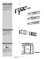 2
2
-
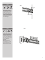 3
3
-
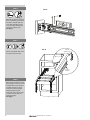 4
4
-
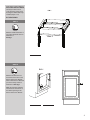 5
5
-
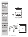 6
6
-
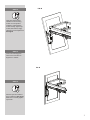 7
7
-
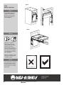 8
8
-
 9
9
-
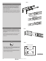 10
10
-
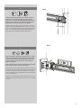 11
11
-
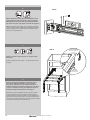 12
12
-
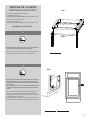 13
13
-
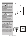 14
14
-
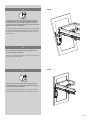 15
15
-
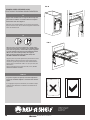 16
16


Rev-A-Shelf 4WCTM-18DM2-175 Mode d'emploi
- Taper
- Mode d'emploi
dans d''autres langues
Documents connexes
-
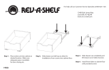 Walker Edison Furniture Company AZ51B29 Mode d'emploi
-
Rev-A-Shelf 4WCTM-1850DM-1 Mode d'emploi
-
-
-
-
-
Rev-A-Shelf 5WB1-1220CR-1 Mode d'emploi
-
-
Rev-A-Shelf 5BBSC-WMDM24-C Mode d'emploi
-
