West Control Solutions RM 201 Mode d'emploi
- Taper
- Mode d'emploi

CANopen Coupler Module RM 201
PMA Prozeß- und Maschinen-Automation GmbH w Postfach 310229 w 34058 Kassel w Deutschland
http://www.pma-online.de w E-Mail: [email protected]
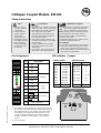
Pin Assignment
Pin Assignment
NC
NC
NC
1CAN H
2CAN GND CAN-Bus
3CAN L
4GND Power
5GND
6+24 V IN supply
7
8Alarm relay
9
Art.-No. 9407-738-20101
DIP ÀBaud rate
0000 10 kBit
0001 20 kBit Á
0010 50 kBit
0011 100 kBit
0100 125 kBit
0101 250 kBit
0110 500 kBit
0111 800 kBit
1000 1000 kBit
1001 Auto Scan
DIP ÀNode-No.
0000 0000 invalid
0000 0001 1
0000 0010 2
0000 0011 3
... ...
0010 0000 32 Á
... ...
0111 1110 126
0111 1111 127
8 Bit DIP switch4 Bit DIP switch
DIP switches / Jumper
Connections
lWiring must be conform to local stan-
dards (e.g. VDE 0100 in Germany) !
lInput leads must be kept separate
from signal and mains leads !
lThe protective earth must be con-
nected to the relevant terminal (in
the instrument carrier) !
lThe cable screening must be con-
nected to the terminal for grounded
measurement !
lUsage of twisted and screened
input leads prevent stray electric
interference !
lConnections must be made accor-
ding to the connecting diagrams !
ESD !
lcontains electro-
statically sensitive
components
lOriginal packing
protects against
electrostatic
discharge (ESD)
lTransporting only in
the original packing
lduring mounting
rules for protection
against ESD must
be followed
Maintenance / Repair
Instrument needs no particular maintenance.
When opening the instrument live
parts or terminals can be exposed.
Before carrying out the instrument must be
disconnected from all voltage sources.
The instrument contains electrostatically
sensitive components.
The following work may be carried out only
by trained, authorized persons.
Fuse tripped:
lCause must be determined and removed !
lOnly fuses of the same type and current
rating as the original fuse must be used.
lUsing repaired fuses or short-circuiting the
fuse socket is inadmissible !
Safety Instructions
Á
ÀThe positions of the switches are shown in binary-code.
The number at the right position corresponds to the LSB
(DIP-switch-position 1), the number at the left position
corresponds to the MSB (DIP-switch-position 4 or 8).
To use the default-mapping of the modular fieldbus-
system in full effect a node number £ 42 should be
chosen.
Factory settings
not active
(default)
termination
active
F1
T 1,6 A
baud rate node-
number
off
on
off
on
LSB LSB
CAN
H
NC
CAN
GND
NC
CAN
L
NC
+24V
IN
Alarm
Receive
Power
Transmit
CAN-CPU
RM 201
1
2
3
8765 4321 Switch-Pos.
4321 Switch-Pos.
4
5
6
7
8
9
Art.-Nr.: 9499-040-58841 w 22.02.01

Technical Data RM 201
Application: central unit of the modular fieldbus system
Power supply: +24 V DC ( ±10 %), max. power consumption 1750 mW (only RM 201)
The GND (^^) of the 24 V DC supply has to be connected to the protective earth(PE).
The module supplies all I/O modules with the required voltages; the max. current
consumption is 1.5 A (depending on the I/O modules used).
Microprocessor: SAB-C505C with 20 MHz
Memory: l32 kByte static RAM
l64 kByte EPROM
l8 kByte EEPROM
CAN-Bus: lFull-CAN-Controller according to CAN-specification V2.0 A
(CAN-specification V2.0 B on request)
lphysical connection according to ISO 11898
lgalvanic isolation via High-Speed-Opto-coupler
lTransmission data rate: 10, 20, 50, 100, 125, 250, 500, 800 and 1000 kBaud
lautomatic baud rate scanning
lRange of node numbers: 0...127 (1...42 in use of default mappings)
lswitchable termination resistor
lProcess-Data-Objects (PDOs):
- Receive £ 5
- Transmit £ 10, max. 5 requestable per 'Remote Transmit Request'
CAN-Protocol: The device operates according to the regulations DS301 and parts of DSP404
passed by the CiA as a CANopen slave.
Protection: The noise immunity of the CAN bus is considerably improved by a
current-compensated choke.
The power supply connection is protected against external interferences such as
voltage peaks by different EMC sources.
Alarm output: The module has an alarm relay output to release for example an emergency stop
in case of defined events. These events can be parameterized via CANopen.
Alarm relay: max. working voltage for a safe protective insulation according to
EN61010-1 with pollution degree 2 and overvoltage category II: 150 V
change-over-contact rating: AC: Pmax = 750 W, 5 A
DC: Pmax = 120 W, 120 V, 5 A
LED displays: l1x ‘Transmit’ (yellow): transmission of a message via CANopen
l1x ‘Receive’ (yellow): receipt of a CANopen message
l1x ‘Power’ (green): state of the supply voltage
l1x ‘Alarm’ (red): state of the alarm relays
Galvanic isolation: The power supply, CAN bus and logic areas are galvanic-isolated from each other
(isolation voltage 500 V DC).
Temperature range: lStorage temperature: -20 ... +70 °C
lAmbient temperature: 0 ... +50 °C
Humidity: £ 75% rel. humidity, no condensation
Shock sensitivity: DIN 40046 IEC68-2-69
EMC: lDIN EN 50081 Part 2
lDIN EN 50082 Part 2
lDIN EN 61326
Electrical connections: screw-/plug-in-terminals, line cross-section max. 2.5 mm²
Class of protection: IP 20
Dimensions: 99 x 17.5 x 114.5 mm (h x w x d)
Weight: 100 g
Housing: Polyamid PA 6.6, combustibility class V0 according to UL 94
Assembly: plugged-in and locked in front of base module
Usage position: vertical
Subject to technical alterations !
-
 1
1
-
 2
2


West Control Solutions RM 201 Mode d'emploi
- Taper
- Mode d'emploi
dans d''autres langues
Autres documents
-
AVENTICS Module de bus BDC, B-Design, CANopen et CANopen sb Le manuel du propriétaire
-
-
WIKA D-20-9 tag:model:D-21-9 Mode d'emploi
-
Eaton DG1-357D6FB-C21C Communications Manual
-
-
ProMinent delta 986524 Supplementary Instructions Manual
-
SICK MLG-2 ProNet FBM Quickstart
-
-
Unitronics V1210-T20BJ Mode d'emploi
-
Baumer MSBA 42 Fiche technique