Fredrick Ramond FR32709 43 Inch 10 Light Linear Suspension Light Manuel utilisateur
- Taper
- Manuel utilisateur

Item No. FR32709 Numéro d’article: FR32079 Número del artículo: FR32709
english spanish french
REVERIE REVERIE REVERIE
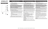
SAFETY WARNING: READ WIRING AND GROUNDING INSTRUC-
TIONS (I.S. 18) AND ANY ADDITIONAL DIRECTIONS. TURN
POWER SUPPLY OFF DURING INSTALLATION. IF NEW WIRING IS
REQUIRED, CONSULT A QUALIFIED ELECTRICIAN OR LOCAL
AUTHORITIES FOR CODE REQUIREMENTS.
Make electrical connections from supply wire to fixture lead wires.
Refer to instruction sheet (I.S. 18) and follow all instructions to make
all necessary wiring connections. Then refer back to this sheet to
complete installation of this fixture.
Shut off electrical current befoer starting. If the fixture you are replacing is
turned on and off by a wall switch, simply turn the switch off. If not,
remove the appropriate fuse (or open the circuit breakers) until the fixture
LVGHDG'2127UHVWRUHFXUUHQWHLWKHUE\IXVHEUHDNHURUVZLWFK
until the new fixture is completely wired and in place.
67(3
Coupez le courant électrique befoer commençant. Si l'appareil que
vous remplacez est allumé et éteint par un interrupteur mural,
éteignez simplement l'interrupteur. Si ce n'est pas le cas, retirer le
fusible approprié (ou ouvrir les disjoncteurs) jusqu'à ce que le
OXPLQDLUHVRLWpWHLQW1(3$6UpWDEOLUOHFRXUDQWVRLWSDUOHIXVLEOH
OHGLVMRQFWHXURXOLQWHUUXSWHXUMXVTXjFHTXHOHQRXYHDXOXminaire
soit complètement câblé et en place.
É7$3(
ADVERTENCIA DE SEGURIDAD: LEA LAS INSTRUCCIONES
DE CABLEADO Y CONEXIÓN A TIERRA (I.S. 18) Y LAS
INSTRUCCIONES ADICIONALES. APAGUE LA ALIMENTACIÓN
ELÉCTRICA DURANTE LA INSTALACIÓN. SI SE REQUIERE UN
NUEVO CABLEADO, CONSULTE A UN ELECTRICISTA CUALI-
FICADO OA LAS AUTORIDADES LOCALES PARA OBTENER
LOS REQUISITOS DEL CÓDIGO.
AVERTISSEMENT DE SÉCURITÉ: LISEZ LES INSTRUCTIONS DE
CÂBLAGE ET DE MISE À LA TERRE (I.S. 18) ET TOUTES AUTRES
DIRECTIONS. ÉTEIGNEZ L'ALIMENTATION ÉLECTRIQUE
PENDANT L'INSTALLATION. SI UN NOUVEAU CÂBLAGE EST
NÉCESSAIRE, CONSULTEZ UN ÉLECTRICIEN QUALIFIÉ OU LES
AUTORITÉS LOCALES POUR OBTENIR DES CODIFICATIONS.
Realice las conexiones eléctricas desde el cable de alimentación
hasta los cables de conexión fijados. Consulte la hoja de instruc
FLRQHV,6\VLJDWRGDVODVLQVWUXFFLRQHVSDUDUHDOL]DUWodas las
conexiones de cableado necesarias. Luego refiérase a esta hoja
para completar la instalación de este artefacto.
(ffectuez les connexions électriques du câble d'alimentation aux fils
GHFRQQH[LRQ5HSRUWH]YRXVjODIHXLOOHGLQVWUXFWLRQV,6HW
suivez toutes les instructions pour effectuer toutes les connexions de
FkEODJHQpFHVVDLUHV5HSRUWH]YRXVHQVXLWHjFHWWHILFKHSRXU
terminer l'installation de cette installation.
Apague la corriente eléctrica antes de comenzar. Si el artefacto que
está reemplazando se enciende y se apaga con un interruptor de
pared, simplemente apague el interruptor'HORFRQWUDULRUHWLUHHO
fusible adecuado (o abra los interruptores automáticos) hasta que el
GLVSRVLWLYRHVWpDSDJDGR12UHVWDXUHODFRUULHQWH\DVHDSRr
fusible, interruptor o interruptor, hasta que el nuevo dispositivo esté
completamente conectado y en su lugar.
3$62
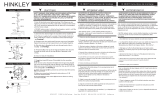
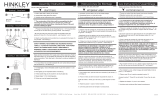
02817,1*,16758&72,1667(0+81* ,16758&&,21(6'(0217$-(%$55$ ,16758&7,216'(0217$*(7,*(
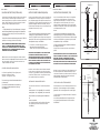
7REHJLQDVVHPEO\RI\RXUIL[WXUHILUVWVOLSVWHPDORQJZLUH
DQGWKUHDGRQWRWKUHDGHGWXEH$DQGWLJKWHQ1RZWKUHDGRWKHU
stem onto top of fixture. making sure loops are parallel to body
VHH'5$:,1*
1H[WUHIHUWRLQVWUXFWLRQVKHHW0RXQWLQJ,QVWUXFWLRQIRU)5
provided, on how tohang your fixture from the ceiling.
2. A continuación, consulte la hoja de instrucciones,
,QVWUXFFLRQHVGHPRQWDMHSDUD)5
incluida, sobre cómo colgar su luminaria del techo.
(QVXLWHUHSRUWH]YRXVjODILFKHG¶LQVWUXFWLRQ,QVWUXFWLRQV
GHPRQWDJHSRXU)5
fournie pour savoir comment accrocher votre luminaire au
plafond.
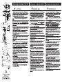
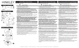
&5<67$/,167$//$7,21$1'/2&$7,21
Your fixture is supplied with 2 sizes of glass panels.
VPDOOVL]H´ORQJDQG´ZLGH
ODUJHVL]H´ORQJDQG´ZLGH
7KHUHDUHWZRULQJZLWKVPDOOKROHVORFDWHGLQVLGHWKH
shade assemlby.
7KHVPDOOVL]HFU\VWDOVDWWDFKHGWRWKHRXWVLGHULQJ
7KHODUJHVL]HFU\VWDOVDWWDFKHGWRWKHLQVLGHULQJ
6HH'5$:,1*
[DRAWING 2]
INSIDE RING
ANILLO INTERIOR
BAGUE INTERIEURE OUTSIDE RING
ANILLO EXTERIOR
BAGUE EXTÉRIEURE
,167$/$&,Ï1 Y8%,&$&,Ï1'(&5,67$/
Su accesorio se suministra con 2 tamaños de paneles de
vidrio.
WDPDxRSHTXHxRORQJLWXG00\DQFKR00
WDPDxRJUDQGHORQJLWXG00\DQFKXUD00
+D\GRVDQLOORVFRQSHTXHxRVDJXMHURVXELFDGRVGHQWUR
del
sombra ensamblada.
Los cristales de pequeño tamaño unidos al anillo exterior.
Los cristales de gran tamaño unidos al anillo interior.
VHU',%8-2
CRIS7AL,167ALLA7,21(7(03/$&(0(17
Votre luminaire est fourni avec 2 tailles de panneaux de verre.
SHWLWHWDLOOHPPGHORQJXHXUHWPPGHODUJHXU
JUDQGHWDLOOHPPGHORQJXHXUHWPPGHODUJHXU
Il y a deux anneaux, avec de petits trous situés à l'intérieur du
assemlby ombre.
Les cristaux de petite taille attachés à la bague extérieure.
Les cristaux de grande taille attachés à l'anneau intérieur.
VRLU'(66,1
SMALL
3(48(f$
3(7,7
/21*
/$5*2
/21*8(
WIRES
WIRES
STEM
FIXTURE
BODY
1
a
1
[DRAWING 1]
3DUDFRPHQ]DUDHQVDPEODUVXSULPHUGLVSRVLWLYRGHVOLFH
HOYiVWDJRDORODUJRGHODODPEUH\ODURVFDDOWXER
roscado (A) y apriételo. Ahora enrosque el otro vástago en la
parte superior del accesorio. asegurándose de que los bucles
HVWpQSDUDOHORVDOFXHUSRYHD',%8-2
3RXUFRPPHQFHUODVVHPEODJHGHYRWUHDSSDUHLOIDLWHV
GDERUGJOLVVHUODWLJHOHORQJGXILOPpWDOOLTXHHWYLVVH]OD
sur le tube fileté (A), puis serrez. Maintenant, enfilez l'autre tige
sur le dessus de l'appareil. en vous assurant que les boucles
VRQWSDUDOOqOHVDXFRUSVYRLU'(66,1

start here commencez ici
empezar aquí
Mounting Instructions FR32709
Instructions de montage FR32709
Instrucciones
De
Montaje FR32709
English Spanish French
J
E
1
2
4
3
10
8
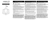
chain
supply wire
ground wire
8
HOOK INSPECTION
CABLE TO MOUNTING STRAP.
Note: Get assistance for this step sinc
SAFETY WARNING: READ WIRING AND GROUNDING INSTRUCTIONS
18) AND ANY ADDITIONAL DIRECTIO
A UALIFIED ELECTRICIAN OR LOCAL AUTHORITIES FOR CODE
u
n
5
.
P
ADVERTENCIA DE SEGURIDAD: LEA LAS INSTRUCCIONES DE
ENCENDIDO Y CONEXIÓN A TIERRA Y -
CIÓN A FUENTE DE TACIÓN
DURANTE LA INST
CONSULTE A UN ELECTRICISTA CALIFICADO O AUTORIDADES
LOCALES ARA T
SÉCURITÉ A T: LIRE LES INSTRUCTIONS DE
A TOUTES LES DIREC-
T TATION
TALLA -
L
AUT
T
e ser t être
6.
6.
9.
5
F
F
10
{DRAWING 1}
{DRAWING 2}

FRIS18
TIERRA CABLEADO INSTRUCCIONES
Advertencia De Seguridad: Lea las Instrucciones de cableado y conexión a tierra
[FRIS 18]
, e
instrucciones adicionales. Encienda la alimentación de corriente durante la instalación. Si se necesita un
nuevo cable, consulte a un electricista calificado o con las autoridades locales de los requisitos del código.
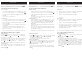
PASO 1 INSTRUCCIONES DE CABLEADO
Accesorios Cubierta
1. Conecte el cable de alimentación positive (A) (normalmente negro o la cara
lisa, sin marcas del ceable de dos conductores) de plomo accesorio positivo
(B) con un giro de tamaño adecuado en el conector – Véase la Figura
1
o
2.
2. Conecte el cable de alimentación negative (C) (por lo general de color blanco
o el lado marcado estriado del cable de dos conductores) de plomo accesorio
negativo (D).
3. Por favor, consulte las Instrucciones de conexión a tierra de abajo para
completer todas las conexiones eléctricas.
Accesorios Exterior
1. Conecte el cable de alimentactión positive (A) (normalmente negro o la cara
lisa, sin marcas del cable de dos conductores) de plomo accesorio positivo
(B) con un giro de tamanño adecuado en el conector - Véase la Figura
1
o
2
.
2. Conectar el cable de alimentación negative (C) (por lo general de color
blanco o el, lado marcado acanalada del cable de dos conductores) a plomo
acesorio negativo (D).
3. Cubra el extreme abierto de conectores con sellador de silicona para formar
un sello hermético.
• Si va a instalar un soporte de fijación mural, use masilla para sellar los
espacios entre la placa de montaje del aparato (placa) y la pared. Esto
ayudará a evitar que el agua entre en la caja de salida. Si la superficie de la
pared es de revestimeinto solapado, utilice masilla y una plataforma de
montaje accesorio espacial.
4. Por favor, consulte las Instrucciones de conexión a tierra a continuación
para completer todas las conexiones eléctricas.
PASO 2 INSTRUCCIONES PUESTA A TIERRA
Flush Mount Fixtures
Para conectar a tierra en un sistema eléctrico de 3 hilos, fije el cable de tierra
del artefacto
(
E
)
(generalmente de cobre o verde recubierto de plástico) a la
brida de montaje fijación
(1)
con el tornillo de tierra
(2)
– Véase la Figura
1
.
Nota: En las correas de accesorios compatibles tornillos, primero instale los
dos tornillos de montaje de la correa.
Cualquier agujero roscado restante puede ser utilizado para el tornillo de tierra.
Chain Hung Fixtures
Loop alambre de tierra
(
E
)
(generalmente de cobre o verde recubierto de
plástico) debajo de la cabeza del tornillo de tierra
(2)
en la brida de montaje
fijación
(1)
y conecte el extremo suelto del cable de tierra luminaria
directamente al cable de tierra del sistema de construcción con un tamaño
adecuado twist conectores – Véase la Figura
2
.
Post-Mount Fixtures
Conecte el cable de tierra del artefacto
(
E
)
(generalmente de cobre o verde
recubierto de plástico) a tierra de la fuente de alimentactión con conector de
tamaño adecuado en el interior puesto enlaces en forma. Cubra el extremo
abierto del conector con sellador de silicona para formar un sello hermético -
Véase la Figura
3
.
FRIS18
CÂBLAGE ÉCHOUAGE INSTRUCTIONS
Avertissement De Sécurité: Lire câblage et de mise à la terre instructions
[FRIS 18]
et les
instructions supplémentaires. Couper l’alimentation électrique pendant l’installation. Si un nouveau câblage nést
nécessaire, consultez un ékectricien qualifié ou les autorités locales pour connaître les exigences du code.
ETAPE 1 INSTRUCTIONS DE CÂBLAGE
Luminaires Itérieurs
1. Branchez le câble d’alimentation positive (A) (généralement noir ou, côté
lisse banalisée de la corde à deux conducteurs) au plomb de fixation positive
(B) avec la torsion de taille appropriée sur le connecteur - Voir Schéma
1
et
2
2. Raccorder le fil d’alimentation negative (C) (généralement blanc ou l’, côté
marqué nervurée du fil à deux conducteurs) au conducteur négatif de
l’appareil (D).
3. S’il vous plait se referrer aux instructions ci-dessous pour remplir la terre
toutes les connexions électriques.
Luminaires Extérieurs
1. Brancher le fil d’alimentation positive (A) (généralement noir ou, côté lisse
banalisée de la corde à deux conducteur) à plomb de fixation positive (B) avec
la torsion de taille appropriée sur le connecteur – Voir Schéma
1
ou
2
.
2. Connecter le fil d’alimentation negative (C) (généralement blanc ou l’, côté
marqué nervurée du fil à deux conducteurs) au conducteur négatif de
l’appareil (D).
3. Couvrir extrémité ouberte de connecteurs avec du silicone pour former un
joint étanche à l’eau.
• Se l’installation d’un luminaire de montage mural, utiliser calfeautrage pour
sceller l’espace entre la plaque de montage de fixation (plaque arrière) et la
paroi. Cela aidera à emp6echer l’eau de pénétrer dans la boîte de sortie. Si la
surface du mur est bardage à clin, utiliser calfeautrage et une plate-forme de
montage d’appareils spécialement.
4. S’il vous plait se referrer aux instructions ci-dessous pour terminer la terre
toutes les connexions électriques.
ETAPE 2 INSTRUCTIONS DE MISE
Montage Encastré Fixtures
Pour la terre positive dans un système électrique à 3 fils, fixez le fil de terre du
luminaire
(E)
(généralement en cuivre ou vert recouvert de plastique) à la sangle
de fixation de fixation
(1)
avec la vis de terre
(2)
– Voir Schéma
1
.
Remarque: Sur les sangles pour les appareils pris en charge à vis, installez
d’abord les deux vis de fixation à sangle.
Tout trou taraudé restante peut être utilisée pour la vis de terre.
Chaîne Accroché Luminaires
Boucle fil du luminaire au sol (E) (généralement en cuivre ou vert recouvert de
plastique) sous la tête de la vis de terre
(2)
sur la sangle de fixation de fixation
(1)
et se connecter à l’extrémité libre du fil de terre du luminaire directement
sur le fil de terre du système de construction avec une taille appropriée
connecteurs à visser - Voir Schéma
2
.
Luminaires Aprés Montage
Brancher le fil de terre du luminaire (E) (généralement en cuivre ou vert
recouvert de plastique) à la masse de l’alimentation avec une taille appropriée
torsion sur le conecteur à l’intérieur de la poste. Couvrir extrémité ouverte du
connecteur avec du mastic silicone pour former un joint ètache à l’eau – Voir
Schéma
3
.
FRIS18
WIRING AND GROUNDING INSTRUCTIONS
Safety Warning: Read wiring and grounding instructions
[FRIS 18]
and any additional
directions. Turn power supply off during installation. If new wiring is required, consult a qualified electrician
or local authorities for code requirements.
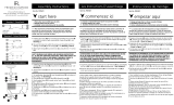
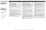
STEP 1 WIRING INSTRUCTIONS
Indoor Fixtures
1. Connect positive supply wire (A) (typically black or the smooth, unmarked
side of the two-conductor cord) to positive fixture lead (B) with
appropriately sized twist on connector – See Drawing 1 or 2.
2. Connect negative supply wire (C) (typically white or the ribbed, marked side
of the two-conductor cord) to negative fixture lead (D)
3. Please refer to the grounding instructions below to complete all electrical
connections.
Outdoor Fixtures
1. Connect positive supply wire (A) (typically black or the smooth, unmarked
side of the two-conductor cord) to positive fixture lead (B) with
appropriately sized twist on connector – See Drawing 1 or 2.
2. Connect negative supply wire (C) (typically white or the ribbed, marked side
of the two-conductor cord) to negative fixture lead (D)
3. Cover open end of connectors with silicone sealant to form a watertight seal.
• If installing a wall mount fixture, use caulk to seal gaps between the fixture
mounting plate (backplate) and the wall. This will help prevent water from
entering the outlet box. If the wall surface is lap siding, use caulk and a
fixture mounting platform specially.
4. Please refer to the grounding instructions below to complete all electrical
connections.
STEP 2 GROUNDING INSTRUCTIONS
Montaje Embutido Accesorios
For positive grounding in a 3-wire electrical system, fasten the fixture ground
wire
(
E
)
(typically copper or green plastic coated) to the fixture mounting strap
(1)
with the ground screw
(2)
– See Drawing
1
.
Note: On straps for screw supported fixtures, first install the two mounting
screws in strap.
Any remaining tapped hole may be used for the ground screw.
Cadena Hung Accesorios
Loop fixture ground wire
(
E
)
(typically copper or green plastic coated) under
the head of the ground screw
(2)
on fixture mounting strap
(1)
and connect to
the loose end of the fixture ground wire directly to the ground wire of the
building system with appropriately sized twist-on connectors – See Drawing
2
.
Accesorios Posterior Monte
Connect fixture ground wire
(E)
(typically copper or green plastic coated) to
power supply ground with appropriately sized twist-on connector inside post.
Cover open end of connector with silicone sealant to form a watertight seal –
See Drawing
3
.
[DRAWING 1]
[DRAWING 2]
[DRAWING 3]
A Division of Hinkley Lighting Inc.
33000 PIN OAK PARKWAY | AVON LAKE, OHIO 44012
toll free 800.446.5539 | phone 440.653.5500
08.23.13
-
 1
1
-
 2
2
-
 3
3


Fredrick Ramond FR32709 43 Inch 10 Light Linear Suspension Light Manuel utilisateur
- Taper
- Manuel utilisateur
dans d''autres langues
Autres documents
-
 Hinkley FR35601BRG Manuel utilisateur
-
LARK 83257 Manuel utilisateur
-
Hinkley FR30908 Manuel utilisateur
-
 Hinkley 12071BU Manuel utilisateur
-
 Hinkley 29307 Rhodes 1 Light Outdoor Hanging Lantern Manuel utilisateur
-
 Hinkley Lighting 51803PN Guide d'installation
-
 Hinkley Lighting 2931DZ-LL Guide d'installation
-
 Hinkley Lighting 5353PN Guide d'installation
-
 Hinkley 3023DG Guide d'installation
-
Hinkley Lighting 2800DZ Mode d'emploi


