Dometic Aircommand Ibis 3 Guide d'installation
- Taper
- Guide d'installation

Ibis 3 Owners Guide Revision V6 Page 1 of 19
IBIS 3 OWNERS MANUAL
Contents
WARRANTY OF REFRIGERATED AIRCONDITIONING ________________________________________________ 2
GENERAL UNIT INFORMATION __________________________________________________________________ 4
PACKING LIST ________________________________________________________________________________ 5
BEFORE INSTALLATION YOU MUST COMPLETE THE FOLLOWING STEPS _____________________________ 6
INSTALLATION ________________________________________________________________________________ 7
COMMISSIONING OF THE UNIT _________________________________________________________________ 11
MAINTENANCE _______________________________________________________________________________ 12
GENERAL SPECIFICATIONS ___________________________________________________________________ 13
OPERATING INSTRUCTIONS ___________________________________________________________________ 14
IBIS 3 WIRING DIAGRAM _______________________________________________________________________ 18
TROUBLE SHOOTING GUIDE ___________________________________________________________________ 19

Ibis 3 Owners Guide Revision V6 Page 2 of 19
WARRANTY OF REFRIGERATED AIRCONDITIONING
Warranty within Australia
We undertake by this warranty to rectify, free of charge, at our nearest authorised service agent, any fault due to faulty workmanship or replacement of any faulty
components within 12 months from the date of the first retail purchase thereof. This undertaking is conditional upon the appliance being installed and operated in
accordance with our instructions, and does not apply to consumable components such as filters, or to adjustments necessary due to misuse of airconditioner. Normal
user maintenance, setting of controls and transit damage are also excluded. No other person, firm or corporation is authorised by us to offer or give on our behalf any
other or greater warranty than that given by us under this warranty. The benefits conferred by this warranty are in favour of the original retail purchaser and any other
person deriving title to the goods through or under such person and are intended to be separate from the additional to all other rights and remedies which they may have
in law in respect of the goods. Warranty is void if used on commercial applications, including trucks, prime movers, locomotives & machinery.
1. In the event that warranty service is required, the purchaser must contact Aircommand Australia for service approval.
Contact information: phone +61 8 8345 8444, fax 08 8243 0628, or email sales@aircommand.com.au
2. Warranty repairs will only to be carried out by the manufacturer’s authorised service repairer.
3. It is the purchaser’s responsibility to deliver unit to the manufacturers nearest authorised Service Centre.
The manufacturer will not bear any costs involved in Service Agent’s travelling expenses or delivery charges.
Warranty outside Australia
1. Aircommand products are covered by 12 months warranty from date of first retail purchase.
2. For warranty enquiries outside Australia, please contact your national supplier.
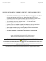
* The warranty card must be completed and returned to the manufacturer for registration, or to the distributor in country of purchase. Online
warranty registration is available at www.aircommand.com.au/registration.html
GARANTIE FÜR KLIMAGERÄT MIT KÜHLFUNKTION
Garantie innerhalb Australiens
Wir verpflichten uns mit dieser Garantie, innerhalb von 12 Monaten ab Datum des ersten Einzelhandelskaufs, über unseren nächsten Vertragshändler jeden
durch fehlerhafte Verarbeitung entstandenen Defekt kostenlos zu beheben oder alle defekten Teile kostenlos auszutauschen. Diese Verpflichtung gilt unter
dem Vorbehalt, dass das Gerät im Einklang mit unseren Anleitungen installiert und betrieben wird, und gilt nicht für Verschleißteile wie z.B. Filter oder für
Korrekturarbeiten, die durch den Missbrauch des Klimageräts bedingt sind. Normale Wartung durch den Benutzer, die Einstellung der Bedienelemente und
Transportschäden sind ebenfalls ausgeschlossen. Wir haben keine anderen Personen, Firmen oder Unternehmen bevollmächtigt, in unserem Namen irgendeine
andere oder weiter reichende Garantie anzubieten oder zu geben als die von uns im Rahmen dieser Garantie erteilte. Die mittels dieser Garantie gewährten
Leistungen gelten zu Gunsten des ursprünglichen Einzelhandelskäufers oder jeder anderen Person, die ihren Anspruch auf die Waren durch oder von dieser Person
ableitet, und sind dazu gedacht, getrennt von allen zusätzlichen Rechten und Behelfen zu gelten, die ihnen kraft Gesetzes hinsichtlich dieser Waren zustehen.
1. Für den Fall, dass eine Garantieleistung erforderlich wird, muss sich der Käufer mit Aircommand Australia zur Genehmigung der
Leistung in Verbindung setzen. Kontaktinfo: Tel. +61 8 8345 8444, Fax: 08 8243 0628 oder E-Mail: sales@aircommand.com.au
2. Unter die Garantie fallende Reparaturen werden nur durch den Vertragsreparaturdienst des Herstellers ausgeführt.
3. Die Lieferung des Geräts an das nächstliegende Service Centre des Herstellers ist Aufgabe des Käufers.
Der Hersteller deckt keine der durch die Anfahrtskosten des Vertragsdienstes oder Lieferkosten entstandenen Ausgaben.
Garantie außerhalb Australiens
1. Für die Produkte von Aircommand gilt eine 12-monatige Garantie ab Datum des ersten Einzelhandelskaufs.
2. Für Garantieanfragen außerhalb Australiens wenden Sie sich bitte an Ihren inländischen Händler.
* Die Garantiekarte ist auszufüllen und dem Hersteller, bzw. dem Vertriebshändler im Einkaufsland, zur Registrierung zuzuschicken. Die Garantie kann online unter der
folgenden Adresse registriert werden: www.aircommand.com.au/registration.html
GARANTIE DE CLIMATISATION RÉFRIGÉRÉE
Garantie pour l’Australie
Nous nous engageons par cette garantie à faire rectifier gratuitement par notre agent de service tout défaut résultant d’un défaut de fabrication ou de remplacer tout
composant défectueux dans les 12 mois suivant la date du premier achat de l’appareil au détail. Cet engagement est conditionnel à l’installation et à l’exploitation
de l’appareil conformément à nos instructions, et ne s’applique pas aux composants consommables tels que les filtres, ou à un réglage attribuable à la mauvaise
utilisation du climatiseur. L’entretien, les réglages des commandes et les dommages en transit sont également exclus. Aucune autre personne, firme ou entreprise n’est
autorisée par nous à offrir ou à donner en notre nom toute autre garantie ou une garantie supérieure à celle donnée par nous en vertu de cette garantie. Les avantages
conférés par cette garantie reviennent à l’acquéreur au détail original ou à toute autre personne qui deviendra propriétaire de l’appareil par le biais de cette personne
ou avec son autorisation et sont censés être supplémentaires à tous les autres droits et recours dont il pourra disposer légalement en ce qui concerne l’appareil.
1. Au cas où un service de garantie serait nécessaire, l’acquéreur doit contacter Aircommand Australia pour obtenir une autorisation de service.
Cordonnées: téléphone +61 8 8345 8444, fax 08 8243 0628, ou email sales@aircommand.com.au
2. Les réparations sous garantie seront effectuées exclusivement par le réparateur autorisé du fabricant.
3. La responsabilité incombe à l’acquéreur de livrer l’appareil au Centre de service autorisé le plus proche du fabricant.
Le fabricant ne subira pas les frais de déplacement ou de livraison de l’agent de service.
Garantie en dehors de l’Australie
1. Les produits Aircommand sont couverts par une garantie de 12 mois à compter de la date du premier achat au détail.
2. Pour toute demande de renseignements en dehors de l’Australie, veuillez contacter votre fournisseur national.
* La carte de garantie doit être remplie et renvoyée au fabricant pour être enregistrée, ou au distributeur dans le pays de l’achat. Un enregistrement de garantie en ligne
est
disponible sur www.aircommand.com.au/registration.html
GARANTÍA DEL ACONDICIONADOR DE AIRE REFRIGERADO
Garantía en Australia
Nos comprometemos por medio de esta garantía a rectificar, sin cargo, en nuestra agencia de servicio autorizado, cualquier fallo causado por un componente
defectuoso dentro de los 12 meses contados a partir de la primera fecha de compra. Este compromiso es condicional a que el aparato haya sido instalado y
operado de acuerdo con nuestras instrucciones y no cubre componentes de consumo tales como filtros, o cualquier ajuste necesario debido al uso incorrecto del
acondicionador de aire. Se excluyen también las tareas de mantenimiento normales, el ajuste de los controles y cualquier daño ocurrido durante su transporte.
Ninguna otra persona, firma o corporación está autorizada a ofrecer o dar en nuestro nombre una garantía más extensa o diferente a la otorgada por esta garantía. Los
beneficios conferidos por esta garantía son a favor del comprador original y cualquier otra persona que tenga derecho al título de la mercadería a través o bajo dicha
persona y está separada de otros derechos adicionales o soluciones a las que puedan tener derecho, según la ley, respecto a las mercaderías.
1. En el caso que se necesite hacer uso del servicio de garantía, el comprador debe ponerse en contacto con Aircommand Australia para la aprobación del
servicio. Información de contacto: Teléfono: +61 8 8345 8444, fax 08 8243 0628 o Email sal[email protected].au
2. Las reparaciones cubiertas por la garantía deberán ser llevadas a cabo por el servicio de reparaciones autorizado por el fabricante.
3.. La entrega de la unidad al Centro de Servicio más cercano autorizado por el fabricante es responsabilidad del comprador
El fabricante no se hará responsable de ninguno de los costes involucrados por gastos de viaje o cargos de entrega por parte del agente
proveedor del
servicio
Garantía fuera de Australia
1. Los productos de Aircommand están cubiertos por 12 meses de garantía a partir de la primera fecha de compra.
2. Por cualquier información respecto a la garantía fuera de Australia, sírvase ponerse en contacto con su proveedor nacional.
* Esta tarjeta de garantía debe ser completada y enviada al fabricante para su debida registración o alternativamente al distribuidor en el país de compra. La
registración de la garantía puede hacerse también online en: www.aircommand.com.au/registration.html

Ibis 3 Owners Guide Revision V6 Page 3 of 19
HEAD OFFICE
Aircommand
Australia Pty Ltd
954-956 Port Road
Albert Park, SA 5014
ACN 164 415 445
For warranty claims, sales
enquires or customer
service
Call:
(08) 8345 8444
Fax:
(08) 8243 0628
Email:
service@aircommand.com.au
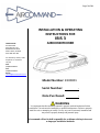
INSTALLATION & OPERATING
INSTRUCTIONS FOR
IBIS 3
AIRCONDITIONER
Model Number: 8100001
Serial Number: .
Date Purchased: .
WARNING
It is important that this installation manual is properly read and understood before
installation. The unit must be installed by a qualified tradesperson. Failure to properly
install the unit or attempting to modify it in any way can be extremely hazardous and
may result in property damage and personal injury.
Aircommand will not be held responsible for problems relating to incorrect
or improper installation methods.

Ibis 3 Owners Guide Revision V6 Page 4 of 19
GENERAL UNIT INFORMATION
I. PURPOSE
The Aircommand Ibis 3 air conditioning unit was designed for installation on the roof of a caravan or recreational vehicle to
provide reverse cycle heating and cooling. The unit is intended for vehicles with roofs that are from 25 to 85mm thick. The unit
must be installed so that it is within ±5° of the horizontal plane. It is important that the unit is installed properly according to the
recommended guidelines.
II. ENSURING EFFECTIVE OPERATION
The effectiveness of the air conditioner is dependent on several factors that contribute to the total heat load on the van. When
an Aircommand unit is installed in a van or motorhome Aircommand assumes that the vehicle manufacturer or owner has
properly assessed the potential heat load or sought expert advice and selected the appropriate capacity air conditioning unit.
Roof hatches will significantly increase the heat load into the caravan. Where possible avoid installing roof hatches or only install
hatches that can be effectively insulated. The increase in heat load far outweighs the gain from natural lighting.
The following actions can be taken to reduce peak heat load and help the air-conditioner deliver the most comfort:
Closing all doors, hatches, windows and blinds. Extend all annexes.
Position the vehicle so that the annex will face the sun and protect the windows from direct solar radiation.
Turning off unneeded appliances that might increase the heat load inside the van.
Cook outside if possible.
Park the caravan/RV in a shaded position.
In periods of extreme high temperature it is recommended to start the air conditioner earlier in the morning to greatly
improve its ability to cope with the expected peak heat load.
III. CONDENSATION
In areas of high humidity, the humid air within the van will cause “sweating” or condensation in parts of the unit as the humid,
warm air contacts the colder air discharged from the system. If this occurs please ensure the following:
Close all doors, hatches, windows and blinds to limit the ingress of warm humid air.
Avoid running the inside fan on LOW or AUTO in humid conditions. Running the fan on HIGH fan speed will result in higher
airflow and reduce the tendency to have condensation form.
Aircommand will not be held responsible for damage caused by condensation.
IV. GENERATORS
The Ibis 3 is designed to run using mains power, however many owners may want to use portable generators to run the unit
when in remote locations. Any generator used should deliver high quality, pure sine wave, alternating current at 50Hz, and be
able to handle the compressor start up demand. Given the vast range in quantity and quality of generators on the market
Aircommand cannot recommend a specific model or brand. Discuss your specific requirements with the generator supplier
directly and consider their recommendations.
Aircommand will not be held responsible for damages due to the use of improper generators and such use may void your
warranty.

Ibis 3 Owners Guide Revision V6 Page 5 of 19
PACKING LIST
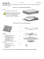
The components of your Ibis 3 will be contained in 2 cartons. Unpack the carton when you are ready to install and check that
the contents are as below:
Main Carton - 1160 x 890 x 250mm Weight 47kg
Contents:
1. Ibis 3 Roof top air conditioner – 1 only
IMPORTANT – Pay attention to the orientation
of the ‘This Way UP ‘ arrows on the carton.
If the unit has been upside-down for any
period of time then DO NOT install.
Contact Aircommand Australia for advice
Plenum Carton- 557 x 577 x 119mm Weight 3kg
Contents:
1. Weather seal collar – 1 only
2. Duct & Brace – 1 only
3. M8 x 120mm bolts, washers &
hold down bars – 4 sets
4. Plenum assembly - 1 only
5. Return air filter - 1 only
6. Remote control & bracket – 1 only
Not shown
Wood screws, counter sunk
#8 x ½” – 8 only
Metal threads, Pan head, white
M4 x 25 -- 4 only
This booklet
If you note that any items are missing or damaged then please contact Aircommand Australia

Ibis 3 Owners Guide Revision V6 Page 6 of 19
BEFORE INSTALLATION YOU MUST COMPLETE THE FOLLOWING STEPS
Checked that roof thickness is between 25 – 85mm. If roof is greater than 85mm
thick you will need an Ibis 3 Thick roof adapter (Part No 8102007) from
Aircommand. Note that this measurement must include any ‘H-Frames’ used.
Confirmed that the unit will be within ±5° of the horizontal plane.
The installation instruction sections (pages 7 - 10) have been read.
Roof strength has been assessed.
Position of the unit has been assessed for clearance on the roof and ceiling.
The installation hole will not cut through any wiring in the roof.
Mains power or battery driven inverter power supply has been isolated.
Selected the correct sealant for your application.
Safe work method for lifting unit onto the roof top has been assessed.
Installation must conform to local wiring regulations.
DO NOT attempt to modify or add components to the installation procedure.
This equipment must only be serviced by a licensed refrigeration mechanic.
If your installation varies from the method outlined please contact Aircommand for specialty advice.
WARNING
The unit weighs approximately 46kg, ensure a two person lift or use a mechanical hoist to avoid the risk of
injury.
Failure to properly install the unit or attempting to modify it in any way can be extremely hazardous and may result in
property damage and/or personal injury.
Aircommand will not be held responsible for issues arising from incorrect or improper installation methods.

Ibis 3 Owners Guide Revision V6 Page 7 of 19
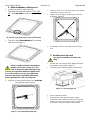
INSTALLATION
Mark out the position of the
unit based on the following
important requirements:
Before cutting holes through the roof
ensure that mains power or battery driven
inverters are disconnected
The unit requires a 360 x 360mm square hole for
installation.
The Ibis 3 should be placed as close as possible to
the centre of the caravan or RV so that conditioned
air can circulate evenly.
Ensure that the air outlets will not be blowing
directly onto obstructions.
Consideration should be given to service access.
Ensure that location of hatches, solar panels,
antennas etc will not prevent access for service
personnel.
The roof MUST be strong enough to support the
weight of the unit (46kg). Contact your caravan
manufacturer to confirm that this load can be
supported by the roof.
EXTERNAL CLEARANCE. The path of the
outside fan exhaust must be free. A gap of at least
50mm is required between the roof top unit and
any obstructions.Figure 1
Figure 1 - Foot print of the roof top air conditioner over
360 x 360mm mounting hole. The area at the back
(shown in cross hatch) must be kept free of
obstructions.
INTERNAL CLEARANCE The inside plenum has
a foot print of 535 x 535 mm centered around the
installation hole. Figure 2
Figure 2- Inside plenum foot print.
The installation hole must be boxed up with
material that is strong enough to withstand the
compression from the hold down bolts. 20mm wide
timber would be required at a minimum.
Contact Aircommand if your installation differs
significantly from that prescribed above.
1. Cut installation hole
WARNING
There may be electrical wiring located in
the ceiling space. Ensure that power is properly
disconnected at the supply (mains and/or battery).
Failure to do so may result in personal injury or
death.
Once the position of the unit has been determined
cut out the 360 x 360 installation hole and boxed
up.
Ensure that the main power supply for the unit has
been led through and is available for connection.
The installation hole must be sealed from the
ceiling space to prevent air conditioned air leaking
into the ceiling cavity.

Ibis 3 Owners Guide Revision V6 Page 8 of 19
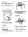
2. Attach weather collar to roof
Locate the weather collar (Item #1).
The collar has one side marked “THIS SIDE
UP”. This top side will point to the sky. Figure
3
Figure 3 - Top side of weather collar showing THIS SIDE
UP also has 4 grey foam strips around each bolt hole
The other side, the underside will be sealed
onto the roof. Figure 4
Figure 4 - The underside of the weather collar
Select a suitable sealant for bonding the
weather collar to the caravan roof. The
collar is made from glass filled Nylon-6,6.
Consult your specialist adhesive supplier about
the correct sealant to use for your application.
Follow all directions on the MSDS particularly
those regarding PPE, safe use & disposal.
Apply the recommended sealant to the underside
of the weather collar Figure 5
Figure 5 - Recommended sealant path
Flip the collar over and firmly press the sealant
side to the roof of the caravan.
Apply a circle of sealant around each of the four
bolt holes. Figure 6
Figure 6 - Sealant around bolt holes on the top side
The weather collar is now ready for the roof top
unit.
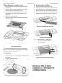
3. Position roof top unit
Use approved methods to lift the unit –
46kg.
Position the unit over the 360 x 360mm hole with
the weather collar installed.Figure 7
Lower the unit so that it engages with the collar.
Figure 7– Lower & engage unit
Move inside the caravan.
Note position of the electrical power supply
entering the 360 x 360 hole. If the roof is thin (25-
30mm) you may have to put a notch in the duct &
brace part in order to lead the cable through.

Ibis 3 Owners Guide Revision V6 Page 9 of 19
4. Electrical supply
This unit MUST be installed in accordance
with AS/NZ 3001:2008 “Electrical
installations – transportable structures & vehicles
including their site supplies’. Ensure that power is
properly disconnected at the supply (mains and/or
battery). Failure to do so may result in personal
injury or death. This connection can only be done
by a suitably licensed electrical tradesperson.
From inside the caravan look up and locate the
unit’s connection point. Figure 8
Undo the 2 screws securing the connection box.
Pull the box out to allow for easier access. Prepare
cable, connect conductors to appropriate
terminals. Tighten cable gland. Replace
connection box and secure with both screws.
Figure 8 - Hard wire connection point
5. Secure unit to roof
Assemble the M8 bolts, washers and hold down
bars. (Item #3)
Raise the Duct and brace (Item #2) towards the
installed unit.
Insert the M8 Bolt assembly through the corner
holes. Figure 9
Engage the bolts into the unit.
Ensure that the hold down bars are aligned with
their recess.
Tighten the 4 bolts evenly.
Tighten the bolts to 12 – 14 Nm torque.
Do not exceed 14 Nm.
If required #8 x ¾” pan head screws can be used
to further secure the edges of the Duct and brace
(Item #2) to the ceiling. Insert screws through the 2
holes on two of the sides.
Figure 9- Assemble Bolt, washer & bar into duct & brace
6. Connect return air duct
Reach up between the diagonal arms of the duct &
brace. Grasp the white plastic collar on the end of
the concertina duct.
Pull the collar downwards until it engages with the
central duct. Figure 10
Pull until the collar snaps into place with the 4
catches on the diagonal arms.
Figure 10 - Engage central duct
7. Attach plenum assembly
Locate the Plenum assembly (Item #4) and
remove the filter (Item #5). See Figure 16
Locate 4 of the M4 x 25 metal threads
Connect the control cable that leads from the
plenum to the roof top unit. Ensure the plug mates
with the socket and catch is engaged. Figure 11
Figure 11 - Connect control cable
From plenum
From roof top unit

Ibis 3 Owners Guide Revision V6 Page 10 of 19
Attach plenum assembly cont.
Raise the plenum assembly towards the roof top
installation.
Engage a M4 x 25 metal thread into one of the 4
holes in the corner of the filter recess.
Raise the plenum and engage the screw into its
mating hole on the diagonal arm of the brace.
Figure 12
Repeat for 3 other threads.
Tighten screws until the plenum has been pulled
up to the ceiling.
Figure 12 - Connect plenum cover to brace arms with 4
M4 x 20 metal threads
In some installations the ceiling may be uneven
and one or more sides of the plenum will require
additional fixtures. Figure 13
IF REQUIRED …..
Screw in #8 x ½” countersunk wood screws
provided.
Tighten until gap is gone.
Install cover caps.
Figure 13 - Extra screws to close gap around plenum
8. Install return air filter
Locate the return air filter. (Item #5).
Align the tabs on one side of the filter body
with matching slots in the plenum. Insert the
filter into the recess in the plenum. Figure 14
Push the filter upwards until both catches
engage and hold the filter in place. Figure 15
Figure 14 - Insert filter tabs into slots
Figure 15 - Push upwards
1. To remove the filter Figure 16:
1. Push both tabs inwards
2. Swing down
Figure 16 - Remove filter from plenum
INSTALLATION IS NOW
COMPLETE – PROCEED TO
COMMISSIONING
1
2

Ibis 3 Owners Guide Revision V6 Page 11 of 19
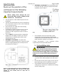
COMMISSIONING OF THE UNIT
Turn the power on at the circuit breaker.
Using the remote control (Item #6) press the
ON/OFF button. Figure 17. Each command from
the remote control should be answered by a ‘beep’
from the receiver in the plenum.
Figure 17 - Turn unit on
Press the MODE button until FAN mode is
selected. Figure 18
Figure 18 - Select FAN mode
Press the FAN button to cycle through High –
Medium – Low fan speeds. Figure 19. Note air
flow as the speeds change.
Figure 19 - Change fan speed
Press MODE button until COOL is selected.
Figure 20
Figure 20 - Select COOL mode
Decrease the set point temperature below the
room temperature by pressing the
TEMPERATURE DOWN button. Figure 21. The
compressor will start within three minutes. Run unit
until you can feel cool air from plenum outlets.
Figure 21 - Decrease SET POINT temperature
Note: Regardless of the mode selected there will
always be a delay before the compressor starts. This
delay is to protect the compressor and cannot be over
ridden.
Set mode to HEAT, and increase the set point
temperature above the room temperature. Figure
22. After the protection delay the compressor will
start.
Figure 22 - Change to HEAT mode and increase SET
POINT

Ibis 3 Owners Guide Revision V6 Page 12 of 19
Note: In heating mode the fan will not begin blowing
air until the inside coil has reached a temperature of at
least 30⁰C. This is to prevent cold draughts. Fan speed
will increase to the set speed as the coil temperature
increases.
Press ON/OFF button once more to turn the unit
off.
Commission check list
Unit beeps when remote buttons are pressed
Fan runs and air volume changes with speed
Cooling mode produces cool air
Heating mode produces warm air
ON / OFF button turns the unit on & off
COMMISSION IS NOW COMPLETE
MAINTENANCE
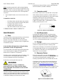
1. Filter
The filter must be cleaned periodically to ensure that it
does not become clogged with dust and other
particles. The state of the filter can be ascertained
from its appearance, if it appears dirty or clogged then
it should be cleaned.
A blocked filter will impair the cooling & heating
performance of the unit significantly.
To clean the filter, first remove it by pushing both tabs
on the side to release. Figure 16. Swing the filter
down and out. Figure 15 & Figure 14.
The filter can be washed with warm soapy water. Care
must be taken to avoid ripping the fabric. The filter
must be completely dry before reinstallation.
Replace by reversing the above process.
WARNING
Airborne particles can pose a health risk,
particularly to young children and the elderly.
Ensure that filters are cleaned in a safe and well
ventilated area
The filter should be cleaned every four weeks or more
when in use. Prolonged use, higher concentrations of
airborne particles and various other factors may result
in the filters needing to be cleaned more often.
Replacement return air filters can be ordered directly
from Aircommand. (Part No. 8102044)
2. Remote control
The remote control can be cleaned with a damp cloth.
If the remote will not be used for a period of time it is
recommended that the batteries are removed & stored
separately. Remove the cover to the battery
compartment by sliding in direction shown below
Figure 23. Replace with 2 x AAA batteries. Check
battery polarity. Replace cover.
Figure 23 - Remote control batteries
3. Hold Down bolts
Aircommand suggests that the 4 hold down bolts
attaching the unit to the roof are initially checked for
tightness within the first 3 months of installation, and
thereafter every 12 months if the van is in constant
use. The recommended bolt torque is 12-14 Nm.
4. Storage
The air conditioner should be run on a routine basis to
ensure the components remain in working order.
If the van is in storage or is to remain unoccupied for
an extended length of time it is recommended that the
air conditioner is allowed to run uninterrupted for 20-
30min once every six months.
5. Warranty Claims
The unit comes with a one year manufacturer’s
warranty from date of purchase. It is IMPORTANT that
you read and understand the conditions of the
warranty agreement which are included with the unit.
If you have a claim contact Aircommand directly on
(08) 8345 8444, alternatively you can fax (08) 8243
0628 or email service@aircommand.com.au, please
have your unit serial number ready, which can be
found in the installation folder or refer to Figure 24 for
the location of the serial number on the outside unit.
Figure 24 - Serial number location

Ibis 3 Owners Guide Revision V6 Page 13 of 19
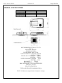
GENERAL SPECIFICATIONS
Model 8100001
Roof top Unit
Inside Plenum
Height (mm)
222
32
Width (mm)
848
535
Length (mm)
1120
535
Weight (kg)
45
1
AIRCOMMAND AUSTRALIA PTY LTD
IBIS 3
MODEL NO. 8100001
230-240V AC 50Hz
REFRIGERANT 407C 870g
RATED CAPACITY COOLING 3100 W
HEATING 2700 W
POWER INPUT COOLING 1300 W
HEATING 1210 W
RATED CURRENT COOLING 5.8 A
HEATING 5.5 A
MAX INPUT 1700 W
MAX CURRENT 7.5 A
MAX. DISCHARGE / SUCTION PRESSURE
3000 kPa / 700 kPa
PROOF RATING IP24
TOTAL AIR DELIVERY MAXIMUM 180 l/s
E&OE All values are approximate & subject to change

Ibis 3 Owners Guide Revision V6 Page 14 of 19
OPERATING INSTRUCTIONS
WARNING
This appliance is not intended for use by persons (including children) with reduced physical, sensory or
mental capabilities, or lack of experience and knowledge, unless they have been given supervision or
instruction concerning use of the appliance by a person responsible for their safety.
Remote Control Operation
The remote control is used to control all functions of the air conditioner. See Figure 25.
Figure 25
Fan speed Display
High / Medium / Low / Auto
Clock & Timer Display
Real time clock
Timer ON / Timer OFF
Temperature set point
Display
16 °C – 30 °C
Mode Display
COOL / DRY / HEAT/ AUTO /
FAN
Sleep Function Display
1 - On / Off
Turns unit from standby
to ON and vice versa.
11 & 12 – Temperature up /
down
Increase or decrease the desired
temperature set point for your
comfort.
Also acts to increase / decrease
time during timer & clock
setting
10 - Fan Speed
Select from High, Medium and
Low In cooling and heating mode
AUTO FAN speed can be
selected.
2 - Mode
COOL – decrease air
temperature
DRY – Dehumidify the air
HEAT – increase room
temperature
AUTO – automatically selects
heat or cooling mode as required
FAN – Circulates air
3 - Sleep
Allows the controller to gradually
depart from the set point
temperature while you sleep.
Improves your comfort.
4 & 5 – Timer on & Timer off
Use these buttons to set the time
for unit to turn on and off
automatically.
6 - Clock
Used to set
local time on
the remote.
7 - Set
Used to finish
clock & timer
settings
8 - Light
Turn on display
back light for 5
seconds
9 - Send
Transmit the remote
control’s settings to the air
conditioner

Ibis 3 Owners Guide Revision V6 Page 15 of 19
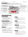
Plenum Status Display (Figure 26)
In addition to the remote control there is a status display on the corner of the inside plenum.
This row of lights indicates the mode that the air conditioner is operating in.
The MANUAL OPERATION BUTTON can be used to access basic functions without the remote.
Figure 26 - Status display in corner of inside plenum
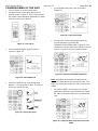
OPERATION USING REMOTE CONTROL
SET CLOCK ON REMOTE
Press CLOCK (Figure 25– Button #6) Clock
icon will flash on display.
Use Temperature UP / DOWN (Figure 25–
Button #11 & 12) to change time.
When time is correctly displayed press SET
(Figure 25 – Button #7)
SET TIMER ON AND TIMER OFF – Note you
must complete SET CLOCK first
Press TIMER ON (Figure 25 – Button #4)
Temperature UP / DOWN to change time
When time is correctly displayed press SET
(Figure 25– Button #7)
Repeat above process with TIMER OFF
(Figure 25– Button #5)
To cancel either timers press the TIMER ON or
TIMER OFF button twice
COOLING MODE
Turn unit ON (Figure 25– Button #1) (Figure
17)
Press MODE (Figure 25– Button #2) until
COOL is displayed in the Mode Display
(Figure 20)
Press FAN SPEED (Figure 25 – Button #10)
until the required speed is selected (Figure
19)
Press TEMPERATURE UP / DOWN for your
required set point temperature. (Figure 21)
DRY MODE
Turn unit ON
Press MODE until DRY is displayed in the
Mode Display
Press TEMPERATURE UP / DOWN for your
required set point temperature.
FAN MODE
Turn unit ON
Press MODE until FAN is displayed in the
Mode Display
Press FAN SPEED until the required speed is
selected
HEATING MODE
Turn unit ON
Press MODE until HEAT is displayed in the
Mode Display
We recommend AUTO fan speed is selected
in heating mode
Press TEMPERATURE UP / DOWN for your
required set point temperature.
AUTO MODE
Turn unit ON
Press MODE until AUTO is displayed in the
Mode Display
Press FAN SPEED until the required speed is
selected
Press TEMPERATURE UP / DOWN for your
required set point temperature.
Mode indicator lights
A coloured LED illuminates above
mode that the unit is operating in.
Example shown – Cool
Fault Indication
Operation faults are indicated
by a number of rapid flashes of
the FAN LED
Refer to trouble shooting guide
& contact Aircommand for
service advice.
Manual operation button
On occasion when the remote
has been lost or is not working it
is possible to access basic
functions with this button.
Press to cycle through
ON / COOL / FAN / HEAT / OFF

Ibis 3 Owners Guide Revision V6 Page 16 of 19
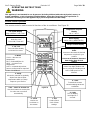
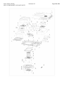
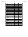
IBIS 3 COMPONENTS & SPARE PARTS

Ibis 3 Owners Guide Revision V6 Page 17 of 19
#
Part Description
Part #
QTY
Order spare part #
1
Screw M5x12 - White
8101001
13
8101011
2
Canopy - Ibis 3
8101020
1
8101020
3
Speed clip - M5
8101002
13
8101011
4
Base - Ibis 3
8101030
1
NA
5
Evaporator housing
8101005
1
8101005
6
Evaporator fan deck
8101006
1
NA
7
Compressor, horizontal 240V AC R407C
0018260
1
NA
8
Fan mounting plate
8101007
2
NA
9
Lead through clip - LHS
8101003
2
NA
10
Lead through clip - RHS
8101004
2
NA
11
Inside fan stud
8101008
4
NA
12
Accumulator holder
8101009
1
NA
13A
Fan, centrifugal 310, Inside
8101010
1
8101010
13B
Fan, centrifugal 310, Outside
8101011
1
8101011
14
Outside coil, 3 row
8101011
1
NA
15
Hermetic piping assembly
8101012
1
NA
16
Inside coil, 2 row
8101013
1
NA
17
End plate, inside coil
8101014
1
NA
18
Hold down plate, piping
8101015
1
NA
19
Electrical box - RHS
8101016
3
NA
20
Electrical box lid - RHS
8101017
1
NA
21
Electrical box - LHS
8101018
1
NA
22
Electrical box lid - LHS
8101019
1
NA
23
Control card V4.0 & sensors
5601069
1
5601069
24
Capacitor - Compressor run 30uF / 450V
4101072
1
4101072
25
Capacitor - Compressor start 64-77uF / 330V
8101021
1
8101021
26
PTC
8001042
1
8001042
27
Brace & Grille
8102008
1
8102008
28
Spiral duct collar
8102009
1
8102012
29
Spiral duct
8102010
1
8102012
30
Weather collar
5861001
1
5861001
31
Weather collar seal
5861003
1
5861003
32
Bolt M8 x 120
4001034
4
8002037
33
Ceiling bar
1802063
4
8002037
34
Low profile plenum cover
8102006
1
8102007
35
Cap, screw hole
0018164
8
0018164
36
Air louver
8102011
4
8102007
37
Return air filter
8102044
1
8102044
38
IR Receiver board
5601072
1
8102007
39
IR Receiver bezel
8102011
1
8102007
40
IR receiver window
8102012
1
8102007
41
Receiver push button
8102013
1
8102007
42
Remote control with holder
5601071
1
5601071

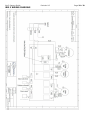
Ibis 3 Owners Guide Revision V6 Page 18 of 19
IBIS 3 WIRING DIAGRAM

Ibis 3 Owners Guide Revision V6 Page 19 of 19
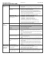
TROUBLE SHOOTING GUIDE
Symptom
Cause
Correction
Unit does not
operate
No power supply to unit
Check that mains power is plugged into van and that the supply is
switched ON.
Check the van’s air-conditioner power circuit breaker is ‘ON’
Remote control is not
operating
Check the remote control screen. If blank then replace batteries
See Figure 23 - Remote control batteries.
Stand close to unit and point remote directly towards the IR
receiver in the plenum. Test operation of remote. If there is no
‘beep’ from the air conditioner then replace batteries and re test.
See Figure 23 - Remote control batteries.
Test air conditioner operation by using manual operation button.
See Figure 26 - Status display in corner of inside plenum.
Fault condition rapid
flashes of ‘Fan’ indicator
light on plenum
4 rapid flashes – inside coil not cooling “E4”
5 rapid flashes – return air sensor fault “E1”
6 rapid flashes – inside coil sensor fault “E2”
7 rapid flashes – outside coil sensor fault “E3”
8 rapid flashes - outside coil over temperature “E5”
Continuous flashing without break - communication fault
Contact Aircommand Australia for specialist advice on fault
correction and access to our service agents.
Poor cooling or
heating
performance
Return air filter is blocked
Remove filter, clean & replace. See Figure 16 - Remove filter from
plenum. Clean filter every 4 weeks, more frequently with high use
Air outlets are closed
Ensure that at least 2 outlets are opened. Highest capacity occurs
when all 4 outlets are fully opened.
Outside fan air intake is
blocked
Check that debris has not blocked the external air intake of the roof
top unit. Clear intake grille.
High outside air
temperatures in cooling
Take action to reduce your peak heat load – extend awnings, close
blinds, windows & hatches, start air conditioner earlier in the
morning.
Discuss your expected heat load with your caravan supplier and size
the air conditioning capacity to suit.
Outside air temperature exceeds the unit’s operating temperature
range.
Low outside air
temperatures in heating
Discuss expected heat loss with your caravan supplier and size air
conditioning capacity to suit.
Outside air temperature is below the unit’s operating temperature
range.
Intermittent operation
during very hot & very cold
days
During cooling on very hot days the compressor overload may be
activated. This is to protect the unit. Take all steps to reduce heat
load on caravan.
During heating on cold mornings the unit will periodically enter
automatic de-ice mode to clear ice from its outside coil. Heat mode
light will flash. Normal operation will resume once ice has been
melted.
Water coming from
roof top unit and
draining across the
outside of the
caravan roof
In cooling mode this is
‘condensate’ water that has
been removed from the air
inside your van
This is normal. The unit will dehumidify air inside the caravan and
provide more comfortable living conditions.
In humid conditions close doors, windows and hatches.
Run the inside fan on High or Medium.
Avoid using Low or Auto fan speeds in these conditions
In heating mode this is
water that has been melted
during de-ice cycles
This is normal. During heating on cold mornings the unit will
periodically enter automatic de-ice mode to clear ice from the
outside coil. Normal operation will resume once ice has been
melted.
-
 1
1
-
 2
2
-
 3
3
-
 4
4
-
 5
5
-
 6
6
-
 7
7
-
 8
8
-
 9
9
-
 10
10
-
 11
11
-
 12
12
-
 13
13
-
 14
14
-
 15
15
-
 16
16
-
 17
17
-
 18
18
-
 19
19