
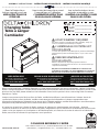
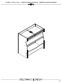
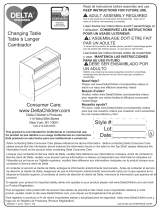
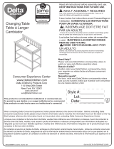
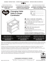
Changing Table
Table à Langer
Cambiador
March 30, 2020, 26373, R5
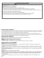
Read all instructions
before assembly and use.
KEEP INSTRUCTIONS FOR
FUTURE USE.
Lisez toutes les instructions avant
l’assemblage et l’utilisation.
CONSERVEZ LES INSTRUCTIONS
POUR UN USAGE ULTERIEUR.
Lea todas las instrucciones
antes de ensamblar y usar.
MANTENGA LAS INSTRUCCIONES
PARA SU USO FUTURO.
When contacting Delta Consumer Experience Center please reference the above information. Before contacting
Delta Consumer Experience Center please ensure that the information above matches the information found on the
label on the Top Shelf, please reference the information found on the product when contacting Delta Consumer
Experience Center.
Lorsque vous contactez le Service client de Delta, veuillez faire référence aux informations ci-dessus. Avant de
contacter le Service client de Delta, veuillez vous assurer que les informations ci-dessus correspondent aux
informations indiquées sur l’étiquette qui se trouve sur le Tablette supérieur; veuillez faire référence aux informations
indiquées sur le produit lorsque vous contactez le Service client de Delta.
Al contactar al servicio al cliente de Delta, entregue la información anteriormente mencionada. Antes de
contactar al servicio de atención al cliente de Delta, asegúrese de que la información anteriormente mencionada
calza con la que aparece en la etiqueta en el Estante superior; al contactar al centro de atención al cliente de
Delta, mencione la información que aparece en el producto.
CONSUMER EXPERIENCE CENTER
Delta Children’s Products Corp |114 West 26th Street New York, NY 10001
(646) 435-8727 | [email protected] | www.DeltaChildren.com
Style #:
Lot:
Date:
___________
___________
___________
A
REV
This product is not intended for institutional or commercial use.
Ce produit ne pas destine a un usage institutionnel ou commercial.
Este producto no esta hecho para uso institucional o comercial.
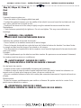
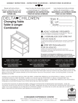
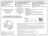
ADULT ASSEMBLY REQUIRED
Due to the presence of small parts during assembly, keep out
of reach of children until assembly is complete.
L’ASSEMBLAGE DOIT ETRE FAIT
PAR UN ADULTE
A cause de la presence de petites pieces, pendant l’assemblage
gardez hors de portee des enfants jusqu'a ce que celui-ci soit
termine.
DEBE SER ENSAMBLADO
POR UN ADULTO
Debido a la presencia de piezas pequeñas durante el
ensamblaje, mantenga fuera del alcance de los niños hasta que
complete el ensamblaje.
NEED EXTRA HELP?
We make assembly easy with
our tips & tricks video
https://www.deltachildren.com/
pages/instructions
BESOIN D'AIDE SUPPLÉMENTAIRE?
Nous facilitons l'assemblage avec
nos trucs et astuces vidéo
https://www.deltachildren.com/
pages/instructions
¿NECESITA AYUDA EXTRA?
Hacemos el montaje fácil con
nuestros consejos y trucos video
https://www.deltachildren.com/
pages/instructions
©2020 DELTA ENTERPRISE CORP.
ASSEMBLY INSTRUCTIONS • INSTRUCTIONS DE MONTAGE • INSTRUCCIONES DE MONTAJE
La page est en cours de chargement...

DELTA CHILDREN
@deltachildren
SUIVEZ NOUS POUR AVOIR PLUS DE CHANCES DE GAGNER /
SÍGANOS PARA TENER MAS CHANCES DE GANAR
SCANNEZ ICI / ESCANEE AQUÍ
Pour plus d'informations et
pour voir tous nos produits
Para más información y para
ver todos nuestros productos
ÉCONOMISEZ BEAUCOUP AVEC
AHORRE MUCHO CON
Visitez Deltachilren.com Pour Commencer Vos Achats
Visita Deltachilren.com Para Comenzar A Comprar
FAMILLE DELTA
Bienvenue dans la
Voici Notre Cadeau Pour Vous
Votre Prochain Achat Chez
*Subject to Change
*Exclusions Apply
*Des exclusions s’appliquent
*Sujet à changement
Aquí Está Nuestro Regalo Para Usted
FAMILIA DELTA
Bienvenido a la
Su Próxima Compra En
DeltaChildren.com
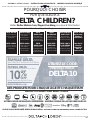
DELTA10
UTILISEZ LE CODE:
UTILICE EL CÓDIGO:
ECRIVEZ UN COMMENTAIRE CLIENT pour ce produit sur le site web du magasin où il a été acheté
CALIFIQUE EL PRODUCTO en la página web de la tienda donde haya sido comprado
1
FAITES UNE CAPTURE D’ECRAN de votre commentaire client et mettez la en ligne sur www.DeltaChildren.com/Review
HAGA UNA CAPTURA DE PANTALLA de su calificación y cárguela a la pagina www.DeltaChildren.com/Review
2
C’EST AUSSI SIMPLE QUE ÇA! Dès que c’est fait vous serez instantanément INSCRIT POUR GAGNER 2500$
ES ASÍ DE FÁCIL! En cuanto lo envíe ya estará instantáneamente PARTICIPANDO PARA GANAR $2.500
3
REGLEMENT DE PARTICIPATION / REGLAS PARA PARTICIPAR
LAISSEZ UN COMMENTAIRE CLIENT POUR GAGNER $2500
CALIFIQUE EL PRODUCTO PARA GANAR $2500
3
ASSEMBLY INSTRUCTIONS • INSTRUCTIONS DE MONTAGE • INSTRUCCIONES DE MONTAJE

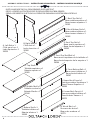
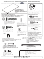
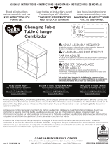
PARTS: MAKE SURE THAT ALL PRE-ASSEMBLED PARTS ARE TIGHT
PIÈCES : VÉRIFIEZ QUE TOUTES LES PIÈCES PRÉ-MONTÉES SONT BIEN SERRÉES.
PIEZAS: ASEGÚRESE DE QUE TODAS LAS PIEZAS PRE-ENSAMBLADAS ESTÁN BIEN APRETADAS.
4
A. Left Side x 1
Côté gauche x 1
Lado izquierdo x 1
26359
G. Top Shelf x 1
Tablette supérieur x 1
Estante superior x 1
26365
H. Middle Shelf x 1
Tablette central x 1
Estante Medio x 1
26366
J. Bottom Shelf x 1
Tablette inférieur x 1
Estante inferior x 1
26368
B. Right Side x 1
Côté droit x 1
Lado derecho x 1
26360
C. Back Top Rail x 1
Barre arrière supérieur x 1
Barra trasero superior x 1
26361
D. Back Bottom Rail x 1
Barre arrière inférieur x 1
Barra trasero inferior x 1
26362
E. Front Top Rail x 1
Barre avant supérieur x 1
Barra frontal superior x 1
26363
F. Front Top Shelf Rail x 1
Barre avant supérieur de la tablette x 1
Barra frontal superior de la esquina x 1
26364
K. Front Bottom Rail x 1
Barre avant inférieur x 1
Barra frontal inferior x 1
26367
L. Upper Back Panel x 1
Panneau arrière Supérieur x 1
Panel Trasero Superior x 1
26369
M. Lower Back Panel x 1
Panneau arrière Inférieur x 1
Panel Inferior Trasero x 1
26370
N. Wood Block x 1
Morceau de bois x 1
Bloque de madera x 1
26371
ASSEMBLY INSTRUCTIONS • INSTRUCTIONS DE MONTAGE • INSTRUCCIONES DE MONTAJE

5
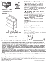
V. M6 x 7 mm Nut x 2
Écrou M6x7mm x 2
Tuerca M6x7mm x 2
4065
U. Nylon Washer x 4
Rondelle de nylon x 4
Arandela de Nylon x 4
5525
W. Changer Strap x 1
Sangle du Table à Langer x 1
Correa de Cambiador x 1
21748
Y. Metal Bracket x 1
Support métallique x 1
soporte de metal x 1
5956
Parts: Hardware kits part#26372
Pièces: L'ensemble de quincaillerie - pièce n°26372
Piezas: El kit de herramientas - Pieza #26372
Y. M6 x 45 mm Bolt x 14
Boulon M6 x 45 mm x 14
Perno M6 x 45mm x 14
5466
R. M6 x 25 mm Bolt x 5
Boulon M6 x 25 mm x 5
Perno M6 x 25mm x 5
5462
S. M6x13mm Barrel Nut x 14
Écrous À Portée Cylindrique M6x13 mm x 14
Tuerca Cilíndrica M6x13mm x 14
5483
T. Φ8x25 mm Wood Dowel x 20
Cheville en bois Φ8x25mm x 20
Pasador de madera Φ8x25mm x 20
5741
M4 Allen Wrench (included)
Clé Allen M4 (inclus)
Llave Allen M4 (incluido)
1177
X. 15 mm Screw x 18
Vis de 15 mm x 18
Tornillo de 15 mm x 18
5577
Flat Head Screwdriver (not supplied)
Tournevis à tête plate (non fourni)
Destornillador plano (no suministrado)
Phillips Screwdriver (Not Provided)
Tournevis’Phillips’(Non Prévu)
Destornillardor’Phillips’(No siempre)
No drills necessary. Do not use power
screwdriver.
Aucun forage n’est nécessaire. Ne pas
utiliser de tournevis électrique.
No hace falta taladrar No utilice
destornilladores eléctricos
P. Changer Pad x 1
Matelas à Langer x 1
Superficie para Cambios x 1
21282
A pliers or adjustable wrench is
required for assembly.
Des pinces ou une clé anglaise sont
nécessaires pour le montage.
Se necesita unos alicates o una llave
ajustable para ensamblar.
ASSEMBLY INSTRUCTIONS • INSTRUCTIONS DE MONTAGE • INSTRUCCIONES DE MONTAJE

6
Step 1 / Étape 1 / Paso 1
Parts and tools required to complete step
Pièces et outils nécessaires au montage
Piezas y herramientas necesarias para completar este paso
Y. M6 x 45 mm Bolt x 2
Boulon M6 x 45 mm x 2
Perno M6 x 45mm x 2
S. M6x13mm Barrel Nut x 2
Écrous À Portée Cylindrique M6x13 mm x 2
Tuerca Cilíndrica M6x13mm x 2
T. Φ8x25 mm Wood Dowel x 2
Cheville en bois Φ8x25mm x 2
Pasador de madera Φ8x25mm x 2
M4 Allen Wrench (included)
Clé Allen M4 (inclus)
Llave Allen M4 (incluido)
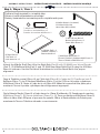
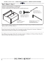
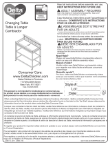
Attach the Middle Shelf (Part H) to the Right Side (Part B) with (2) Φ8x25 mm Wood Dowels
(Part T), (2) M6x45mm Bolts (Part Y) and (2) M6x13mm Barrel Nuts (Part S) using the M4 Allen
Wrench as shown. Use the Flat Head Screwdriver to hold the Barrel Nut in the proper
alignment.
Fixez le Tablette central (Pièce H) au Côté droit (Pièce B) à l’aide de (2) Cheville en bois Φ
8x25mm (Pièce T), de (2) Boulons M6x45mm (Pièce Y) et de (2) Écrou à portée cylindrique
M6x13mm (Pièce S). Serrer à l’aide de la clé Allen M4. Utiliser le tournevis à tête plate pour
maintenir l’écrou à portée cylindrique dans l'alignement approprié.
Fije la Estante Medio (Pieza H) al Lado derecho (Pieza B) utilizando (2) Pasadores de madera
Φ8x25mm (Pieza T), (2) Pernos M6x45mm (Pieza Y) y (2) Tuercas cilíndricas M6x13mm (Pieza S).
Utilice la Llave Allen M4 para el proceso de apriete. Utilice el Destornillador de Paleta para
mantener la Tuerca Cilíndrica alineado correctamente.
B. Right Side x 1
Côté droit x 1
Lado derecho x 1
H. Middle Shelf x 1
Tablette central x 1
Estante Medio x 1
ASSEMBLY INSTRUCTIONS • INSTRUCTIONS DE MONTAGE • INSTRUCCIONES DE MONTAJE
La page est en cours de chargement...

8
Step 2 / Étape 2 / Paso 2
Parts and tools required to complete step
Pièces et outils nécessaires au montage
Piezas y herramientas necesarias para completar este paso
T. Φ8x25 mm Wood Dowel x 3
Cheville en bois Φ8x25mm x 3
Pasador de madera Φ8x25mm x 3
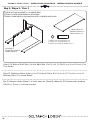
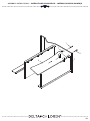
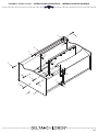
Attach (1) Back Top Rail (Part C) and (1) Back Bottom Rail (Part D) to the Right Side (Part B)
with (3) Φ8x25 mm Wood Dowels (Part T) as shown.
Fixez (1) Barre arrière supérieur (pièce C)
et de (1) Barre arrière inférieur (pièce D) au Côté droit
(Pièce B) à l’aide de (3) Cheville en bois Φ8x25mm (Pièce T) comme illustré.
Fije (1) Barra trasero superior (Pieza C) y (1) Barra trasero inferior (Pieza D)
al Lado derecho
(Pieza B) utilizando (3) Pasadores de madera Φ8x25mm (Pieza T) como se muestra.
From Step 1
À partir de l’étape 1
Desde el paso 1
D. Back Bottom Rail x 1
Barre arrière inférieur x 1
Barra trasero inferior x 1
C. Back Top Rail x 1
Barre arrière supérieur x 1
Barra trasero superior x 1
ASSEMBLY INSTRUCTIONS • INSTRUCTIONS DE MONTAGE • INSTRUCCIONES DE MONTAJE
La page est en cours de chargement...

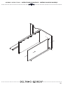
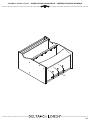
J. Bottom Shelf x 1
Tablette inférieur x 1
Estante inferior x 1
Attach (1) Bottom Shelf (Part J) to the Right Side (Part B) with (2) Φ8x25 mm Wood Dowels (Part
T) as shown.
Fixez (1) Tablette inférieur (pièce J) au Côté droit (Pièce B) à l’aide de (2) Cheville en bois Φ
8x25mm (Pièce T) comme illustré.
Fije (1) Estante inferior (Pieza J)
al Lado derecho (Pieza B) utilizando (2) Pasadores de madera
Φ8x25mm (Pieza T) como se muestra.
10
Step 3 / Étape 3 / Paso 3
Parts and tools required to complete step
Pièces et outils nécessaires au montage
Piezas y herramientas necesarias para completar este paso
T. Φ8x25 mm Wood Dowel x 2
Cheville en bois Φ8x25mm x 2
Pasador de madera Φ8x25mm x 2
From Step 2
À partir de l’étape 2
Desde el paso 2
ASSEMBLY INSTRUCTIONS • INSTRUCTIONS DE MONTAGE • INSTRUCCIONES DE MONTAJE
La page est en cours de chargement...

12
Step 4 / Étape 4 / Paso 4
Parts and tools required to complete step
Pièces et outils nécessaires au montage
Piezas y herramientas necesarias para completar este paso
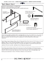
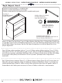
K. Front Bottom Rail x 1
Barre avant inférieur x 1
Barra frontal inferior x 1
Y. M6 x 45 mm Bolt x 2
Boulon M6 x 45 mm x 2
Perno M6 x 45mm x 2
S. M6x13mm Barrel Nut x 2
Écrous À Portée Cylindrique M6x13 mm x 2
Tuerca Cilíndrica M6x13mm x 2
T. Φ8x25 mm Wood Dowel x 2
Cheville en bois Φ8x25mm x 2
Pasador de madera Φ8x25mm x 2
M4 Allen Wrench (included)
Clé Allen M4 (inclus)
Llave Allen M4 (incluido)
Attach the Front Bottom Rail (Part K) to the Right Side (Part B) with (2) Φ8x25 mm Wood Dowels
(Part T), (2) M6x45mm Bolts (Part Y) and (2) M6x13mm Barrel Nuts (Part S) using the M4 Allen
Wrench as shown. Use the Flat Head Screwdriver to hold the Barrel Nut in the proper
alignment.
Fixez le Barre avant inférieur (Pièce K) au Côté droit (Pièce B) à l’aide de (2) Cheville en bois Φ
8x25mm (Pièce T), de (2) Boulons M6x45mm (Pièce Y) et de (2) Écrou à portée cylindrique
M6x13mm (Pièce S). Serrer à l’aide de la clé Allen M4. Utiliser le tournevis à tête plate pour
maintenir l’écrou à portée cylindrique dans l'alignement approprié.
Fije la Barra frontal inferior (Pieza K) al Lado derecho (Pieza B) utilizando (2) Pasadores de
madera Φ8x25mm (Pieza T), (2) Pernos M6x45mm (Pieza Y) y (2) Tuercas cilíndricas M6x13mm
(Pieza S). Utilice la Llave Allen M4 para el proceso de apriete. Utilice el Destornillador de
Paleta para mantener la Tuerca Cilíndrica alineado correctamente.
From Step 3
À partir de l’étape 3
Desde el paso 3
ASSEMBLY INSTRUCTIONS • INSTRUCTIONS DE MONTAGE • INSTRUCCIONES DE MONTAJE
La page est en cours de chargement...

14
Step 5 / Étape 5 / Paso 5
Parts and tools required to complete step
Pièces et outils nécessaires au montage
Piezas y herramientas necesarias para completar este paso
G. Top Shelf x 1
Tablette supérieur x 1
Estante superior x 1
From Step 4
À partir de l’étape 4
Desde el paso 4
F. Front Top Shelf Rail x 1
Barre avant supérieur de la tablette x 1
Barra frontal superior de la esquina x 1
Attach (1) Top Shelf (Part G) and (1) Front Top Shelf Rail (Part F) to the Right Side (Part B) as
shown.
Fixez (1) Tablette supérieur (pièce G)
et de (1) Barre avant supérieur de la tablette (pièce F) au
Côté droit (Pièce B) à l’aide de (3) Cheville en bois Φ8x25mm (Pièce T) comme illustré.
Fije (1) Estante superior (Pieza G) y (1) Barra frontal superior de la esquina (Pieza F)
al Lado
derecho (Pieza B) utilizando (3) Pasadores de madera Φ8x25mm (Pieza T) como se muestra.
ASSEMBLY INSTRUCTIONS • INSTRUCTIONS DE MONTAGE • INSTRUCCIONES DE MONTAJE
La page est en cours de chargement...

16
Step 6 / Étape 6 / Paso 6
Parts and tools required to complete step
Pièces et outils nécessaires au montage
Piezas y herramientas necesarias para completar este paso
T. Φ8x25 mm Wood Dowel x 11
Cheville en bois Φ8x25mm x 11
Pasador de madera Φ8x25mm x 11
From Step 5
À partir de l’étape 5
Desde el paso 5
Y. M6 x 45 mm Bolt x 6
Boulon M6 x 45 mm x 6
Perno M6 x 45mm x 6
S. M6x13mm Barrel Nut x 6
Écrous À Portée Cylindrique M6x13 mm x 6
Tuerca Cilíndrica M6x13mm x 6
M4 Allen Wrench (included)
Clé Allen M4 (inclus)
Llave Allen M4 (incluido)
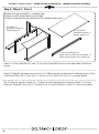
Attach (1) Left Side (Part A) and (1) Front Top Rail (Part E) to the assembly from step 5 with (11)
Φ8x25 mm Wood Dowels (Part T), (6) M6x45 mm Bolts (Part Y) and (6) M6x13mm Barrel Nuts
(Part S) using the M4 Allen Wrench as shown. Use the Flat Head Screwdriver to hold the Barrel
Nut in the proper alignment.
Fixez (1) Côté gauche (Pièce A)
et de (1) Barre avant supérieur (pièce E) à l’ensemble monté à
l’étape 5 à l’aide de (11) Chevilles en bois Φ8x25mm (Pièce T), de (6) Boulons 45mm (Pièce Y)
et de (6) Écrou à portée cylindrique M6x13mm (Pièce S). Serrer à l’aide de la clé Allen M4.
Utiliser le tournevis à tête plate pour maintenir l’écrou à portée cylindrique dans l'alignement
approprié.
Fije (1) Lado izquierdo (Pieza A) y (1) Barra frontal superior (Pieza E) a la pieza del paso 5
utilizando (11) Pasadores de madera Φ8x25mm (Pieza T), (6) Pernos 65mm (Pieza Y) y (6)
Tuercas cilíndricas M6x13mm (Pieza S). Utilice la Llave Allen M4 para el proceso de apriete.
Utilice el Destornillador de Paleta para mantener la Tuerca Cilíndrica alineado correctamente.
A. Left Side x 1
Côté gauche x 1
Lado izquierdo x 1
E. Front Top Rail x 1
Barre avant supérieur x 1
Barra frontal superior x 1
ASSEMBLY INSTRUCTIONS • INSTRUCTIONS DE MONTAGE • INSTRUCCIONES DE MONTAJE
La page est en cours de chargement...

18
Step 7 / Étape 7 / Paso 7
Parts and tools required to complete step
Pièces et outils nécessaires au montage
Piezas y herramientas necesarias para completar este paso
From Step 6
À partir de l’étape 6
Desde el paso 6
M4 Allen Wrench (included)
Clé Allen M4 (inclus)
Llave Allen M4 (incluido)
R. M6 x 25 mm Bolt x 3
Boulon M6 x 25 mm x 3
Perno M6 x 25mm x 3
N. Wood Block x 1
Morceau de bois x 1
Bloque de madera x 1
Attach the Wood Block (Part N) to the assembly from step 6 using (3) M6x25 mm Bolts (Part R).
Tighten with the M4 Allen Wrench.
Fixez le morceau de bois (Pièce N) à l’ensemble monté à l’étape 6 à l’aide de (3) Boulons
25mm (Pièce R). Serrer à l’aide de la clé hexagonale M4.
Fije el Bloque de madera (Pieza N) a la pieza del paso 6 utilizando (3) Pernos 25mm (Pieza R).
Utilice la Llave Allen M4 para el proceso de apriete.
ASSEMBLY INSTRUCTIONS • INSTRUCTIONS DE MONTAGE • INSTRUCCIONES DE MONTAJE
La page est en cours de chargement...

20
Step 8 / Étape 8 / Paso 8
Parts and tools required to complete step
Pièces et outils nécessaires au montage
Piezas y herramientas necesarias para completar este paso
Y. M6 x 45 mm Bolt x 4
Boulon M6 x 45 mm x 4
Perno M6 x 45mm x 4
S. M6x13mm Barrel Nut x 4
Écrous À Portée Cylindrique M6x13 mm x 4
Tuerca Cilíndrica M6x13mm x 4
M4 Allen Wrench (included)
Clé Allen M4 (inclus)
Llave Allen M4 (incluido)
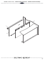
Attach (1) Back Top Rail (Part C) and (1) Back Bottom Rail (Part D) to (1) Right Side (Part B) and
(1) Left Side (Part A) with (4) M6x45mm Bolts (Part Y) and (4) M6x13mm Barrel Nuts (Part S) using
the M4 Allen Wrench as shown. Use the Flat Head Screwdriver to hold the Barrel Nut in the
proper alignment.
Fixez (1) Barre arrière supérieur (pièce C)
et de (1) Barre arrière inférieur (pièce D) au (1) Côté
droit (Pièce B)
et de (1) Côté gauche (pièce A) à l’aide de (4) Boulons M6x45mm (Pièce Y) et
de (4) Écrou à portée cylindrique M6x13mm (Pièce S). Serrer à l’aide de la clé Allen M4. Utiliser
le tournevis à tête plate pour maintenir l’écrou à portée cylindrique dans l'alignement
approprié.
Fije (1) Barra trasero superior (Pieza C) y (1) Barra trasero inferior (Pieza D) al (1) Lado derecho
(Pieza B) y (1) Lado izquierdo (Pieza A) utilizando (4) Pernos M6x45mm (Pieza Y) y (4) Tuercas
cilíndricas M6x13mm (Pieza S). Utilice la Llave Allen M4 para el proceso de apriete. Utilice el
Destornillador de Paleta para mantener la Tuerca Cilíndrica alineado correctamente.
From Step 7
À partir de l’étape 7
Desde el paso 7
ASSEMBLY INSTRUCTIONS • INSTRUCTIONS DE MONTAGE • INSTRUCCIONES DE MONTAJE
La page est en cours de chargement...

22
Step 9 / Étape 9 / Paso 9
Parts and tools required to complete step
Pièces et outils nécessaires au montage
Piezas y herramientas necesarias para completar este paso
From Step 8
À partir de l’étape 8
Desde el paso 8
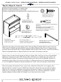
Attach (1) Metal Bracket (Part Y) to (1) Back Top Rail (Part C) and (1) Front Top Shelf Rail (Part
F) using (2) 15 mm Screws (Part X). Tighten with the Phillips Screwdriver.
Fixez le Support métallique (Pièce Y) à le Barre arrière supérieur (Pièce C) et à le Barre avant
supérieur de la tablette (Pièce F) à l’aide de (2) vis 15mm (Pièce X). Serrer à l’aide de la
Tournevis’Phillips’.
Fije le soprote de metal a la Barra trasero superior (Pieza C) y a la Barre avant supérieur de la
tablette (Pieza F) utilizando (2) tornillos 15mm (Pieza X). Apriete utilizando un destornillador
Phillips.
Phillips Screwdriver (Not Provided)
Tournevis’Phillips’(Non Prévu)
Destornillardor’Phillips’(No siempre)
X. 15 mm Screw x 2
Vis de 15 mm x 2
Tornillo de 15 mm x 2
Y. Metal Bracket x 1
Support métallique x 1
soporte de metal x 1
ASSEMBLY INSTRUCTIONS • INSTRUCTIONS DE MONTAGE • INSTRUCCIONES DE MONTAJE

23
Y
Y
X
F
Both ends
Deux extrémités
Ambos extremos
ASSEMBLY INSTRUCTIONS • INSTRUCTIONS DE MONTAGE • INSTRUCCIONES DE MONTAJE

24
Step 10 / Étape 10 / Paso 10
Parts and tools required to complete step
Pièces et outils nécessaires au montage
Piezas y herramientas necesarias para completar este paso
X. 15 mm Screw x 16
Vis de 15 mm x 16
Tornillo de 15 mm x 16
From Step 9
À partir de l’étape 9
Desde el paso 9
Phillips Screwdriver (Not Provided)
Tournevis’Phillips’(Non Prévu)
Destornillardor’Phillips’(No siempre)
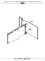
L. Upper Back Panel x 1
Panneau arrière Supérieur x 1
Panel Trasero Superior x 1
M. Lower Back Panel x 1
Panneau arrière Inférieur x 1
Panel Inferior Trasero x 1
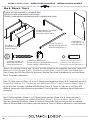
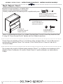
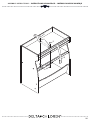
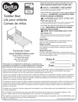
Attach (1) Upper Back Panel (Part L) and (1) Lower Back Panel (Part M) to the assembly from
step 9 using (16) 15 mm Screws (Part X). Tighten with the Phillips Screwdriver. Ensure the
Address Label is facing to the back of the unit.
Fixez (1) Panneau arrière Supérieur (Pièce L) et (1) Panneau arrière Inférieur (Pièce M) à
l’ensemble monté à l’étape 9 à l’aide de (16) vis 15mm (Pièce X). Serrez à l'aide d’un
tournevis Phillips. Assurez-vous que l’étiquette d’adresse est orientée vers le dos de l’unité.
Fije el panel posterior superior (Pieza L) y el panal posterior inferior (Pieza M) al conjunto de
piezas del Paso 9 utilizando (16) tornillos 15mm (Pieza X). Apriete utilizando un destornillador
Phillips. Asegúrese de que la etiqueta de dirección enfrente la parte posterior de la unidad.
ASSEMBLY INSTRUCTIONS • INSTRUCTIONS DE MONTAGE • INSTRUCCIONES DE MONTAJE

25
L
M
PRODUCT LABEL
ÉTIQUETTE DU PRODUIT
RÓTULO DEL PRODUCTO
X
X
X
ASSEMBLY INSTRUCTIONS • INSTRUCTIONS DE MONTAGE • INSTRUCCIONES DE MONTAJE

26
Step 11 / Étape 11 / Paso 11
Parts and tools required to complete step
Pièces et outils nécessaires au montage
Piezas y herramientas necesarias para completar este paso
M4 Allen Wrench (included)
Clé Allen M4 (inclus)
Llave Allen M4 (incluido)
From Step 10
À partir de l’étape 10
Desde el paso 10
R. M6 x 25 mm Bolt x 2
Boulon M6 x 25 mm x 2
Perno M6 x 25mm x 2
V. M6 x 7 mm Nut x 2
Écrou M6x7mm x 2
Tuerca M6x7mm x 2
U. Nylon Washer x 4
Rondelle de nylon x 4
Arandela de Nylon x 4
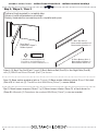
W. Changer Strap x 1
Sangle du Table à Langer x 1
Correa de Cambiador x 1
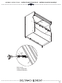
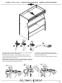
Align the hole in the end of the strap of the Changer Strap (Part W) with the hole in the Top
Shelf. Insert (1) M6x25 mm Bolts (Part R) through a Nylon Washer (Part U), the Changer Strap
and the hole in the Shelf. Add (1) Nylon Washer (Part U) with a Nut (Part V). Hold the Nut with a
Pliers or Adjustable Wrench. Repeat with the other side of the strap as shown.
Aligner le trou au bout de la sangle du Table à Langer (Pièce W) avec le trou de la tablette
supérieure. Insérer (1) boulon M6 x 25 mm (Pièce R) dans une rondelle de nylon (Pièce U),
dans la sangle du Table à Langer et dans la fente qui se trouve sur la tablette. Ajouter (1)
rondelle de nylon (Pièce U) et un écrou (Pièce V). Maintenir l’écrou à l’aide de pinces ou
d’une clé réglable. Répéter les mêmes étapes de l’autre côté de la sangle, tel qu’illustré.
Alinee el agujero del extremo de la correa del cambiador (Pieza W) con el agujero del
Estante Superior. Inserte (1) perno M6x25 mm (Pieza R) a través de una arandela de Nylon
(Pieza U), la correa de cambiador y el agujero del estante. Añada (1) arandela de Nylon
(Pieza U) con una tuerca (Pieza V). Sostenga la tuerca con una llave ajustable o alicate.
Apriete utilizando la llave Allen M4. Repita con el otro lado de la correa.
A pliers or adjustable wrench is required for
assembly.
Des pinces ou une clé anglaise sont
nécessaires pour le montage.
Se necesita unos alicates o una llave
ajustable para ensamblar.
ASSEMBLY INSTRUCTIONS • INSTRUCTIONS DE MONTAGE • INSTRUCCIONES DE MONTAJE
La page est en cours de chargement...

28
Step 12 / Étape 12 / Paso 12
Parts and tools required to complete step
Pièces et outils nécessaires au montage
Piezas y herramientas necesarias para completar este paso
From Step 11
À partir de l’étape 11
Desde el paso 11
P. Changer Pad x 1
Matelas à Langer x 1
Superficie para Cambios x 1
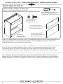
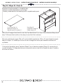
Place the Changer Pad (Part P) onto the Top Shelf (Part G) on top of the attached Strap from
step 11. Be sure the buckle on the strap is over the Pad as shown.
Placer le matelas à Langer (Pièce P) sur la tablette supérieure (Pièce G) par-dessus la sangle
fixée à l’étape 11. Vérifier que la boucle de la sangle se trouve par-dessus le matelas, tel
qu’illustré.
Coloque la Superficie para Cambios (Pieza P) en el estante superior (Pieza G) encima de la
correa del paso 11. Asegurándose que el pasador es encima de la Superficie para Cambios,
tal como se indica.
ASSEMBLY INSTRUCTIONS • INSTRUCTIONS DE MONTAGE • INSTRUCCIONES DE MONTAJE
La page est en cours de chargement...

30
Step 13 / Étape 13 / Paso 13
Final
Final
Final
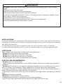
WARNING : FALL HAZARD
ALWAY KEEP CHILD WITHIN ARMS REACH.
Restraint harness system use:
. Place the infant on the changing table foam pad.
. Position the restraint harness over the middle of the infant’s torso and insert the buckled ends into
each other until the lock shut with a click.
. Gently pull the loose end of the strap to lightly snug the restraint harness around the infant.
Maintenance
. Check fasteners periodically for tightness. Do not over tighten. This may cause distortion or
breakage.
Utilisation du système de harnais de sécurité :
. Placer l’enfant sur le matelas mousse de la table à langer.
. Placer le harnais de sécurité au centre du torse de l’enfant et insérer les boucles l’une dans l’autre.
La sangle est bien bouclée lorsque l’on entend un clic sonore.
. Tirer doucement sur la partie lâche de la sangle en vue d’enrouler légèrement le harnais de sécurité
autour de l’enfant.
Entretien :
. Vérifier régulièrement que les attaches sont bien serrées. Ne pas serrer excessivement. Autrement,
la sangle pourrait se casser ou se déformer.
AVERTISSEMENT : DANGER DE CHUTE :
TOUJOURS RESTER À PORTÉE DE MAIN DE L’ENFANT.
Uso del arnés de sujeción
. Coloque al bebé sobre la almohadilla de esponja del cambiador.
. Coloque el arnés de sujeción sobre la parte media del torso del bebé e Inserte los extremos con
seguros entre sí hasta que el seguro se cierre y Haga un sonido de clic.
. Jale con suavidad el extremo suelto de la correa para aumentar levemente la Sujeción del arnés en
el bebé.
Mantenimiento
. Revise las correas periódicamente para verificar su firmeza. No apriete más de La cuenta. Esto
podría causar distorsión o ruptura.
ADVERTENCIA: RIESGO DE CAÍDAS
MANTENGA SIEMPRE AL BEBÉ AL ALCANCE DE SUS MANOS.
ASSEMBLY INSTRUCTIONS • INSTRUCTIONS DE MONTAGE • INSTRUCCIONES DE MONTAJE

31
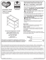
To fasten strap - Push buckle side together be sure buckle is
fully fastened to secure child safely.
Pour boucler la sangle – Insérez les boucles l’une dans
l’autre. Assurez-vous que la sangle est bien bouclée pour
assurer la sécurité de l’enfant.
Para apretar la correa: Una los lados del pasador y seguro
firmemente asegurándose de que esté totalmente ajustado
para así proteger la integridad del niño.
To release, press both tabs and pull apart.
Pour ouvrir, appuyer sur les deux languettes et
retirez les deux boucles.
Para soltar, presione ambas lengüetas y jale.
ASSEMBLY INSTRUCTIONS • INSTRUCTIONS DE MONTAGE • INSTRUCCIONES DE MONTAJE
La page est en cours de chargement...
La page est en cours de chargement...
La page est en cours de chargement...
La page est en cours de chargement...
La page est en cours de chargement...
La page est en cours de chargement...
La page est en cours de chargement...
-
 1
1
-
 2
2
-
 3
3
-
 4
4
-
 5
5
-
 6
6
-
 7
7
-
 8
8
-
 9
9
-
 10
10
-
 11
11
-
 12
12
-
 13
13
-
 14
14
-
 15
15
-
 16
16
-
 17
17
-
 18
18
-
 19
19
-
 20
20
-
 21
21
-
 22
22
-
 23
23
-
 24
24
-
 25
25
-
 26
26
-
 27
27
-
 28
28
-
 29
29
-
 30
30
-
 31
31
-
 32
32
-
 33
33
-
 34
34
-
 35
35
-
 36
36
-
 37
37
-
 38
38


Delta Children 530240-026 Manuel utilisateur
- Taper
- Manuel utilisateur
- Ce manuel convient également à
dans d''autres langues
Documents connexes
-
 Delta Children Gateway 2-in-1 Changing Table & Storage Unit Mode d'emploi
-
 Delta Children Freedom Changing Table Assembly Instructions
-
 Delta Children Essex Changing Table/Bookcase Assembly Instructions
-
 Delta Children 540242-130 Guide d'installation
-
 Delta Children Liberty Changing Table Assembly Instructions
-
 Delta Children Bennington Elite Changing Table Assembly Instructions
-
 Delta Children Fabio Toddler Bed Assembly Instructions
-
 Delta Children 552010-130 Guide d'installation
-
 Delta Children Eclipse Changing Table Assembly Instructions
-
 Delta Children Hanover Park Crib 'N' More Assembly Instructions


