Thermador PALPKITHW5 Guide d'installation
- Catégorie
- Cuisinières
- Taper
- Guide d'installation
Ce manuel convient également à

THERMADOR.COM
Installation
INSTRUCTIONS
Pro Harmony
®
, Pro Grand
®
, and Pro Rangetop Propane (LP) Conversion Kit

THERMADOR.COM
Installation
INSTRUCTIONS
Table of contents (English) ................................................................ 3
Table de matières (Français)............................................................ 19
Índice de materias (Español)............................................................ 35
Models |
Modèles |
Modelos:
PALPKITHW
PALPKITHW5
PALPKITGW
PALPKITGW5
Pro Harmony
®
, Pro Grand
®
, and Pro Rangetop Propane (LP) Conversion Kit

Page. 3
This THERMADOR
®
appliance is made by
BSH Home Appliances Corporation
1901 Main Street, Suite 600
Irvine, CA 92614
Questions?
1-800-735-4328
www.thermador.com
We look forward to hearing from you!
Table of
CONTENTS
Safety ...................................................................................... 4
Important safety instructions .......................................... 4
Propane (LP) gas conversion instructions ............................... 6
Before you begin ............................................................ 6
Checklist.......................................................................... 7
Installation procedure............................................................. 8
Disassembling the rangetop........................................... 8
Converting the regulator to LP....................................... 9
Changing the STAR® burner orifices ............................. 9
Propane (LP) burner orifice conversion tables................ 10
Setting the STAR burner valve screws ............................ 12
Changing the broil orifice, on GAS ranges only............. 13
Changing the bake orifice, on GAS ranges only ............ 14
Checking for gas leaks.................................................... 16
Reassembling the appliance ........................................... 16
Checking the flame and burner performance................. 17
Placing the conversion label ........................................... 18
Support, accessories, and parts..................................back page
Safety
DEFINITIONS
9 WARNING
This indicates that death or serious injuries may occur as a
result of non-observance of this warning.
9 CAUTION
This indicates that minor or moderate injuries may occur as a
result of non-observance of this warning.
NOTICE: This indicates that damage to the appliance or
property may occur as a result of non-compliance with this
advisory.
Note: This alerts you to important information and/or tips.

Page. 4
Safety
9 IMPORTANT SAFETY INSTRUCTIONS
READ AND SAVE THESE INSTRUCTIONS
Please read carefully
Save the original gas parts for possible conversion back in
the future.
Important: Only a qualified service technician or installer
should make this conversion.
Installer: Please leave these instructions with this unit for
the owner.
Owner: Please retain these instructions for future
reference.
This kit is for converting Thermador appliances for
operation with propane (LP) gas. This kit contains orifices
for proper LP conversion for oven bake, broiler, and
STAR
®
burners.
This kit is used to convert select models of Pro Rangetop,
Pro Harmony, and Pro Grand ranges to propane (LP) gas
usage. This kit cannot be used to convert older models of
rangetops or ranges. This kit cannot be used to convert
any other brand of appliance.
WARNING
This conversion kit shall be installed by a
qualified service agency in accordance with the
manufacturer’s instructions and all applicable
codes and requirements of the authority having
jurisdiction. If the information in these
instructions is not followed exactly, a fire,
explosion or production of carbon monoxide
may result causing property damage, personal
injury or loss of life. The qualified service
agency is responsible for the proper installation
of this kit. The installation is not proper and
complete until the operation of the converted
appliance is checked as specified in the
manufacturer’s instructions supplied with the
kit.
For Massachusetts installations
1. Installation must be performed by a qualified or
licensed contractor, plumber, or gas fitter qualified or
licensed by the state, province or region.
2. Shut-off valve must be a “T” handle gas cock.
3. Flexible gas connector must not be longer than 36
inches.
WARNING
If the information in this manual is
not followed exactly, a fire or
explosion may result causing
property damage, personal injury or
death.
-- DO NOT store or use gasoline or other
flammable vapors and liquids in the
vicinity of this or any other appliance.
-- WHAT TO DO IF YOU SMELL GAS
• DO NOT try to light any appliance.
• DO NOT touch any electrical switch.
• DO NOT use any phone in your
building.
• Immediately call your gas supplier
from a neighbor’s phone. Follow the
gas supplier’s instructions.
• If you cannot reach your gas supplier,
call the fire department.
-- Installation and service must be
performed by a qualified installer, service
agency or the gas supplier.

Page. 5
9 IMPORTANT SAFETY INSTRUCTIONS
READ AND SAVE THESE INSTRUCTIONS
The following must be met when testing supply piping
system:
• The appliance and its individual shut-off valve
must be disconnected from the gas supply piping
system at test pressures in excess of 1/2 psig
(3.5 kPa).
• The appliance must be isolated from the gas
supply piping system by closing its individual
manual shut-off valve during any pressure testing
of the gas supply piping system at test pressures
equal to or less than 1/ 2 psig (3.5 kPa).
CAUTION
When connecting the unit to propane gas, make
certain the propane gas tank is equipped with its own
high pressure regulator. The maximum gas pressure to
this appliance is not to exceed 14.0 inches water
column from the propane gas tank regulator.
State of California Proposition 65 Warning:
: WARNING
This product can expose you to chemicals including
vinyl chloride, which is known to the State of California
to cause cancer and birth defects or other
reproductive harm. For more information go to
www.P65Warnings.ca.gov.
WARNING
NEVER leave the gas conversion partially completed.
If the appliance is operated while the gas conversion is
incomplete, high levels of carbon monoxide may be
emitted, or a fire or explosion may occur.
To the service agent
It is important that you know the following BEFORE you
begin the conversion of the appliance.
• Confirm that the gas supply system is available and
ready to use. This is particularly important for new
construction.
• Verify the type of gas supplied to the location. Ensure
that the appliance is connected to the type of gas for
which it is certified.
• You must plan for sufficient time and resources to
perform the conversion process properly and
completely before leaving the job site. Every step
described in these instructions must be performed to
safely convert the appliance for proper operation with
propane (LP) gas. INCOMPLETE OR INADEQUATE
CONVERSION OF THE APPLIANCE CAN CREATE A
SAFETY HAZARD.
Gas and dual fuel ranges converted for propane (LP)
gas and high altitude
The appliance must first be converted for use with
propane (LP) gas before it can be converted for use at
high altitude. It is required that a qualified technician
install the high altitude kit.

Page. 6
Propane (LP) gas conversion instructions
Before you begin
9 CAUTION
Before proceeding with the conversion, shut off the
gas supply to the appliance prior to disconnecting the
electrical power.
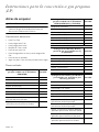
Tools needed
• T-20 torx driver
• 7/16'' box end wrench
• 13/16'' box end wrench
• 7 mm or a 9/32'' socket
• 1/4'' nut driver
• 16 mm hex bit or 5/8'' hex bit
• Adjustable wrench
• Soap and water mixture or leak-check solution
LP gas kit parts included
Gas Pro Harmony ranges with 5 burners
(PRG305WH)
Qty.
Conversion label 1
Foam tape, 1'' piece 1
Screwdriver, 1/8'' x 0.20'' 1
Orifice, 0.73 mm (73) 2
Orifice, 0.90 mm (90) 1
Orifice, 1.05 mm (105) 1
Orifice, 1.15 mm (115) 1
Orifice, 1.34 mm (134), Harmony, main oven
bake
1
Orifice, 1.25 mm (125), Grand and Harmony,
main oven broil
1
Dual fuel Pro Harmony ranges and Pro
Rangetop with 5 burners
(PRD305WH(U/C) or PCG305W)
Qty.
Conversion label 1
Foam tape, 1'' piece 1
Screwdriver, 1/8'' x 0.20'' 1
Orifice, 0.73 mm (73) 2
Orifice, 0.90 mm (90) 1
Orifice, 1.05 mm (105) 1
Orifice, 1.15 mm (115) 1
Dual fuel Pro Harmony and Pro Grand ranges,
and Pro Rangetop with 4 or 6 burners
Qty.
Conversion label 1
Foam tape, 1'' piece 1
Screwdriver, 1/8'' x 0.20'' 1
Orifice, 1.05 mm (105) 3
Orifice, 1.15 mm (115) 3
Orifice, 1.26 mm (126) 1
Gas Pro Harmony and Pro Grand ranges with
4 or 6 burners
Qty.
Conversion label 1
Foam tape, 1'' piece 1
Screwdriver, 1/8'' x 0.20'' 1
Orifice, 1.05 mm (105) 3
Orifice, 1.15 mm (115) 3
Orifice, 1.26 mm (126) 1
Orifice, 1.34 mm (134), Harmony, main oven
bake
1
Orifice, 1.40 mm (140), Grand, main oven bake 1
Orifice, 1.13 mm (113), Grand and Harmony,
aux oven bake
1
Orifice, 1.25 mm (125), Grand and Harmony,
main oven broil
1
Orifice, 0.813 mm (813), Grand and Harmony,
aux oven broil
1

Page. 7
Checklist
Each of the following steps must be completed correctly
for the appliance to function properly. Check off each step
as it is finished.
Pro Harmony gas models
Pro Harmony dual fuel models
Pro Grand gas models
Pro Grand dual fuel models
Ù Step 1
Disassemble the rangetop (page 8).
Ù Step 2
Convert the regulator to LP gas (page 9).
Ù Step 3
Change the STAR® burner orifices according
to your model and the corresponding table
(page 9).
Ù Step 4
Set the valve screws for the STAR burners
(page 12).
Ù Step 5
Check the flame and burner performance
(page 17).
Ù Step 6
Remove the oven door (page 14).
Ù Step 7
Remove the kick and front panels (page 15).
Ù Step 8
Change the main oven broil burner orifice to
the 1.25 mm (125) orifice (page 13).
Ù Step 9
48'' models – change the aux oven broil
burner orifice to the 0.813 mm (813) orifice
(page 13).
Ù Step 10
Change the main oven bake burner orifice to
the 1.34 mm (134) orifice (page 14).
Ù Step 11
48'' models – change the aux oven bake
burner orifice to the 1.13 mm (113) orifice
(page 14).
Ù Step 12
Check the rangetop and oven for gas leaks
(page 16).
Ù Step 13
Reassemble the rangetop, door, kick and
front panels.
Ù Step 14
Place the conversion label (page 18).
Ù Step 1
Disassemble the rangetop (page 8).
Ù Step 2
Convert the regulator to LP gas (page 9).
Ù Step 3
Change the STAR burner orifices according
to your model and the corresponding table
(page 9).
Ù Step 4
Set the valve screws for the STAR burners
(page 12).
Ù Step 5
Check the flame and burner performance
(page 17).
Ù Step 6
Check the rangetop for gas leaks (page 16).
Ù Step 7
Reassemble the rangetop.
Ù Step 8
Place the conversion label (page 18).
Ù Step 1
Disassemble the rangetop (page 8).
Ù Step 2
Convert the regulator to LP gas (page 9).
Ù Step 3
Change the STAR burner orifices according
to your model and the corresponding table
(page 9).
Ù Step 4
Set the valve screws for the STAR burners
(page 12).
Ù Step 5
Check the flame and burner performance
(page 17).
Ù Step 6
Remove the oven door (page 14).
Ù Step 7
Remove the kick and front panels (page 15).
Ù Step 8
Change the main oven bake burner orifice to
the 1.40 mm (140) orifice (page 14).
Ù Step 9
48'' models – change the aux oven bake
burner orifice to the 1.13 mm (113) orifice
(page 14).
Ù Step 10
Change the main oven broil burner orifice to
the 1.25 mm (125) orifice (page 13).
Ù Step 11
48'' models – change the aux oven broil
burner orifice to the 0.813 mm (813) orifice
(page 13).
Ù Step 12
Check the rangetop and oven for gas leaks
(page 16).
Ù Step 13
Reassemble the rangetop, door, kick and
front panels.
Ù Step 14
Place the conversion label (page 18).
Ù Step 1
Disassemble the rangetop (page 8).
Ù Step 2
Convert the regulator to LP gas (page 9).
Ù Step 3
Change the burner orifices according to your
model and the corresponding table
(page 10).
Ù Step 4
Set the valve screws for the STAR burners
(page 16).
Ù Step 5
Check the rangetop for gas leaks (page 16).
Ù Step 6
Reassemble the rangetop.
Ù Step 7
Check the flame and burner performance
(page 17).
Ù Step 8
Place the conversion label (page 18).

Page. 8
Installation procedure
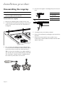
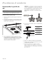
Disassembling the rangetop
9 CAUTION
Shut off the gas supply to the appliance prior to
disconnecting the electrical power.
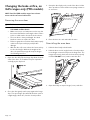
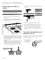
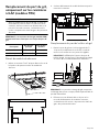
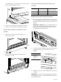
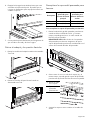
To disassemble the rangetop
1. Remove the rangetop grates and the burner caps.
2. To facilitate the removal of the spill tray, remove the T-
20 torx screws in the front face of the island trim or
backguard.
3. Use a 16 mm hex head bit for burners labeled ‘D’ or
‘F’. Use a 9 mm hex head bit for burners labeled ‘B’ to
remove the burner venturi from each burner base.
TIP: If a 16 mm hex head bit is not readily available, a
5/8'' hex bit can be selected. Alternatively, a bolt with
5/8'' head either “double-nutted” or tightened into
the chuck of a power driver can be used.
4. Disconnect the igniter. Carefully pull up on the burner
base.
5. Carefully remove each burner pedestal.
6. Remove the spill trays by rotating the trays up and out
the back.
7. Remove the heat shield on some models. Some
models have a double-width shield that extends under
adjacent spill tray.
1
2
a. Burner base
b. Electrode
c. Igniter housing
d. Igniter wire
a
b
c
d

Page. 9
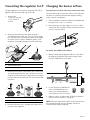
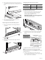
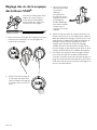
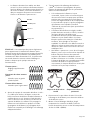
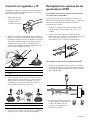
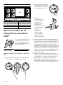
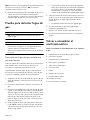
Converting the regulator to LP
The gas regulator is located in the rangetop, left side of
appliance. Exact location will vary per model.
2. Grasp the plastic button stem firmly and pull it
forcefully from the metal cap. The stem snaps snugly
into an indent in the cap and may require a strong pull
to remove. (Hint: it may be helpful to gently “rock”
the plastic stem while pulling it from the metal cap.)
3. Rotate the stem 180° so the letters “LP” on the stem
are upside down when the cap is set flat on its head.
Snap the stem back in place in this position inserting it
into the indent in the metal cap.The stem should snap
into place.
4. Reinstall conversion cap, configured for LP gas, back
into top of the regulator.
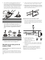
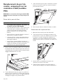
Changing the burner orifices
To prepare the nut driver for burner orifice conversions
The foam tape helps to retain the orifice in the end of the
nut driver so it will not fall inside the appliance during
orifice removal or installation.
1. Trim a small piece of the foam tape provided with this
kit (about 1/4'' x 1/2'' / 6 x 12 mm).
2. Place foam tape over the edge of a 7 mm or a 9/32''
socket with 1/4'' nut driver used to replace the burner
orifices, as shown below.
To replace the STAR
®
burner orifices
1. With the foam tape wrapped nut driver, reach down
through the jet holders and remove the gas orifice
from the STAR burner’s jet holder.
2. Locate the proper STAR burner
orifices included with the kit.
Orifices are stamped with the
orifice diameter size on the side.
3. Replace orifices as indicated in “Propane (LP) burner
orifice conversion tables” on page 10.
NOTE: All of the replacement orifices in the conversion kit
have straight threads (not pipe threads) and do not
require thread sealing compound.
1. Remove the
conversion cap with
a 7/8'' socket or
wrench.
a. Spring
b. Plastic button stem
c. Gasket
a. Natural gas
b. LP gas
a
b
c
a
b
1
2

Page. 10
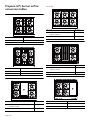
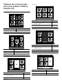
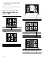
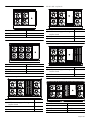
Propane (LP) burner orifice
conversion tables
Model 304
(1)105 (3)105
(2)115 (4)115
Model 305
(1) 73 (4) 73
(2) 115 (5) 105
(3) 90
Model 364 with griddle
(1) 105 (4) 105
(2) 115 Pro Harmony and Rangetop
126 Pro Grand
(5) 115
(3) —
44
11
22
33
33
55
11
22
44
33
55
11
22
44
Model 366
(1) 105 (4) 115
(2) 115 Pro Harmony and Rangetop
126 Pro Grand
(5) 105
(3) 105 (6) 115
Model 364 with grill
(1) 105 (4) 105
(2) 115 Pro Harmony and Rangetop
126 Pro Grand
(5) 115
(3) —
Model 364 with induction
(1)105 (4)115
(2)126 (5)—
(3) 105
33
44
66
11
22
55
33
55
11
22
44
55
44
11
22
33

Page. 11
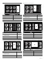
Model 486 with induction
(1) 105 (5) 105
(2) 126 (6) 115
(3) 105 (7) —
(4) 115
Model 486 with grill
(1) 105 (5) —
(2) 115 Pro Harmony and Rangetop
126 Pro Grand
(6) 105
(3) 105 (7) 115
(4) 115
Model 486 with griddle
(1) 105 (5) —
(2) 115 Pro Harmony and Rangetop
126 Pro Grand
(6) 105
(3) 105 (7) 115
(4) 115
33
44
66
11
22
55
77
33
44
77
11
22
66
55
33
44
77
11
22
66
55
Model 486 with griddle and grill
(1) 105 (4) 115
(2) 115 Pro Harmony and Rangetop
126 Pro Grand
(5) —
(3) 105 (6) —
Model 606 with griddle and grill
(1)105 (5)—
(2)126 (6)—
(3)105 (7)105
(4)115 (8)115
Model 606 with griddle and grill
(1)105 (5)—
(2)126 (6)105
(3)105 (7)115
(4) 115
33
44
11
22
55
66
33
44
77
88
11
22
55
66
33
44
66
77
11
22
55

Page. 12
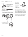
Setting STAR
®
burner valve
screws
To set the burner valve screws
1. Remove the knob from the valve stem by slowly
pulling knob straight out, away from the control panel.
4. Adjust the valve screw by turning the valve screw
about an 1/8
th
turn. Turn the screw clockwise to
reduce simmer flame size. Turn the screw counter-
clockwise to make the simmer flame larger. Adjust the
valve screw as little as required to reach satisfactory
simmer results. Due to normal fluctuations in gas
pressure, over-adjustment of valve screw may affect
flame stability.
5. Perform a gas leak test of each orifice and associated
supply tube fittings. See “Checking for gas leaks” on
page 16. Leak-checking should occur after the orifice
conversion is complete, and before the burner is
reassembled and tested.
A flat-head screwdriver with an
1/8" [3.0 mm] wide, .020"
[0.50 mm] thickness tip
(included) is used to adjust the
valve screws.
2. Remove the bezel-mounting
screw located to the right of
the valve stem, using a T-20
torx screwdriver.
3. Insert a 1/8'' flat-
blade screwdriver
into the hole of the
bezel mounting
screw. Access to the
valve screws through
clearance hole in the
spark module. You
should feel the
engagement of the
screwdriver and the
valve screw.

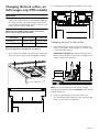
Page. 13
Changing the broil orifice, on
GAS ranges only (PRG models)
9 CAUTION
After the replacement of the broiler orifice, and
before reassembly of the back panel and backguard to
the range, perform a brief gas leakage check of the
orifice and associated fittings, per the “Check for Gas
Leaks” section of these instructions.
NOTE: Dual fuel (PRD models) ranges have electric
ovens and do not have a broil orifice.
Removing the backguard assembly
1. Use a T-20 torx screwdriver to remove the screws from
the front and rear panel of the backguard assembly.
2. Carefully lift the backguard assembly from the range.
Changing the broil burner orifice
1. Remove broil orifice using a 7/16'' box end wrench,
while restraining the elbow fitting from rotation using
a small adjustable wrench.
IMPORTANT: DO NOT bend the broil burner orifice
bracket. Ensure that the broiler orifice is aligned to the
center of the burner tube inlet.
NOTE: The replacement broil orifices have straight
threads (not tapered threads) and DO NOT require thread
sealing compound.
2. Perform a gas leakage check of the orifice and
associated supply tube fittings, per the “Check for gas
leaks” section of these instructions.
Description Main oven broil Aux oven broil
Pro Grand 1.25 mm (125) 0.813 mm (813)
Pro Harmony 1.25 mm (125) 0.813 mm (813)

Page. 14
Changing the bake orifice, on
GAS ranges only (PRG models)
NOTE: Dual fuel (PRD models) ranges have electric
ovens and do not have a bake orifice.
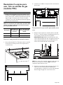
Removing the oven door
9 CAUTION
• USE CAUTION WHEN REMOVING THE DOOR.
THE DOOR IS VERY HEAVY.
• Make sure oven is cool and power to the oven has
been turned off before removing the door. Failure
to do so could result in electrical shock or burns.
• The oven door is heavy and fragile. Use both
hands to remove or replace the door.
• Failure to grasp the oven door firmly and properly
could result in personal injury and product
damage.
• With the door off, never release the levers and try
to close the hinges. Without the weight of the
door, the powerful springs will snap the hinges
closed with great force.
1. Open the door fully. Flip the hinge clips down for both
sides of the door. A screwdriver may be required to
carefully pry the clip back.
2. Close the door gently until it stops against the hinge
clips. The open hinge clips will hold the door open at
a slight angle, about 30°, from the closed position.
3. Grasp the door firmly on the ends of the door. Lift the
door up and out. There will be some spring resistance
to overcome.
4. Place the door in a safe and stable location.
Reinstalling the oven door
1. Hold the door firmly in both hands.
2. Hold the door at a 30° angle from the closed position.
Insert hinges centered evenly into the hinge slots. The
hinges will securely hook into the slots when properly
installed. DO NOT force, bend or twist the door.
3. Open door fully to expose hinges, levers, and slots.

Page. 15
4. Flip the hinge forward until seated on the bracket. A
screwdriver may be required to carefully push the clip
back.
5. Close and open the door slowly to ensure it is
correctly and securely in place.
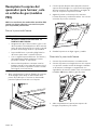
Removing the kick and front panels
1. Remove the kick panel screws using a T-20 torx
screwdriver.
2. Remove the front panel screws using a T-20 torx
screwdriver.
Changing the bake burner orifice
To change the bake burner orifice
1. Remove the bake gas line using a 13/16'' box end
wrench, while restraining the elbow fitting from
rotation using an adjustable wrench.
IMPORTANT: DO NOT bend the bake burner tube or
shutter. Ensure that the bake orifice is aligned to the
center of the burner tube inlet.
2. Hand twist the orifice elbow (a) while restraining the
bake orifice (b) from rotation using an adjustable
wrench.
3. Replace the orifices as indicated in the tables above.
NOTE: The replacement broil orifices have straight
threads (not tapered threads) and DO NOT require thread
sealing compound.
4. Perform a gas leakage check of the orifice and
associated supply tube fittings, per the “Check for gas
leaks” section of these instructions.
Description Main oven bake Aux oven bake
Pro Grand 1.40 mm (140) 1.13 mm (113)
Pro Harmony 1.34 mm (134) 1.13 mm (113)
a. Orifice elbow
b. Bake orifice
b
a

Page. 16
Checking for gas leaks
9 WARNING
DO NOT use a flame of any kind to check for gas
leaks.
9 CAUTION
DO NOT spray water solution onto exposed electrical
devices. If solution does drip onto electrical
components, shut the power off before wiping off the
parts.
Gas leak check using a liquid solution
The replacement orifices in the high-altitude conversion
kit, have straight threads (not tapered threads) and do not
require thread sealing compound.
Leak-checking should occur after the orifices are replaced,
and before the appliance is reassembled and tested.
1. Make sure that the orifice has been tightened and that
all valves and controls are in the OFF position.
2. Turn on electric and gas supplies.
3. Spray a generous amount of soap and water
mixture—or other solution designed for checking gas
leaks—on the threaded junction at the base of the
orifice, the elbow fitting, and gas tube compression
nut. (A 25% dishwashing liquid to water mixture is
effective for this.) Avoid spraying electrical devices.
4. Turn the mode knob and the oven temperature knob
to “BROIL” while blocking the broil orifice hole with a
soft pencil eraser, your finger, or something similar.
• There will be a delay of approximately 45 to 90
seconds as the safety valve coil heats to release
the valve’s actuator. A single pop noise can usually
be heard as the broiler’s safety valve opens.
5. Monitor the base of the orifice junction, elbow fitting,
and compression nut to see if bubbles are forming
anywhere around the connections.
• Bubbles forming are indications of gas leaks.
6. If appliance leaks, repair all gas leaks immediately.
7. Repeat for the bake orifice.
8. Turn off the gas and electric supplies.
Reassembling the appliance
Reassemble the appliance in the following order:
1. Rangetop heat shield, if applicable
2. Spill trays
3. Burner pedestals
4. Burner bases
5. Burner caps
6. Backguard
7. Grates
8. Conversion label placement
9. Front panel, if applicable
10. Kick panel, if applicable
11. Oven door, if applicable

Page. 17
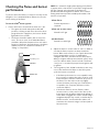
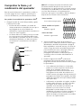
Checking the flame and burner
performance
To observe the burner flames, it may be necessary to turn
off lights or close window blinds to darken the room for
easier viewing of the flame.
To test the STAR
®
burner ignition
1. Push in the burner control knob and turn it to “HI”.
• The igniter electrode and spark module will
produce a clicking sound. Once the air has been
purged from the supply lines, the burner should
light within four seconds.
• The flames should be stable, with no excessive
noise. The inner cones of the individual flames
should be defined and separate from each other.
Portions of the flame, along the burner, should not
exhibit excessive or continuous indications of
“lifting” or “lazy flame”.
NOTE: It is normal for slight yellow tipping of the flames
to appear after a few minutes of operation using Propane
(LP) gas. Orange-colored streaks in the flame are
produced from burning airborne debris; this is normal
during initial start up and should dissipate within a few
minutes of operation.
2. Adjust the burner’s control valve to “LO” or “SIM” to
see that the flame continues to wrap around the
burner. Blow out the flame, or use a quick fan motion
from a writing tablet or piece of cardboard to
extinguish the flame, and then observe the burner’s
ability to reignite and wrap around (also called “carry-
over”) the burner within several seconds. This flame
“carry-over” is essential for proper burner ignition and
re-ignition.
3. Test re-ignition of the “XLO
®
” and observe the carry-
over of the small simmer flames as the XLO system
cycles the burners on and off.
• If the flame performance is not acceptable it may
be necessary to readjust the valve screw for a top
burner that does not have sufficient carry-over of
the flame. Turn the valve screw very slightly
counter-clockwise until carry-over of the flame is
acceptable. (See “Propane (LP) burner orifice
conversion tables”).
• If the burner flame is uneven, flutters, makes
excessive noise, or lifts, some of the slots in the
burner base may be blocked with food spillage or
other debris. Clogged slots can be cleared using a
straightened paper clip, needle, or similar object.
Hard-to-remove, encrusted food or debris can
sometimes be removed using a steel wool pad or
fine wire brush.
Dark blueDark blueDark blue
Secondary coneSecondary coneSecondary cone
Light blueLight blueLight blue
Primary conePrimary conePrimary cone
Yellow flames:
Further adjustment is
required.
Yellow tips on outer cones:
Normal for LP gas
Soft blue flames:
Normal for natural gas

Page. 18
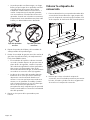
• Burner flames that are “lazy”, with excessively-
long flames, can be created by an incorrectly
fitted burner cap—from which many of the outer
mantles of the individual flames will tend to
“coalesce” or blend together. Verify that the
burner cap is seated properly on its burner base.
The cap should fit reasonably flat when correctly-
positioned on the base and not rock significantly.
4. Repeat the ignition and flame test procedures for
each rangetop burner.
5. Test gas broil ignition (GAS range only). Turn on the
mode knob and the oven temperature knob to
“BROIL”.
• The hot-surface igniter will attempt to light the
broiler after approximately 45 to 90 seconds, as
the safety valve coil heats to open. Once the air
has been purged from the gas supply line, the
broiler should light within four (4) seconds.
• The ceramic tiles of the burner should glow red
hot (infrared) after several minutes of operation. If
after several minutes with the burner lit, the
broiler only has a small amount of red glow (and
burns mostly with blue flame floating on the
burner surface), check that the broiler orifice is
aligned to the center of the burner tube inlet.
6. Repeat for the bake burners.
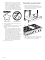
Placing the conversion label
1. For proper identification and evidence of the
appliance’s conversion for propane (LP) gas operation,
affix the provided conversion label in a location next
to the rating labels on the appliance.
2. After placing the conversion label, use a permanent
marker to fill-in the date, name, and address of your
service organization on the conversion label.
Correct burner cap Incorrect burner cap
Star
®
Star
®

Page. 19
Cet appareil électroménager de THERMADOR
TM
est fait par BSH Home Appliances LtD
6696 Financial Drive, Unit 3
Mississauga, ON L5N 7J6
Des questions?
1-800-735-4328
www.thermador.ca
Nous attendons de vos nouvelles!
Table des
MATIÈRES
Sécurité................................................................................... 20
Consignes de sécurité importantes ................................ 20
Directives de la trousse de conversion au gaz propane (PL).. 22
Avant de commencer...................................................... 22
Liste de vérification......................................................... 23
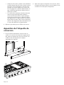
Procédure d’installation.......................................................... 24
Démontage de la table de cuisson................................. 24
Conversion du régulateur pour utilisation avec PL......... 24
Remplacement des ports de brûleur STAR® ................. 25
Tableaux de conversion des ports pour brûleurs
STAR au propane (LP)..................................................... 26
Réglage des vis de la soupape des brûleurs STAR......... 28
Remplacement du port du gril, uniquement sur
les cuisinières à GAZ (modèles PRG).............................. 29
Remplacement du port de cuisson, uniquement sur l
es cuisinières à GAZ (modèles PRG)............................... 30
Inspection des fuites de gaz ........................................... 32
Remontage de l’appareil ................................................ 32
Vérification du rendement de la flamme et du brûleur .. 32
Apposition de l’étiquette de conversion........................ 24
Soutien, pièces et accessoires................................page arrière
Définitions de
SÉCURITÉ
9 AVERTISSEMENT
Ceci indique que le non respect de cet avertissement peut
entraîner des blessures graves, voire la mort.
9 ATTENTION
Ceci indique que le non respect de cet avertissement peut
entraîner des blessures légères ou modérées.
NOTICE : Ceci indique que la non-conformité à cet avis de
sécurité peut entraîner des dégâts à l'appareil ou à la propriété.
Note : Ceci vous avertit que d'importantes informations et/ou
conseils sont fournis.

Page. 20
Sécurité
9 CONSIGNES DE SÉCURITÉ IMPORTANTES
LIRE ET CONSERVER CES DIRECTIVES
Veuillez lire attentivement
Conservez les pièces originales du modèle à gaz dans
l’éventualité d’une reconversion future.
Important : Seul un technicien ou un installateur qualifié
en réparation peut procéder à cette conversion.
Installateur : Prière de laisser les directives avec cet
appareil à l’intention du propriétaire.
Propriétaire : Prière de conserver les directives pour
pouvoir s’y référer ultérieurement.
Cette trousse permet de convertir les appareils
Thermador pour qu’ils fonctionnent au gaz propane
(pétrole liquéfié - PL). Cette trousse renferme des ports
permettant la bonne conversion au PL du four, du gril et
des brûleurs STAR
®
.
Cette trousse sert à convertir certains modèles de table
de cuisson Pro et de cuisinières Pro Harmony et Pro Grand
à un fonctionnement au gaz propane (PL). Elle ne peut pas
être utilisée pour convertir d’anciens modèles de tables
de cuisson ou de cuisinières. Cette trousse ne peut pas
être utilisée pour convertir toute autre marque d’appareil.
AVERTISSEMENT
Cette trousse de conversion doit être installée
par une agence de réparation qualifiée en
conformité aux directives du fabricant et de
tous les autres codes et toutes les exigences en
vigueur de l’autorité ayant juridiction. Si les
directives ne sont pas suivies à la lettre, il y a un
risque d’incendie, d’explosion ou de
génération de monoxyde de carbone pouvant
entraîner des dommages matériels, des
blessures ou une perte de vie. L’agence de
réparation qualifiée est responsable de la
bonne installation de cette trousse.
L’installation n’est pas jugée terminée et
adéquate jusqu’à ce que l’on ait testé l’appareil
converti comme précisé dans les directives du
fabricant fournies avec la trousse.
Pour les installations au Massachusetts
1. L’installation doit être exécutée par un entrepreneur,
un plombier ou un ajusteur d’appareils à gaz qualifié
ou autorisé par l’État, la province ou la région.
2. Le robinet d’arrêt doit être un robinet à gaz avec une
poignée en T.
3. Le connecteur à gaz souple ne doit pas dépasser
36 pouces (914 mm).
AVERTISSEMENT
Si les directives du présent manuel
ne sont pas suivies à la lettre, il y a
un risque d’incendie ou d’explosion
pouvant entraîner des dommages
matériels, des blessures ou la mort.
-- NE PAS conserver ou utiliser de l’essence
ou d’autres liquides et vapeurs
inflammables à proximité de cet appareil
ou de tout autre appareil.
-- QUE FAIRE SI VOUS PERCEVEZ UNE
ODEUR DE GAZ
• NE PAS essayer de mettre un appareil
électroménager sous tension.
• NE PAS toucher d’interrupteur de
courant électrique.
• NE PAS utiliser de téléphone dans
l’édifice.
• Communiquer immédiatement avec le
fournisseur de gaz depuis l’appareil
téléphonique d’un voisin. Respecter
les directives du fournisseur de gaz.
• S’il s’avère impossible de joindre le
fournisseur de gaz, communiquer avec
les pompiers.
-- Utiliser les services d’un installateur ou
d’une agence de réparations qualifiés ou
le fournisseur de gaz pour procéder à
l’installation et aux réparations.
La page est en cours de chargement...
La page est en cours de chargement...
La page est en cours de chargement...
La page est en cours de chargement...
La page est en cours de chargement...
La page est en cours de chargement...
La page est en cours de chargement...
La page est en cours de chargement...
La page est en cours de chargement...
La page est en cours de chargement...
La page est en cours de chargement...
La page est en cours de chargement...
La page est en cours de chargement...
La page est en cours de chargement...
La page est en cours de chargement...
La page est en cours de chargement...
La page est en cours de chargement...
La page est en cours de chargement...
La page est en cours de chargement...
La page est en cours de chargement...
La page est en cours de chargement...
La page est en cours de chargement...
La page est en cours de chargement...
La page est en cours de chargement...
La page est en cours de chargement...
La page est en cours de chargement...
La page est en cours de chargement...
La page est en cours de chargement...
La page est en cours de chargement...
La page est en cours de chargement...
La page est en cours de chargement...
-
 1
1
-
 2
2
-
 3
3
-
 4
4
-
 5
5
-
 6
6
-
 7
7
-
 8
8
-
 9
9
-
 10
10
-
 11
11
-
 12
12
-
 13
13
-
 14
14
-
 15
15
-
 16
16
-
 17
17
-
 18
18
-
 19
19
-
 20
20
-
 21
21
-
 22
22
-
 23
23
-
 24
24
-
 25
25
-
 26
26
-
 27
27
-
 28
28
-
 29
29
-
 30
30
-
 31
31
-
 32
32
-
 33
33
-
 34
34
-
 35
35
-
 36
36
-
 37
37
-
 38
38
-
 39
39
-
 40
40
-
 41
41
-
 42
42
-
 43
43
-
 44
44
-
 45
45
-
 46
46
-
 47
47
-
 48
48
-
 49
49
-
 50
50
-
 51
51


Thermador PALPKITHW5 Guide d'installation
- Catégorie
- Cuisinières
- Taper
- Guide d'installation
- Ce manuel convient également à
dans d''autres langues
- español: Thermador PALPKITHW5 Guía de instalación
- português: Thermador PALPKITHW5 Guia de instalação
Documents connexes
-
Thermador PALPKITGGW Manuel utilisateur
-
-
-
-
-
-
Thermador PAALTKITGW Guide d'installation
-
-
-