Yard Machines Y26SS Manuel utilisateur
- Catégorie
- Coupe-herbe
- Taper
- Manuel utilisateur

Operator’s Manual
SAVE THESE INSTRUCTIONS
For service call 1-800-800-7310 in the United States, or
1-800-668-1238 in Canada to obtain a list of authorized service
dealers near you. For more details about your unit, visit our
website at www.yardmachines.com.
DO NOT RETURN THE UNIT TO THE RETAILER. PROOF OF
PURCHASE WILL BE REQUIRED FOR WARRANTY
SERVICE.
THIS PRODUCT IS COVERED BY ONE OR MORE U.S.
PATENTS. OTHER PATENTS PENDING.
Service on this unit both within and after the warranty period
should be performed only by an authorized and approved
service dealer.
All information, illustrations, and specifications in this manual
are based on the latest product information available at the
time of printing. We reserve the right to make changes at any
time without notice.
Copyright© 2006 MTD SOUTHWEST INC, All Rights Reserved.
WARNING: When using the unit, you must follow
the safety rules. Please read these instructions
before operating the unit in order to ensure the
safety of the operator and any bystanders. Please
keep these instructions for later use.
SPARK ARRESTOR NOTE
NOTE: For users on U.S. Forest Land and in the states of
California, Maine, Oregon and Washington. All U.S. Forest
Land and the state of California (Public Resources Codes 4442
and 4443), Oregon and Washington require, by law that certain
internal combustion engines operated on forest brush and/or
grass-covered areas be equipped with a spark arrestor,
maintained in effective working order, or the engine be
constructed, equipped and maintained for the prevention of
fire. Check with your state or local authorities for regulations
pertaining to these requirements. Failure to follow these
requirements could subject you to liability or a fine. This unit is
factory equipped with a spark arrestor. If it requires
replacement, ask your LOCAL SERVICE DEALER to install the
Accessory Part #791-180890 Spark Arrestor Kit.
CALIFORNIA PROPOSITION 65 WARNING
P/N 769-01951A (12/06)
TABLE OF CONTENTS
Service Information . . . . . . . . . . . . . . . . . . . . . . . . . . . . . .1
Rules for Safe Operation . . . . . . . . . . . . . . . . . . . . . . . . . .2
Oil and Fuel Information . . . . . . . . . . . . . . . . . . . . . . . . . . .3
Assembly Instructions . . . . . . . . . . . . . . . . . . . . . . . . . . . .4
Know Your Unit . . . . . . . . . . . . . . . . . . . . . . . . . . . . . . . . .4
Starting/Stopping Instructions . . . . . . . . . . . . . . . . . . . . . .5
Operating Instructions . . . . . . . . . . . . . . . . . . . . . . . . . . . .6
Maintenance and Repair Instructions . . . . . . . . . . . . . . . .7
Cleaning and Storage . . . . . . . . . . . . . . . . . . . . . . . . . . .13
Troubleshooting Chart . . . . . . . . . . . . . . . . . . . . . . . . . . .14
Specifications . . . . . . . . . . . . . . . . . . . . . . . . . . . . . . . . .15
Warranty Information . . . . . . . . . . . . . . . . . . . . . . . . .17-18
Parts List . . . . . . . . . . . . . . . . . . . . . . . . . . . . . . . . . . . .E17
WARNING
THE ENGINE EXHAUST FROM THIS PRODUCT CONTAINS
CHEMICALS KNOWN TO THE STATE OF CALIFORNIA TO
CAUSE CANCER, BIRTH DEFECTS OR OTHER
REPRODUCTIVE HARM.
4-Cycle Gasoline Trimmer
Y26SS

2
READ ALL INSTRUCTIONS
BEFORE OPERATING
• Read the instructions carefully. Be familiar with the controls
and proper use of the unit.
• Do not operate this unit when tired, ill, or under the influence
of alcohol, drugs, or medication.
• Children and teens under the age of 15 must not use the
unit, except for teens guided by an adult.
• All guards and safety attachments must be installed properly
before operating the unit.
• Inspect the unit before use. Replace damaged parts. Check
for fuel leaks. Make sure all fasteners are in place and secure.
Replace parts that are cracked, chipped, or damaged in any
way. Do not operate the unit with loose or damaged parts.
• Carefully inspect the area before starting the unit. Remove
all debris and hard or sharp objects such as glass, wire, etc.
• Be aware of the risk of injury to the head, hands and feet.
• Clear the area of children, bystanders, and pets. At a
minimum, keep all children, bystanders, and pets outside a
50 feet (15 m.) radius; there still may be a risk to bystanders
from thrown objects. Bystanders should be encouraged to
wear eye protection. If you are approached, stop the unit
immediately.
• Use only 0.080 inch, 2.03 mm diameter original equipment
manufacturer replace-ment line. Never use metal-reinforced
line, wire or rope. These can break off and become
dangerous projectiles.
• Squeeze the throttle control and check that it returns
automatically to the idle position. Make all adjustments or
repairs before using unit.
SAFETY WARNINGS FOR GAS UNITS
• Store fuel only in containers specifically designed and
approved for the storage of such materials.
• Avoid creating a source of ignition for spilled fuel. Do not
start the engine until fuel vapors dissipate.
• Always stop the engine and allow it to cool before filling the
fuel tank. Never remove the fuel tank cap or add fuel when
the engine is hot. Never operate the unit without the fuel cap
securely in place. Loosen the fuel tank cap slowly to relieve
any pressure in the tank.
• Add fuel in a clean, well-ventilated outdoor area where there
are no sparks or flames. Remove the fuel cap slowly, and
only after the engine stops. Do not smoke while fueling.
Wipe up any spilled fuel from the unit immediately.
• Avoid creating a source of ignition for spilled fuel. Do not
start the engine until fuel vapors dissipate.
• Move the unit at least 30 feet (9.1 m) from the fueling source
and site before starting the engine. Do not smoke. Keep
sparks and open flames away from the area while adding
fuel or operating the unit.
WHILE OPERATING
• Never start or run the unit inside a closed room or building.
Breathing exhaust fumes can be fatal. Operate this unit only
in a well-ventilated outdoor area.
• Wear safety glasses or goggles that meet ANSI Z87.1
standards and are marked as such. Wear ear/hearing
protection when operating this unit. Wear a face or dust
mask if the operation is dusty.
• Wear heavy long pants, boots, gloves and a long sleeve
shirt. Do not wear loose clothing, jewelry, short pants,
sandals or go barefoot. Secure hair above shoulder level.
• The cutting attachment shield must always be in place while
operating the unit as a trimmer. Do not operate unit without
both trimming lines extended, and the proper line installed. Do
not extend the trimming line beyond the length of the shield.
• This unit has a clutch. The cutting attachment remains
stationary when the engine is idling. If it does not, have the
unit adjusted by an authorized service technician.
• Adjust the handle to your size in order to provide the best grip.
• Be sure the cutting attachment is not in contact with
anything before starting the unit.
• Use the unit only in daylight or good artificial light.
• Avoid accidental starting. Be in the starting position whenever
pulling the starter rope. The operator and unit must be in a stable
position while starting. Refer to Starting/Stopping Instructions.
• Use the right tool. Only use this tool for its intended purpose.
• Do not overreach. Always keep proper footing and balance.
• Always hold the unit with both hands when operating. Keep
a firm grip on both handles or grips.
• Keep hands, face, and feet at a distance from all moving
parts. Do not touch or try to stop the cutting attachment
when it rotates.
• Do not touch the engine, gear housing or muffler. These
parts get extremely hot from operation, even after the unit is
turned off.
• Do not operate the engine faster than the speed needed to
cut, trim or edge. Do not run the engine at high speed when
not cutting.
• Always stop the engine when cutting is delayed or when
walking from one cutting location to another.
• If you strike or become entangled with a foreign object, stop
the engine immediately and check for damage. Do not
operate before repairing damage. Do not operate the unit
with loose or damaged parts.
• Stop the unit, switch the engine to off, and disconnect the
spark plug for maintenance or repair.
• Use only original equipment manufacturer replacement parts
and accessories for this unit. These are available from your
authorized service dealer. Use of any unauthorized parts or
accessories could lead to serious injury to the user, or
damage to the unit, and void your warranty.
• Keep unit clean of vegetation and other materials. They may
become lodged between the cutting attachment and shield.
• To reduce fire hazard, replace a faulty muffler and spark
arrestor. Keep the engine and muffler free from grass,
leaves, excessive grease or carbon build up.
OTHER SAFETY WARNINGS
• Never store a fueled unit inside a building where fumes may
reach an open flame or spark.
• Allow the engine to cool before storing or transporting. Be
sure to secure the unit while transporting.
• Store the unit in a dry area, locked up or up high to prevent
unauthorized use or damage, out of the reach of children.
• Never douse or squirt the unit with water or any other liquid.
Keep handles dry, clean and free from debris. Clean after
each use, see Cleaning and Storage instructions.
• Keep these instructions. Refer to them often and use them
to instruct other users. If you loan someone this unit, also
loan them these instructions.
SAVE THESE INSTRUCTIONS
RULES FOR SAFE OPERATION
• IMPORTANT SAFETY INSTRUCTIONS •
WARNING: Gasoline is highly flammable, and its
vapors can explode if ignited. Take the following
precautions:

3
RULES FOR SAFE OPERATION
SYMBOL MEANING
• ON/OFF STOP CONTROL
ON / START / RUN
• WARNING - READ OPERATOR'S MANUAL
Read the operator’s manual(s) and follow all warnings
and safety instructions. Failure to do so can result in
serious injury to the operator and/or bystanders.
SAFETY AND INTERNATIONAL SYMBOLS
This operator's manual describes safety and international symbols and pictographs that may appear on this product. Read the
operator's manual for complete safety, assembly, operating and maintenance and repair information.
• ON/OFF STOP CONTROL
OFF or STOP
SYMBOL MEANING
• SAFETY ALERT SYMBOL
Indicates danger, warning or caution. May be used
in conjunction with other symbols or pictographs.
• WEAR EYE AND HEARING PROTECTION
WARNING: Thrown objects and loud noise can
cause severe eye injury and hearing loss. Wear eye
protection meeting ANSI Z87.1 standards and ear
protection when operating this unit. Use a full face
shield when needed.
• KEEP BYSTANDERS AWAY
WARNING: Keep all bystanders, especially
children and pets, at least 50 feet (15 m) from the
operating area.
• THROWN OBJECTS AND ROTATING CUTTER
CAN CAUSE SEVERE INJURY
WARNING: Do not operate without the cutting
attachment shield in place. Keep away from the
rotating cutting attachment.
• HOT SURFACE WARNING
Do not touch a hot muffler, gear housing or cylinder.
You may get burned. These parts get extremely hot
from operation. They remain hot for a short time after
the unit is turned off.
• UNLEADED FUEL
Always use clean, fresh unleaded fuel
• OIL
Refer to operator’s manual for the proper type of
oil.
• SHARP BLADE
WARNING: Sharp blade on cutting attachment
shield. To prevent serious injury, do not touch the
line cutting blade.
• CHOKE CONTROL
1. • FULL choke position
2. • PARTIAL choke position
3. • RUN choke position
OIL AND FUEL INFORMATION
RECOMMENDED OIL TYPE
Using the proper type and weight of oil in the crankcase is
extremely important. Check the oil before each use and
change the oil regularly. Failure to use the correct oil, or using
dirty oil, can cause premature engine wear and failure.
Use a high-quality SAE 30 weight oil of API (American
Petroleum Institute) service class SF, SG, SH.
ADDING OIL TO CRANKCASE: INITIAL USE
NOTE: This unit is shipped without oil. In order to avoid
damage to the unit, put oil in the crankcase before you
attempt to start the unit.
Your unit is supplied with one 3.04
fluid oz. (90 ml.) bottle of SAE 30
SF, SG, SH oil (Fig. 1).
NOTE: Save the bottle of oil. It
can be used to measure the
correct amount during future
oil changes. See Changing
the Oil.
1. Unscrew the top of the bottle of oil and remove the paper
WARNING: OVERFILLING OIL CRANKCASE MAY
CAUSE SERIOUS PERSONAL INJURY. Check and
maintain the proper oil level in the crank case; it is
important and cannot be overemphasized. Check the
oil before each use and change it as needed. See
Changing the Oil.
Fig. 1
Funnel
Spout
seal covering the
opening. Replace the
top. Next, cut the tip off
the funnel spout (Fig. 1).
2. Place the unit on a flat
level surface (Fig. 2).
3. Remove the dipstick from
the crankcase (Fig. 3).
4. Pour the entire bottle
of oil into the oil fill
hole (Fig. 3).
NOTE: Never add oil to
the fuel or fuel tank.
5. Wipe up any oil that
may have spilled and
reinstall the oil fill plug/
dipstick.
Check oil before each use and change as needed. Refer to
Checking the Oil Level.
RECOMMENDED FUEL TYPE
Old fuel is the primary reason for improper unit performance.
Be sure to use fresh, clean, unleaded gasoline.
NOTE: This is a four cycle engine. In order to avoid damage to
the unit, do not mix oil with gasoline.
Fig. 2
Oil Fill
Oil Fill Plug/
Dipstick
Oil Fill Hole
Fig. 3
O-Ring

4
Cutting
Attachment
Shield
Fuel
Cap
Throttle
Control
J-Handle
Cutting
Attachment
Shaft Grip
Primer
Bulb
Oil Fill Plug / Dipstick
Choke
Lever
Spark
Plug
Shaft
Housing
Starter Rope Grip
Line
Cutting
Blade
Spark
Plug
Muffler
Muffler Guard
Spark Arrestor
On/Off Stop
Control
KNOW YOUR UNIT
Air Filter
Cover
OIL AND FUEL INFORMATION
ASSEMBLY INSTRUCTIONS
Definition of Blended Fuels
Today's fuels are often a blend of gasoline and oxygenates
such as ethanol, methanol or MTBE (ether). Alcohol-blended
fuel absorbs water. As little as 1% water in the fuel can make
fuel and oil separate or form acids when stored. Use fresh fuel
(less than 60 days old), when using alcohol-blended fuel.
Using Blended Fuels
If you choose to use a blended fuel, or its use is unavoidable,
follow recommended precautions:
• Always use fresh unleaded gasoline
• Use the fuel additive STA-BIL
®
or an equivalent
• Drain tank and run the engine dry before storing unit
Using Fuel Additives
The use of fuel additives, such as STA-BIL
®
Gas Stabilizer or
an equivalent, will inhibit corrosion and minimize the formation
of gum deposits. Using a fuel additive can keep fuel from
forming harmful deposits in the carburetor for up to six (6)
months. Add 0.8 oz. (23 ml.) of fuel additive per gallon of fuel
according to the instructions on the container. NEVER add fuel
additives directly to the unit's gas tank.
FUELING THE UNIT
1. Remove the fuel cap (Fig. 4).
2. Place the gas container’s spout into the fill hole on the fuel
tank (Fig. 4) and fill the tank.
NOTE: Do not overfill the tank.
3. Wipe up any gasoline that may have spilled.
4. Reinstall the fuel cap.
5. Move the unit at least 30 ft. (9.1 m) from the fueling source
and site before starting the engine.
NOTE: Dispose of the old gasoline in accordance to Federal,
State and Local regulations.
WARNING: Add fuel in a clean, well ventilated
outdoor area. Wipe up any spilled fuel immediately.
Avoid creating a source of ignition for spilt fuel. Do
not start the engine until fuel vapors dissipate.
WARNING: Gasoline is extremely flammable.
Ignited vapors may explode. Always stop the engine
and allow it to cool before filling the fuel tank. Do not
smoke while filling the tank. Keep sparks and open
flames at a distance from the area.
WARNING:
Remove fuel cap slowly to avoid injury
from fuel spray. Never operate the unit without the
fuel cap securely in place
.
Fig. 4
Fuel Cap
Fuel Tank
Gas Can Spout
Unleaded
Gasoline
INSTALL AND ADJUST THE J-HANDLE
The Y26SS is equipped with a J-handle.
1. Place the J-handle between the top and middle clamp
pieces (Fig. 5).
2. While holding
the 3 pieces
together, install
the 4 screws
through the top
clamp and into
middle clamp.
NOTE: The holes
in the top and
middle clamp
will line up
only when
assembled correctly.
3. Place the clamps and the J-handle over the shaft housing
and onto the bottom clamp.
4. Hold each hex nut in the bottom clamp recess with a
finger. Start screws with a large Phillips screwdriver. Do
not tighten until you make the handle adjustment.
5. Slide the J-handle in or out until the arrow/white line on the
decal touches the clamp assembly (Fig. 5). You must first
loosen the screws if the handle is pre-installed.
6. While holding the unit in the operating position (Fig. 14),
position the J-handle to the location that provides you the
best grip.
7. Tighten the clamp screws evenly until tight.
Screws (4)
Top
Clamp
Middle Clamp
Bottom Clamp
Nuts
Fig. 5
Decal
J-Handle
Top Clamp

5
STARTING/STOPPING INSTRUCTIONS
STARTING INSTRUCTIONS
STOPPING INSTRUCTIONS
1. Release your hand from the throttle control. Allow the
engine to cool down by idling.
2. Put the On/Off Stop Control in the OFF (O) position.
1. Check the oil level in the crankcase. Refer to
Checking the Oil Level.
2. Fill the fuel tank with fresh, clean unleaded gasoline.
Refer to Fueling the Unit.
3. Make sure the On/Off Stop Control in the ON ( I )
position (Fig. 6).
4. Fully press and release the primer bulb 10 times,
slowly. Some amount of fuel should be visible in
the primer bulb and fuel lines (Fig. 7). If you can’t
see fuel in the bulb, press and release the bulb as
many times as it takes before you can see fuel in it.
5. Place the choke lever in Position 1 (Fig. 7).
6. Crouch in the starting position (Fig. 8) and squeeze
the throttle control. Pull the starter rope briskly 5
times.
7. Place the choke lever in Position 2 (Fig. 9).
8. While squeezing the throttle control , pull the starter
rope briskly 1 to 3 times to start the engine.
9. Keep the throttle squeezed and allow the engine to
warm up for 15 to 30 seconds.
10. Place the choke lever in Position 3 (Fig. 10). The
unit is ready for use.
IF...
The engine does not start, go back to step 4.
IF...
The engine fails to start after a few attempts, place
the choke lever in Position 3 and squeeze the
throttle control. Pull the starter rope briskly 3 to 8
times. The engine should start. If not, repeat.
IF WARM...
If the engine is already warm, make sure the
On/Off Stop control is in the ON position and start
the unit with the choke lever in Position 2. After the
unit starts, move the choke lever to Position 3.
WARNING: Avoid accidental starting. Make sure
you are in the starting position when pulling the
starter rope (Fig. 8).
To avoid serious injury, the
operator and unit must be in a stable position while
starting.
To avoid serious personal injury, ensure any Add-
On being used is installed correctly and secure
before starting the unit.
WARNING:
Operate this unit only in a well-
ventilated outdoor area. Carbon monoxide exhaust
fumes can be lethal in a confined area.
Fig. 6
Start / Stop
Control
Fig. 9
Fig. 10
Position 2
Position 3
APPLICATIONS
As a trimmer:
• Cutting grass and light weeds
• Edging
• Decorative trimming around trees, fences, etc.
Fig. 8
Starter Rope
Throttle Control
Fig. 7
Primer
Bulb
Choke Lever

6
OPERATING THE EZ-LINK
™
SYSTEM
The EZ-Link™ system enables the use of these optional Add-
Ons:
Trimmer/Blower . . . . . . . . . . . . . . . . . . . . . . . . . . . . . . . BT720r
Cultivator . . . . . . . . . . . . . . . . . . . . . . . . . . . . . . . . . . . GC720r
Edger . . . . . . . . . . . . . . . . . . . . . . . . . . . . . . . . . . . . . . . LE720r
Hedge Trimmer . . . . . . . . . . . . . . . . . . . . . . . . . . . . . . . HT720r
Snow Thrower . . . . . . . . . . . . . . . . . . . . . . . . . . . . . . . . ST720r
Straight Shaft Trimmer . . . . . . . . . . . . . . . . . . . . . . . . . SS725r
Tree Pruner . . . . . . . . . . . . . . . . . . . . . . . . . . . . . . . . . . TP720r
Turbo Blower . . . . . . . . . . . . . . . . . . . . . . . . . . . . . . . . . TB720r
Pole Saw . . . . . . . . . . . . . . . . . . . . . . . . . . . . . . . . . . . . PS720r
Removing the Cutting Attachment or Add-On
1. Turn the knob counterclockwise to loosen (Fig. 11).
2. Press and hold the release button (Fig. 11).
3. While firmly holding the upper shaft housing, pull the
cutting attachment or add-on straight out of the EZ-
Link™ coupler (Fig. 12).
Installing the Cutting Attachment or Add-On
NOTE: Place the unit on the ground or on a work bench to
make add-on installation or removal easier.
1. Turn knob counterclockwise to loosen (Fig. 11).
2. While firmly holding the add-on, push it straight into the
EZ-Link™ coupler (Fig. 12).
NOTE: Aligning the release button with the guide recess will
help installation (Fig. 11).
3. Turn the knob clockwise to tighten (Fig. 13).
For edging (when using the line head cutting attachment
with EZ-Link™ models), lock the release button of the
cutting attachment into the 90° edging hole (Fig. 13).
HOLDING THE TRIMMER
Before operating the unit, stand in the operating position (Fig.
14). Check for the following:
• The operator is wearing
eye protection and proper
clothing
• With a slightly-bent right
arm, the operator’s right
hand is holding the shaft
grip
• The operator’s left arm is
straight, the left hand
holding the assist handle
• The unit is at waist level
• The cutting attachment is
parallel to the ground and
easily contacts the grass
without the need to bend
over
OPERATING INSTRUCTIONS
WARNING: Prior to operation, read and
understand the operator’s manual for the add-on to
be used with this unit.
WARNING: To avoid serious personal injury and
damage to the unit, shut the unit off before
removing or installing add-ons.
Fig. 11
EZ-Link™ Coupler
Release Button
Guide Recess
Knob
Primary Hole
Upper Shaft Housing
EZ-Link™ Coupler
Fig. 12
Lower Shaft Housing
Release Button
Fig. 13
Knob
90˚ Edging Hole
(Trimmer Only)
CAUTION: Lock the release button in the primary
hole (Fig. 12) and securely tighten the knob before
operating this unit.
CAUTION: The add-ons with the coupler system is
to be used in the primary hole only. Using the wrong
hole could lead to personal injury or damage to the unit.
WARNING: Always wear eye, hearing, foot and
body protection to reduce the risk of injury when
operating this unit.
Fig. 14

7
MAINTENANCE SCHEDULE
Perform these required maintenance procedures at the
frequency stated in the table. These procedures should also be
a part of any seasonal tune-up.
NOTE: Some maintenance procedures may require special
tools or skills. If you are unsure about these procedures
take your unit to any non-road engine repair
establishment, individual or authorized service dealer.
WARNING: To prevent serious injury, never
perform maintenance or repairs with unit running.
Always service and repair a cool unit. Disconnect the
spark plug wire to ensure that the unit cannot start.
FREQUENCY MAINTENANCE REQUIRED SEE
Before starting engine
Fill fuel tank with fresh fuel
Check oil
p. 4
p. 9
Every 10 hours Clean and re-oil air filter p. 10
1st change at 10 hours
2nd change at 25 hours
Every 25 hours thereafter
Change oil
Change oil
Clean spark arrestor
p. 10
p. 10
p. 13
10 hours on new engine
Every 25 hours
Every 25 hours
Check rocker arm to valve clearance and adjust
Check rocker arm to valve clearance and adjust
Check spark plug condition and gap
p. 11
p. 11
p. 12
ADJUSTING TRIMMING LINE LENGTH
The Bump Head™ cutting attachment allows you to release
trimming line without stopping the engine. To release more line,
lightly tap the cutting attachment on the ground (Fig. 15) while
operating the trimmer at high speed.
NOTE: Always keep the
trimming line fully
extended. Line release
becomes more
difficult as the cutting
line becomes shorter.
Each time the head is
bumped, about 1 inch
(25.4 mm) of trimming
line is released. A blade
in the cutting attachment shield will cut the line to the proper
length if excess line is released.
For best results, tap the Bump Head™ on bare ground or hard
soil. If line release is attempted in tall grass, the engine may
stall. Always keep the trimming line fully extended. Line release
becomes more difficult as the cutting line becomes shorter.
NOTE: Do not rest the Bump Head™ on the ground while the
unit is running.
Some line breakage will occur from:
• Entanglement with foreign matter
• Normal line fatigue
• Attempting to cut thick, stalky weeds
• Forcing the line into objects such as walls or fence posts
TIPS FOR BEST TRIMMING RESULTS
• For best trimming results, operate unit at full throttle.
• Keep the cutting attachment parallel to the ground.
• Do not force the cutting attachment. Allow the tip of the line to do
the cutting, especially along walls. Cutting with more than the tip
will reduce cutting efficiency and may overload the engine.
• Cut grass over 8 inches (200 mm) by working from top to bottom
in small increments to avoid premature line wear or engine drag.
• Cutting from right to left improves the unit's cutting efficiency.
Clippings are thrown away from the operator.
• Slowly move the trimmer into and out of the cutting area at the
desired height. Move either in a forward-backward or side-to-
side motion. Cutting shorter lengths produces the best results.
• Trim only when grass and weeds are dry.
• The life of your cutting line is dependent upon proper
adherence of explained trimming techniques, what
vegetation is cut, and where vegetation is cut.
For example, the line will wear faster when trimming against a
foundation wall as opposed to trimming around a tree.
DECORATIVE TRIMMING
Decorative trimming is
accomplished by removing
all vegetation around trees,
posts, fences and more.
Rotate the whole unit so
that the cutting attachment
is at a 30° angle to the
ground (Fig. 16).
OPERATING INSTRUCTIONS
WARNING: Do not remove or alter the line cutting
blade assembly. Excessive line length will make the
clutch overheat. This may lead to serious personal
injury or damage to the unit.
Fig. 16
Fig. 15
MAINTENANCE AND REPAIR INSTRUCTIONS
NOTE: Maintenance, replacement, or repair of the emission
control devices and system may be performed by any non-
road engine repair establishment, individual or authorized
service dealer.

8
MAINTENANCE AND REPAIR INSTRUCTIONS
SPEEDSPOOL
®
Always use original equipment manufacturer ™ 0.080 inch
(2.03 mm) replacement line. Lines other than those specified
may make the engine overheat or fail.
There are two methods to replace the SpeedSpool
®
trimming
line:
• Wind the inner reel with new line
• Install a pre-wound inner reel
Winding the Inner Reel With New Line
NOTE: It Is unnecessary to remove the bump knob to install a
new trimming line.
1. Cut two pieces of 0.080 inch (2.03 mm) trimming line, 10
feet (3 m) long.
2. Hold the outer spool and turn the inner reel counterclockwise
to line up the arrows on the outer spool and inner reel (Fig. 17).
3. Pull old line out of the line loading and line locking holes
(Fig. 18 and 19)
4. Insert a piece of trimming line straight into one of the two
eyelets in the outer spool. Push it up through the line
loading hole in
the inner reel
(Fig. 18). Do not
bend the line
when inserting it
into the eyelet.
5. Insert the line
into the locking
hole (Fig. 19).
Do not push the
line more than a
1/2 inch (12.7
mm) into the line
locking hole.
The line will form a small loop (Fig. 19) when it is inserted
correctly.
6. Pull the line from the outer spool until the line is tight
against the inner reel (Fig. 20).
7. Repeat procedures 4-6 with the second piece of line.
8. Hold the outer spool. Wind the inner reel counterclockwise
until approximately 4 inches (102 mm) of line remain (Fig. 21).
NOTE: Do not wind
the inner reel
before installing
the second piece
of line.
9. If winding the line
becomes difficult
or if the line jams,
pull the ends of
the line from the
spool (Fig. 22).
Continue winding
the inner reel
counterclockwise.
WARNING: Always use the correct line length
when installing trimming line on the unit. The line
may not release properly if the line is too long.
WARNING : Never use metal-reinforced line, wire,
chain or rope. These can break off and become
dangerous projectiles.
Top View Of The SpeedSpool
®
Outer Spool
Inner Reel
Fig. 17
Bump Knob
Arrows
Trimming Line
Line Loading Hole
Eyelet
Fig. 18
Line Locking Hole
Fig. 19
Fig.20
Fig. 21
Fig. 22

9
MAINTENANCE AND REPAIR INSTRUCTIONS
CHECKING THE OIL LEVEL
The importance of checking and maintaining the proper oil level
in the crankcase cannot be overemphasized. Check oil before
each use:
1. Stop the engine and allow oil to drain into the crankcase.
2. Place the unit on a flat, level surface to get a proper oil level
reading (Fig. 2).
3. Keep dirt, grass
clippings and other
debris out of the
engine. Clean the area
around the dipstick
before removing it.
4. Remove the oil fill
plug/dipstick and
wipe off oil. Reinsert it
all the way back in.
5. Remove the oil fill
plug/ dipstick and
check the oil level. Oil
should be up to the top
of the dipstick (Fig. 28).
6. If the level is low, add
a small amount of oil
to the oil fill hole and
recheck (Fig. 29).
Repeat this procedure
until the oil level
reaches the top of the
dipstick.
NOTE: Do not overfill the unit.
NOTE: Make sure the O-ring is in place on the oil fill
plug/dipstick when checking and changing the oil (Fig. 29).
INSTALLING A PRE-WOUND REEL
1. Turn the bump knob
counterclockwise and
remove the bump knob,
spring and foam seal
(Fig. 23).
2. Pull the old inner reel
with existing line from
the outer spool.
3. Insert the ends of the
prewound inner reel line
into the outer spool
eyelets (Fig. 24). Push
the new inner reel, arrow
side up, into the outer
spool.
4. Hold the inner reel in
place and install the
bump knob, spring and
foam seal. Press down
and turn the bump knob
clockwise. Grasp the
ends and pull firmly to
release the line from the
holding slots in the inner
reel (Fig. 23).
Releasing the Inner Reel
If the SpeedSpool
®
does not
release line correctly, pull the
ends of the line firmly from
the spool (Fig. 22). If this
does not the release line,
follow the Cleaning the
SpeedSpool
®
instructions.
CLEANING THE SPEEDSPOOL
®
Cleaning the SpeedSpool
®
may be
necessary if:
• A jammed or excessive line
must be removed
• The SpeedSpool
®
becomes
difficult to wind or does not
operate correctly when
bumping the head on the
ground
1. Hold the outer spool, and
unscrew the bump knob
counterclockwise (Fig. 25).
2. Pull out the bump knob, spring and foam seal (Fig. 23).
3. Pull the inner reel with existing line from the outer spool (Fig. 24).
4. Remove any existing line from the inner reel before
cleaning. Remove any
debris or grass from the
knob, spring, inner reel
and foam seal. Wash the
inner reel with warm
soapy water (Fig. 26).
5. Clean the shaft and the
inner surface of the outer
spool. To clean the shaft
underneath the plunger,
press down on the
plunger (Fig. 27). Remove
any dirt or debris from the
shaft.
NOTE: The inner reel must
be totally dry before
reinstalling it into the
outer spool. Do not
lubricate the inner reel or
outer spool assembly.
6. Place the inner reel into
the outer spool.
7. Place the bump knob,
spring and foam seal into
the inner reel (Fig. 23).
8. Press the bump knob down and tighten clockwise.
9. Install new line as described in Line Installation for the
SpeedSpool
®
.
Bump Knob
Foam Seal
Spring
Inner
Reel
Fig. 23
Fig. 24
Fig. 25
Inner
Reel
Fig. 26
Shaft
Plunger
Fig. 27
CAUTION: To prevent extensive engine wear and
damage to the unit, always maintain the proper oil
level in the crankcase. Never operate the unit with
the oil level below the bottom of the dipstick.
Top of Dipstick
O-Ring
Oil Fill Plug/Dipstick
Fig. 28
Full
Add 1.4-
1.5 Oz.
(41-44 ml)
Fig. 29
Oil Fill Plug/
Dipstick
Oil Fill Hole
O-Ring

10
MAINTENANCE AND REPAIR INSTRUCTIONS
CHANGING THE OIL
For a new engine, change the oil after the first 10 hours of
operation. Change the oil while the engine is still warm. The oil will
flow freely and carry away more impurities.
1. Unplug spark plug boot to prevent accidental starting.
2. Remove the oil fill plug/dipstick.
3. Pour the oil out of the
oil fill hole and into a
container by tipping the
unit to a vertical
position (Fig. 30). Allow
ample time for
complete drainage.
4. Wipe up any oil residue
on the unit and clean
up any oil that may
have spilled. Dispose of
the oil according to
Federal, State and local
regulations.
5. Refill the crankcase
with 3.04 fluid ounce
(90 ml) of SAE 30 SF, SG, SH oil.
NOTE: Use the bottle and spout saved from initial use to
measure the correct amount of oil. The top of the label on
the bottle measures approximately 3.04 ounces (90 ml) (Fig.
31). Check the level with the dipstick. If the level is low, add
a small amount of oil and recheck. Do not overfill (Fig. 31).
6. Replace the oil fill plug/dipstick.
7. Reconnect the spark plug boot.
AIR FILTER MAINTENANCE
Cleaning the Air Filter
Clean and re-oil the air filter every 10 hours of operation. It is
an important item to maintain. Failure to maintain your air filter
properly can result in poor performance or can cause
permanent damage to your engine.
1. Open the air filter cover. Push the tab on the right side of
the cover inward. Then pull the air filter cover out and to
the left (Fig. 32).
WARNING: Wear gloves to prevent injury when
handling unit.
Fig. 30
Fill Level
Fig. 31
NOTE: It may be necessary to
remove the fuel cap to
completely remove the air filter
cover.
2. Remove the air filter (Fig. 32).
3. Wash the filter in detergent and
water (Fig. 33). Rinse the filter
thoroughly and allow it to dry.
4. Apply enough clean SAE 30
motor oil to lightly coat the filter
(Fig. 34).
5. Squeeze the filter to spread
and remove excess oil (Fig. 35).
6. Replace the filter
(Fig. 36).
NOTE: If the unit is
operated without
the air filter, you
will VOID the
warranty.
7. Reinstall the air
filter cover.
Position the
hooks on the left
side of the air
filter cover into
the slots at the left side of the back plate (Fig. 36).
NOTE: It may be necessary to remove the fuel cap to reinstall
the air filter cover.
8. Swing the cover to the right until the tab on the air filter
cover snaps into place in the slot on the back plate (Fig. 37).
9. Replace the fuel cap if it was removed.
WARNING: To avoid serious personal injury,
always turn the unit off and allow it to cool before
you clean or service it.
Fig. 33
Air Filter
Air Filter Cover
Tab
Fig. 32
Fig. 34
Fig. 35
Fig. 36
Back Plate Slot
Slots
Back Plate

11
Checking the fuel, cleaning the air filter, and adjusting the idle
speed should solve most engine problems. If not and all of the
following are true:
• the engine will not idle
• the engine hesitates or stalls on acceleration
• there is a loss of engine power
Have the carburetor adjusted by an authorized service dealer.
ROCKER ARM CLEARANCE
This requires disassembly of the engine. If you feel unsure or
unqualified to perform this, take the unit to an authorized
service center.
NOTE: Inspect the valve to rocker arm clearance with a feeler
gauge after the first 10 hours of operation and then every
25 hours of operation thereafter.
• The engine must be cold when checking or adjusting the
valve clearance.
• This task should be performed inside, in a clean, dust free
area.
1. Remove the muffler cover by pressing down on it,
separating it from the engine cover. Using a flat blade
screwdriver, disengage the middle and front tabs and slots
first. The cover will hinge off from the rear tab (Fig. 39).
2. Remove the two (2) screws on top of the engine cover with a
Flat-head or T-25 Torx screwdriver (Fig. 40).
CARBURETOR ADJUSTMENT
The idle speed of the engine is adjustable. An idle adjustment
screw is reached though a hole in the top of the engine cover
(Fig. 38).
NOTE: Careless
adjustments can
seriously damage your
unit. An authorized
service dealer should
make carburetor
adjustments.
Check Fuel
Old fuel is usually the
reason for improper unit
performance. Drain and
refill the tank with fresh fuel
prior to making any adjustments. Refer to Oil and Fuel
Information.
Clean Air Filter
The condition of the air filter is important to the operation of the
unit. A dirty air filter will restrict air flow. This is often mistaken
for an out of adjustment carburetor. Check the condition of the
air filter before adjusting the idle speed screw. Refer to Air
Filter Maintenance.
Adjust Idle Speed Screw
If, after checking the fuel and cleaning the air filter, the engine
still will not idle, adjust the idle speed screw as follows:
1. Start the engine and let it run at a high idle for a minute to
warm up. Refer to Starting/Stopping Instructions.
2. Release the throttle trigger and let the engine idle. If the
engine stops, insert a small phillips into the hole in the air
filter/muffler cover (Fig. 38). Turn the idle speed screw in,
clockwise, 1/8 of a turn at a time (as needed) until the engine
idles smoothly.
NOTE: The cutting attachment should not rotate when the
engine idles.
3. If the cutting attachment rotates when the engine idles, turn
the idle speed screw counterclockwise 1/8 of a turn at a
time (as needed), to reduce idle speed.
MAINTENANCE AND REPAIR INSTRUCTIONS
WARNING: The cutting attachment may spin during
idle speed adjustments. Wear protective clothing and
observe all safety instructions to prevent serious
personal injury.
WARNING: To prevent serious personal injury,
make sure the cutting attachment has stopped
rotating before you turn it off and set it down.
Idle Adjustment Screw
Fig. 38
Fig. 39
Engine Cover
Front Slot
Front Tab
Middle Tab
Middle Slot
Rear Slot
and Tab
Remove
Screws
Engine Cover
Fig. 40
Muffler
Top View Of The Engine
Air Filter
Air Filter
Cover
Tab
Fig. 37

12
3. Remove the screw behind
the engine cover (Fig. 41).
4. Disconnect the spark plug
wire.
5. Clean dirt from around the
spark plug. Remove the
spark plug from the cylinder
head by turning a 5/8 in.
socket counterclockwise.
6. Remove the engine cover
(Fig. 40).
7. Clean dirt from around the
rocker arm cover. Remove
the screw holding the rocker
arm cover with a large flat
blade screwdriver or Torx T-
25 bit (Fig. 42). Remove the
rocker arm cover and gasket.
8. Pull the starter rope slowly to
bring the piston to the top of its
travel, (known as top dead
center). Check that:
• The piston is at the top of its
travel while looking in the
spark plug hole (Fig. 42)
• Both rocker arms move
freely, and both valves are
closed
If these statements are not true, repeat this step.
9. Slide the feeler gauge between the rocker arm and the
valve return spring. Measure the clearance between the
valve stem and rocker arm (Fig. 43). Measure both the
intake and exhaust valves.
The recommended clearance for both intake and exhaust is
.003 – .006 in. (.076 – 0.152 mm). Use a standard automotive
.005 in. (0.127 mm) feeler gauge. The feeler gauge should slide
between the rocker arm and valve stem with a slight amount of
resistance, without binding. See Figures 43 and 44.
10. If the clearance is not within specification:
a. Turn the adjusting nut using a 5/16 inch (8 mm) wrench or
nut driver (Fig. 44).
• To increase clearance, turn the adjusting nut
counterclockwise.
MAINTENANCE AND REPAIR INSTRUCTIONS
Fig. 44
• To decrease clearance, turn the adjusting nut
clockwise.
b. Recheck both clearances, and adjust as necessary.
11. Reinstall the rocker arm cover using a new gasket. Torque
the screw to 20–30 in•lb (2.2–3.4 N•m).
12. Reinstall the engine cover. Check alignment of the cover
before tightening the screws. Tighten screws.
13. Reinstall the muffler cover. Slip the rear tab on the muffler
cover into the engine cover rear slot. Then slide the
remaining slots into the tabs until they snap into place
(Fig. 39).
14. Check the spark plug and reinstall. See Replacing the
Spark Plug.
15. Replace the spark plug wire.
REPLACING THE SPARK PLUG
Use a replacement part number 791-180852B spark plug. The
correct air gap is 0.025 in. (0.635 mm.). Remove the plug after
every 25 hours of operation and check its condition.
1. Stop the engine and allow it to cool. Grasp the plug wire
firmly and pull the cap from the spark plug.
2. Clean dirt from around the spark plug. Remove the spark
plug from the cylinder head by turning a 5/8 in. socket
counterclockwise.
3. Replace cracked, fouled or
dirty spark plug. Set the air
gap at 0.025 in. (0.635 mm.)
using a feeler gauge (Fig. 45).
4. Install a correctly-gapped
spark plug in the cylinder
head. Turn the 5/8 in.
socket clockwise until snug.
If using a torque wrench torque
to:
110-120 in.•lb. (12.3-13.5 N•m)
Do not over tighten.
Feeler Gauge
Adjusting Nut
Rocker Arm
.003–.006 in.
(.076–.152 mm)
Valve Stem
Screw
Fig. 41
Rocker
Arm
Cover
Fig. 42
Spark
Plug
Hole
Adjusting Nuts
Feeler Gauge
Rocker Arms
Fig. 43
INTAKE
EXHAUST
0.025 in.
(0.635 mm.)
Fig. 45
WARNING: Do not sand blast, scrape or clean
electrodes. Grit in the engine could damage the
cylinder.

13
SPARK ARRESTOR MAINTENANCE
1. Remove the muffler cover. See Rocker Arm Clearance.
2. With a flat blade screwdriver or Torx T-20 bit, remove the
screw attaching the spark arrestor cover to the muffler
(Fig. 46).
3. Pull the tab on the spark arrestor cover out of the muffler.
Remove the spark arrestor cover.
4. Remove the spark arrestor screen from the spark arrestor
cover.
5. Clean the spark arrestor screen with a wire brush or
replace it.
6. Reinstall the spark arrestor screen, spark arrestor cover
and screw.
CLEANING
Use a small brush to clean off the outside of the unit. Do not
use strong detergents. Household cleaners that contain
aromatic oils such as pine and lemon, and solvents such as
kerosene, can damage plastic housing or handle. Wipe off any
moisture with a soft cloth.
STORAGE
• Never store the unit with fuel in the tank where fumes may
reach an open flame or spark.
• Allow the engine to cool before storing.
• Lock up the unit to prevent unauthorized use or damage.
• Store the unit in a dry, well-ventilated area.
• Store the unit out of the reach of children.
LONG TERM STORAGE
1. Drain all gasoline from the gas tank into a container. Do
not use gas that has been stored for more than 60 days.
Dispose of the old gasoline in accordance to Federal,
State, and Local regulations.
2. Start the engine and allow it to run until it stalls. This
ensures that all gasoline has been drained from the
carburetor.
3. Allow the engine to cool. Remove the spark plug and put 5
drops of high quality motor oil into the cylinder. Pull the
starter rope slowly to distribute the oil. Reinstall the spark
plug.
NOTE: Remove the spark plug and drain all of the oil from the
cylinder before attempting to start the trimmer after
storage.
4. Change the oil, referring to Changing the Oil. Dispose of
the old oil in accordance to Federal, State and Local
regulations.
5. Thoroughly clean the unit and inspect for any loose or
damaged parts. Repair or replace damaged parts and
tighten loose screws, nuts or bolts. The unit is ready for
storage.
TRANSPORTING
• Allow the engine to cool before transporting.
• Secure the unit while transporting.
• Drain the gas tank before transporting.
• Tighten gas cap before transporting.
MAINTENANCE AND REPAIR INSTRUCTIONS
WARNING: To avoid serious personal injury,
always turn your unit off and allow it to cool before
you clean or service it.
Fig. 46
Muffler
Spark Arrestor Screen
Spark Arrestor Cover
Screw
Tab
Slot

14
TROUBLESHOOTING
If further assistance is required, contact your authorized service dealer.
CAUSE ACTION
Cutting attachment bound with grass Stop the engine and clean cutting attachment
Cutting attachment out of line Refill with new line
Inner reel bound up Replace the inner reel
Cutting head dirty Clean inner reel and outer spool
Line welded Disassemble, remove the welded section and rewind
Line twisted when refilled Disassemble and rewind the line
Not enough line is exposed Push the bump knob and pull out line until 4 inches (102 mm)
of line is outside of the cutting attachment
CAUSE ACTION
Old fuel Drain gas tank and add fresh fuel
Improper carburetor adjustment Take to an authorized service dealer for adjustment
Fouled spark plug Replace or clean the spark plug
Plugged spark arrestor Clean or replace spark arrestor
CAUSE ACTION
On/Off control in the STOP position
Turn On/Off control to ON
Empty fuel tank Fill fuel tank with new fuel
Primer bulb wasn't pressed enough Press primer bulb fully and slowly 10 times
Old fuel Drain gas tank and add fresh fuel
Fouled spark plug Replace or clean the spark plug
Plugged spark arrestor Clean or replace spark arrestor
ENGINE WILL NOT START
ENGINE WILL NOT IDLE
ENGINE WILL NOT ACCELERATE
ENGINE LACKS POWER OR STALLS WHEN CUTTING
CAUSE ACTION
Air filter is plugged Replace or clean the air filter
Old fuel Drain gas tank and add fresh fuel
Improper carburetor adjustment Adjust carburetor
CAUSE ACTION
Old fuel Drain gas tank and add fresh fuel
Improper carburetor adjustment Take to an authorized service dealer for adjustment
Cutting attachment bound with grass Stop the engine and clean the cutting attachment
Dirty air filter Clean or replace the air filter
Plugged spark arrestor Clean or replace spark arrestor
CUTTING ATTACHMENT WILL NOT ADVANCE LINE
CAUSE ACTION
Oil, cleaner or lubricant in cutting head Clean and thoroughly dry the cutting head
CUTTING LINE ADVANCES UNCONTROLLABLY

15
SPECIFICATIONS
ENGINE*
*All specifications are based on the latest product information available at the time of printing. We reserve the right to make changes
at any time without notice.
Engine Type.................................................................................................................................................................. Air-Cooled, 4-Cycle
Displacement................................................................................................................................................................. 1.6 cu. in. (26.2 cc)
Operating RPM ........................................................................................................................................................................... 7,200+ rpm
Idle Speed RPM .............................................................................................................................................................. 2,800 - 3,600 rpm
Ignition Type.................................................................................................................................................................................. Electronic
Ignition Switch .......................................................................................................................................................... Positive On/Off Switch
Valve clearance...................................................................................................................................... 0.003–0.006 in. (0.076–0.152 mm)
Spark Plug Gap ........................................................................................................................................................ 0.025 inch (0.635 mm)
Lubrication ................................................................................................................................................................................... SAE 30 Oil
Crankcase Oil Capacity ........................................................................................................................................................ 3.04 oz (90 ml)
Fuel ............................................................................................................................................................................................... Unleaded
Carburetor ............................................................................................................................................................... Diaphragm, All-Position
Starter ....................................................................................................................................................................................... Auto Rewind
Muffler ............................................................................................................................................................................. Baffled with Guard
Throttle ....................................................................................................................................................................... Manual Spring Return
Fuel Tank Capacity ................................................................................................................................................................. 12 oz (355 ml)
Drive Shaft Housing ..................................................................................................................................................................... Steel Tube
Throttle Control ................................................................................................................................................................ Finger-Tip Trigger
Approximate Unit Weight (No fuel, with handle, cutting attachment and shield) ...................................................... 12-13.5 lbs (5.4-6 kg)
Cutting Mechanism ....................................................................................................................... Speed Spool
®
Dual String Cutting Head
Line Spool..................................................................................................................................................................... Bump Line Releaser
Line Spool Diameter ...................................................................................................................................................... 3 inches (76.2 mm)
Trimming Line Diameter.......................................................................................................................................... 0.080 inches (2.03 mm)
Cutting Path Diameter ................................................................................................................................................ 17 inches (43.18 cm)
DRIVE SHAFT AND CUTTING ATTACHMENT*

16
NOTES

17
California / EPA Emission Control Warranty Statement
Your Warranty Rights and Obligations
The California Air Resources Board, the Environmental Protection Agency and MTD LLC (MTD) are pleased to explain the emission
control system warranty on your 2005 and later small off-road engine. New small off-road engines must be designed, built and
equipped to meet stringent anti-smog standards. MTD must warrant the emission control system on your small off-road engine for
the periods of time listed below provided there has been no abuse, neglect or improper maintenance of your small off-road engine.
Your emission control system may include parts such as the carburetor or fuel-injected system, the ignition system, and catalytic
converter. Also included may be hoses, belts, connectors and other emission-related assemblies.
Where a warrantable condition exists, MTD will repair your small off-road engine at no cost to you including diagnosis, parts and
labor.
The 2005 and later small off-road engines are warranted for two years. If any emission-related part on your engine is defective, the
part will be repaired or replaced my MTD.
Owners Warranty Responsibilities
• As the small off-road engine owner, you are responsible for the performance of the required maintenance listed in your operator’s
manual. MTD recommends that you retain all receipts covering maintenance on your small off-road engine, but MTD cannot deny
warranty solely for the lack of receipts or for your failure to ensure the performance of all scheduled maintenance.
• As the small off-road engine owner, you however should be aware that MTD may deny you warranty coverage if your small off-road
engine or a part has failed due to abuse, neglect, improper maintenance or unapproved modifications.
• You are responsible for presenting your small off-road engine to a MTD Authorized Service Center as soon as a problem exists. The
warranty repairs should be completed in a reasonable amount of time, not to exceed 30 days.
If you have any questions regarding your warranty rights and responsibilities, you should call 1-800-800-7310.
Manufacturer’s Warranty Coverage
• The warranty period begins on the date the engine or equipment is delivered to the retail purchaser.
• The manufacturer warrants to the initial owner and each subsequent purchaser, that the engine is free from defects in material and
workmanship which cause the failure of a warranted part for a period of two years.
• Repair or replacement of warranted part will be performed at no charge to the owner at an Authorized MTD Service Center. For the
nearest location please contact MTD at: 1-800-800-7310.
• Any warranted part which is not scheduled for replacement, as required maintenance or which is scheduled for only for regular
inspection to the effect of “Repair or Replace as Necessary” is warranted for the warranty period. Any warranted part which is
scheduled for replacement as required maintenance will be warranted for the period of time up to the first scheduled replacement
point for that part.
• The owner will not be charged for diagnostic labor which leads to the determination that a warranted part is defective, if the
diagnostic work is performed at an Authorized MTD Service Center.
• The manufacturer is liable for damages to other engine components caused by the failure of a warranted part still under warranty.
• Failures caused by abuse, neglect or improper maintenance are not covered under warranty.
• The use of add-on or modified parts can be grounds for disallowing a warranty claim. The manufacturer is not liable to cover failures
of warranted parts caused by the use of add-on or modified parts.
• In order to file a claim, go to your nearest Authorized MTD Service Center. Warranty services or repairs will be provided at all
Authorized MTD Service Centers.
• Any manufacturer approved replacement part may be used in the performance of any warranty maintenance or repair of emission
related parts and will be provided without charge to the owner. Any replacement part that is equivalent in performance or durability
may be used in non-warranty maintenance or repair and will not reduce the warranty obligations of the manufacturer
• The following components are included in the emission related warranty of the engine, air filter, carburetor, primer, fuel lines, fuel
pick up/ fuel filter, ignition module, spark plug and muffler.

18
MANUFACTURER’S LIMITED WARRANTY FOR:
No implied warranty, including any implied warranty of
merchantability or fitness for a particular purpose, applies
after the applicable period of express written warranty
above as to the parts as identified. No other express
warranty or guaranty, whether written or oral, except as
mentioned above, given by any person or entity, including
a dealer or retailer, with respect to any product shall bind
MTD. During the period of the Warranty, the exclusive
remedy is repair or replacement of the product as set forth
above. (Some states do not allow limitations on how long an
implied warranty lasts, so the above limitation may not apply
to you.)
The provisions as set forth in this Warranty provide the
sole and exclusive remedy arising from the sales. MTD
shall not be liable for incidental or consequential loss or
damages including, without limitation, expenses incurred
for substitute or replacement lawn care services, for
transportation or for related expenses, or for rental
expenses to temporarily replace a warranted product.
(Some states do not allow limitations on how long an implied
warranty lasts, so the above limitation may not apply to you.)
In no event shall recovery of any kind be greater than the
amount of the purchase price of the product sold. Alteration of
the safety features of the product shall void this Warranty. You
assume the risk and liability for loss, damage, or injury to you
and your property and/or to others and their property arising
out of the use or misuse or inability to use the product.
This limited warranty shall not extend to anyone other than the
original purchaser, original lessee or the person for whom it
was purchased as a gift.
How State Law Relates to this Warranty: This warranty gives
you specific legal rights, and you may also have other rights
which vary from state to state.
To locate your nearest service dealer dial 1-800-800-7310 in
the United States or 1-800-668-1238 in Canada.
MTD LLC
P.O. Box 361131
Cleveland, OH 44136-0019
The limited warranty set forth below is given by MTD LLC
(“MTD”) with respect with new merchandise purchased and
used in the United States, its possessions and territories.
MTD warrants this product against defects in material and
workmanship for a period of two (2) years commencing on the
date of original purchase and will, at its option, repair or
replace, free of charge, any part found to be defective in
material or workmanship. This limited warranty shall only apply
if this product has been operated and maintained in
accordance with the Operator’s Manual furnished with the
product, and has not been subject to misuse, abuse,
commercial use, neglect, accident, improper maintenance,
alteration, vandalism, theft, fire, water or damage because of
other peril or natural disaster. Damage resulting from the
installation or use of any accessory or attachment not
approved by MTD for use with the product(s) covered by this
manual will void your warranty as to any resulting damage.
This warranty is limited to ninety (90) days from the date of
original retail purchase for any MTD product that is used for
rental or commercial purposes, or any other income-producing
purpose.
HOW TO OBTAIN SERVICE: Warranty service is available,
WITH PROOF OF PURCHASE THROUGH YOUR LOCAL
AUTHORIZED SERVICE DEALER. To locate the dealer in your
area, please check for a listing in the Yellow Pages or contact
the Customer Service Department of MTD LLC by calling 1-
800-800-7310 or writing to P.O. Box 361131, Cleveland OH
44136-0019 or if in Canada call 1-800-668-1238. No product
returned directly to the factory will be accepted unless prior
written permission has been extended by the Customer
Service Department of MTD.
This limited warranty does not provide coverage in the
following cases:
A. Tune-ups - Spark Plugs, Carburetor Adjustments, Filters
B. Wear items - Bump Knobs, Outer Spools,Cutting Line,
Inner Reels, Starter Pulley,Starter Ropes, Drive Belts
C. MTD does not extend any warranty for products sold or
exported outside of the United States of America, its
possessions and territories, except those sold through
MTD’s authorized channels of export distribution.
MTD reserves the right to change or improve the design of any
McCulloch Product without assuming any obligation to modify
any product previously manufactured.

Manuel de L’utilisateur
Désherbeuse à gaz à 4-temps
Y26SS
SAVE THESE INSTRUCTIONS
Obtenez la liste des concessionnaires agréés appelez le 1-800-
800-7310 aux États-Unis ou le 1-800-668-1238 au Canada.
Pour de plus amples informations à propos de votre appareil,
visitez www.yardmachines.com.
NE RETOURNEZ PAS L'APPAREIL AU DÉTAILLANT CHEZ QUI
VOUS L'AVEZ ACHETÉ. TOUT SERVICE SOUS GARANTIE
NÉCESSITE UNE PREUVE D'ACHAT.
CE PRODUIT EST COUVERT PAR UN OU PLUSIEURS
BREVETS AMÉRICAINS, ET D’AUTRES SONT EN INSTANCE.
Toutes les informations, illustrations et spécifications contenues
dans ce manuel tiennent compte des dernières informations
techniques disponibles au moment de mettre sous presse. Nous
nous réservons le droit d'y apporter des modifications à tout
moment, sans préavis.
Copyright© 2006 MTD SOUTHWEST INC., Tous droits
réservés.
AVERTISSEMENT: Lorsque vous utilisez la machine,
vous devez suivre les consignes de sécurité. Veuillez lire
ces instructions avant d’opérer la machine pour vous
assurer de la sécurité de l’opérateur et de tout spectateur.
Veuillez conserver ces instructions pour un usage ultérieur.
PARE-ÉTINCELLES
REMARQUE : à l'intention des utilisateurs opérant dans les
terres forestières des États-Unis et dans les états de
Californie, du Maine, de l'Orégon et de Washington. Toutes
les terres forestières des États-Unis et de l'état de Californie
(Codes sur les ressources publiques 4442 et 4443), de l'Orégon
et de Washington exigent de par la loi que certains moteurs à
combustion interne utilisés dans des zones couvertes de taillis
ou d'herbe soient équipés d'un pare-étincelles en parfait état de
fonctionnement, ou qu'ils soient conçus, équipés et entretenus
pour la prévention des incendies. Renseignez-vous auprès des
autorités de votre province ou de votre municipalité concernant
la réglementation en vigueur. Vous pourriez être passible d'une
amende ou être tenu responsable si vous ne respectez pas cette
réglementation. Cet appareil est équipé d'un pare-étincelles en
usine. Si l'écran pare-étincelles, réf. 791-180890, doit être
remplacé, communiquez avec le service technique.
AVERTISSEMENT DE LA PROPOSITION 65 DE CALIFORNIE
P/N 769-01951A (12/06)
TABLE DES MATIÈRES
Service technique . . . . . . . . . . . . . . . . . . . . . . . . . . . . . .F1
Consignes de sécurité . . . . . . . . . . . . . . . . . . . . . . . . . . .F2
Informations sur l'huile et le carburant . . . . . . . . . . . . . .F3
Instructions de montage . . . . . . . . . . . . . . . . . . . . . . . . .F4
Familiarisez-vous avec votre appareil . . . . . . . . . . . . . . .F4
Instructions de démarrage et d'arrêt . . . . . . . . . . . . . . . .F5
Mode d'emploi . . . . . . . . . . . . . . . . . . . . . . . . . . . . . . . . .F6
Entretien et réparations . . . . . . . . . . . . . . . . . . . . . . . . . .F7
Nettoyage et entreposage . . . . . . . . . . . . . . . . . . . . . . .F13
Tableau de dépannage . . . . . . . . . . . . . . . . . . . . . . . . .F14
Caractéristiques . . . . . . . . . . . . . . . . . . . . . . . . . . . . . . .F15
Garantie . . . . . . . . . . . . . . . . . . . . . . . . . . . . . . . . .F16-F17
Liste des pièces . . . . . . . . . . . . . . . . . . . . . . . . . . . . . . .E17
AVERTISSEMENT
LES GAZ D'ÉCHAPPEMENT DU MOTEUR DE CET APPAREIL
CONTIENNENT DES PRODUITS CHIMIQUES CONSIDÉRÉS PAR
L'ÉTAT DE CALIFORNIE COMME POUVANT CAUSER LE
CANCER, DES MALFORMATIONS CONGÉNITALES OU D'AUTRES
EFFETS NOCIFS SUR L'APPAREIL DE REPRODUCTION.

F2
• IMPORTANTES CONSIGNES DE SÉCURITÉ •
LIRE TOUTES LES INSTRUCTIONS
AVANT UTILISATION
• Veuillez lire les instructions avec soin. Familiarisez-vous avec les
commandes et l'utilisation correcte de cet appareil.
• N'utilisez pas l'appareil si vous êtes fatigué, malade ou sous l'effet
de l'alcool, de drogues ou de médicaments.
• Les enfants et adolescents de moins de 15 ans ne doivent pas utiliser
l'appareil exceptés les adolescents assistés d'un adulte.
• Inspectez l'appareil avant utilisation. Remplacez les pièces endommagées.
Regardez s'il y a des fuites de carburant. Assurez-vous que les fixations
sont solidement en place. Remplacez les pièces de l'accessoire de coupe
qui sont fendillées, ébréchées ou endommagées. Assurez-vous que
l'accessoire de coupe est correctement installé et solidement fixé. Assurez-
vous que le protecteur d'accessoire de coupe est correctement fixé et
positionné comme recommandé. Vous risquez sinon de causer des
blessures à l'opérateur et aux spectateurs, et d'endommager l'appareil.
• N'utilisez que du fil de remplacement d’origine du fabricant de 2,03
mm, 0,080 po de diamètre. N'utilisez jamais de fil, de chaîne ou de
cordon à renfort métallique car ils peuvent se briser et se
transformer en projectile dangereux.
• Soyez conscient des risques de blessure à la tête, aux mains et aux
pieds.
• Dégagez la zone de coupe avant chaque usage. Enlevez tous les
objets pouvant être projetés ou happés par l'accessoire de coupe :
cailloux, verre brisé, clous, fil ou ficelle. Éloignez enfants, spectateurs
et animaux de la zone de coupe. Tenez-les à au moins 15 m (50 pi) de
là mais sachez que les spectateurs risquent quand même d'être
atteints par des objets projetés. Les spectateurs doivent porter des
protections oculaires. Arrêtez immédiatement le moteur et
l'accessoire de coupe si quelqu'un s'approche de vous.
• Appuyez sur la manette des gaz et assurez-vous qu'elle revient
automatiquement en position de ralenti. Procédez à tous les
réglages ou réparations avant d'utiliser l'appareil.
AVERTISSEMENTS DE SÉCURITÉ CONCERNANT LES
DÉSHERBEUSES À GAZ
• Ne stockez le carburant que dans des contenants spécialement
conçus et homologués pour le stockage de ce type de matières.
• Arrêtez toujours le moteur et laissez-le refroidir avant de remplir le
réservoir de carburant. N'enlevez jamais le bouchon du réservoir et
n'ajoutez jamais de carburant pendant que le moteur est chaud. Ne
faites jamais fonctionner l'appareil sans que le bouchon de carburant
soit bien mis. Desserrez lentement le bouchon afin de réduire la
pression du réservoir.
• Évitez de créer une source d'allumage pour le carburant déversé. Ne
démarrez pas le moteur avant que les vapeurs de carburant ne se
soient dissipées.
• Ajoutez le carburant dans un endroit bien aéré et propre en plein air
à l'abri des étincelles ou des flammes. N'enlevez lentement le
bouchon du réservoir d'essence qu'après avoir arrêté le moteur. Ne
fumez pas pendant le remplissage de carburant. Essuyez
immédiatement tout déversement de carburant de l'appareil.
• Éloignez l'appareil d'au moins 9.1 m (30 pi) de la source de ravitaillement
en carburant avant de démarrer le moteur. Ne fumez pas et éloignez toute
source d'étincelles ou de flammes vives du lieu de ravitaillement ou de
fonctionnement de l'appareil.
PENDANT L'UTILISATION DE L'APPAREIL
• Évitez de démarrer ou de faire marcher l'appareil à l'intérieur d'une
pièce ou d'un bâtiment fermé. La respiration de fumées
d'échappement peut tuer. Ne faites fonctionner cet appareil qu'à
l'extérieur dans un endroit bien aéré.
• Portez des lunettes de sécurité conformes aux normes ANSI Z87.1
ainsi que des protège-oreilles durant l'utilisation de l'appareil. Portez
un masque facial ou antipoussières si vous travaillez dans un lieu
poussiéreux.
• Portez des pantalons épais et longs, des bottes, des gants et une
chemise à manches longues. Ne marchez pas pieds nus et évitez
les vêtements lâches, bijoux, pantalons courts et sandales. Relevez
les cheveux au-dessus des épaules.
• Le protecteur d'accessoire de coupe doit toujours être en place lors
de l'utilisation de l'appareil. Ne faites pas marcher l'appareil sans
que les deux fils soient bien déployés, en supposant qu'un fil
approprié a été installé. Assurez-vous que le fil ne dépasse pas le
protecteur de sécurité.
• Cet appareil est muni d'un embrayage. L'accessoire de coupe reste
stationnaire lorsque le moteur est au ralenti. Si ce n'est pas le cas,
faites régler l'appareil par un technicien agréé.
• Ajustez la poignée selon votre taille pour mieux l'agripper.
• N'utilisez l'appareil qu'en plein jour ou avec un bon éclairage artificiel.
• Évitez tout démarrage accidentel. Mettez-vous en position de
démarrage chaque fois que vous tirez sur la corde de démarrage.
L'opérateur et l'appareil doivent tous deux être en position stable à
ce moment-là. Voir les Instructions de démarrage et d'arrêt.
• Ne vous étirez pas. Tenez-vous toujours bien sur vos pieds en
position d'équilibre.
• Tenez toujours l'appareil des deux mains lorsque vous le faites
marcher. Agrippez fermement les poignées avant et arrière.
• Gardez les mains, le visage et les pieds éloignés des pièces
mobiles. Ne touchez pas et n'essayez pas d'arrêter l'accessoire de
coupe en rotation.
• Ne touchez pas le moteur, le boîtier d'engrenages ni le silencieux.
Ces pièces deviennent très chaudes à l'utilisation. Elles restent
chaudes brièvement après l'arrêt.
• Servez-vous des outils appropriés. N'utilisez cet outil que pour son
usage prévu.
• Ne faites pas fonctionner le moteur à un régime plus élevé que
nécessaire pour couper, tailler ou faire les bordures. Ne faites pas
tourner le moteur à haut régime si vous ne vous faites pas de coupe.
• Arrêtez toujours le moteur lorsque vous suspendez la coupe ou lorsque
vous vous déplacez d'un lieu de travail vers un autre.
• Si vous heurtez un corps étranger ou que celui-ci est happé, arrêtez le
moteur immédiatement et vérifiez que rien n'a été endommagé. Ne
faites pas fonctionner avant réparation des dommages. Ne faites pas
marcher l'appareil si les pièces sont desserrées ou endommagées.
• Arrêtez et éteignez le moteur dans les cas suivants:
entretien, réparation ou changement d'accessoires ou autres.
• N'utilisez que des pièces de équipement original rechange et
accessoires d’origine du fabricant pour cet appareil. Elles sont
disponibles auprès de votre concessionnaire agréé. L'utilisation de
pièces ou accessoires autres que ceux de éqiupement original peut
causer des blessures graves, endommager l’appareil et annuler sa
garantie.
• Gardez l'appareil exempt d'accumulation de végétation ou autres
matières. Celles-ci peuvent rester logées entre l'accessoire de
coupe et le protecteur.
• Afin de diminuer les risques d'incendie, remplacez tout
silencieux ou pare-étincelles défectueux et conservez le moteur et le
silencieux exempts d'herbe, de feuilles et d'accumulation excessive
de graisse ou de carbone.
AUTRES AVERTISSEMENTS DE SÉCURITÉ
• N'entreposez jamais l'appareil rempli de carburant dans un édifice
où les vapeurs peuvent atteindre une source de flammes vives ou
d'étincelles.
• Laissez le moteur se refroidir avant de l'entreposer ou de le
transporter. Attachez bien l'appareil pendant le transport.
• Rangez l'appareil dans un endroit verrouillé et sec, ou élevé et sec,
hors de portée des enfants, pour éviter une utilisation indésirable ou
un accident.
• Ne trempez et n'arrosez jamais l'appareil avec de l'eau ou tout autre
liquide. Gardez les poignées sèches, propres et exemptes de débris.
Nettoyez après chaque usage. Voir les sections Nettoyage et
Entreposage.
• Conservez ces instructions. Consultez-les souvent et
servez-vous en pour instruire d'autres usagers. Si vous prêtez
l'appareil à quelqu'un, prêtez-lui également ces instructions.
CONSERVER CES INSTRUCTIONS
CONSIGNES DE SÉCURITÉ
AVERTISSEMENT: l'essence est extrêmement
inflammable et ses vapeurs peuvent exploser si on y
met le feu. Veuillez prendre les précautions suivantes.
La page charge ...
La page charge ...
La page charge ...
La page charge ...
La page charge ...
La page charge ...
La page charge ...
La page charge ...
La page charge ...
La page charge ...
La page charge ...
La page charge ...
La page charge ...
La page charge ...
La page charge ...
La page charge ...
La page charge ...
La page charge ...
La page charge ...
La page charge ...
La page charge ...
La page charge ...
La page charge ...
La page charge ...
La page charge ...
La page charge ...
La page charge ...
La page charge ...
La page charge ...
La page charge ...
La page charge ...
La page charge ...
La page charge ...
La page charge ...
La page charge ...
La page charge ...
-
 1
1
-
 2
2
-
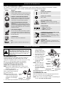 3
3
-
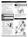 4
4
-
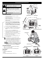 5
5
-
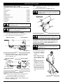 6
6
-
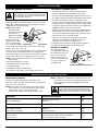 7
7
-
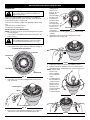 8
8
-
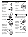 9
9
-
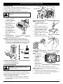 10
10
-
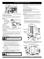 11
11
-
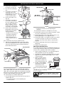 12
12
-
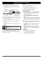 13
13
-
 14
14
-
 15
15
-
 16
16
-
 17
17
-
 18
18
-
 19
19
-
 20
20
-
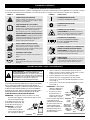 21
21
-
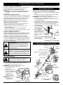 22
22
-
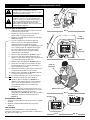 23
23
-
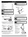 24
24
-
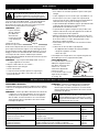 25
25
-
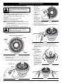 26
26
-
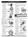 27
27
-
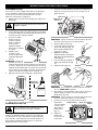 28
28
-
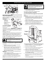 29
29
-
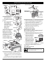 30
30
-
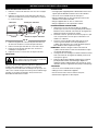 31
31
-
 32
32
-
 33
33
-
 34
34
-
 35
35
-
 36
36
-
 37
37
-
 38
38
-
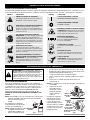 39
39
-
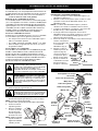 40
40
-
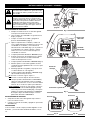 41
41
-
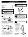 42
42
-
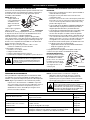 43
43
-
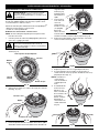 44
44
-
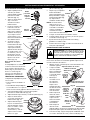 45
45
-
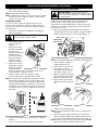 46
46
-
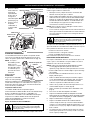 47
47
-
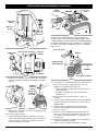 48
48
-
 49
49
-
 50
50
-
 51
51
-
 52
52
-
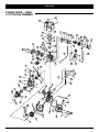 53
53
-
 54
54
-
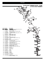 55
55
-
 56
56


Yard Machines Y26SS Manuel utilisateur
- Catégorie
- Coupe-herbe
- Taper
- Manuel utilisateur
dans d''autres langues
- English: Yard Machines Y26SS User manual
- español: Yard Machines Y26SS Manual de usuario