Hatco IHDCH Series Le manuel du propriétaire
- Taper
- Le manuel du propriétaire

P/N 07.04.880.00 © 2019 Hatco Corporation
Intelligent Heated Display Cabinet
Vitrine intelligente
IHDCH Series/Série
Installation and Operating Manual
Manuel d’installation et d’utilisation
Do not operate this equipment unless you
have read and understood the contents
of this manual! Failure to follow the
instructions contained in this manual
may result in serious injury or death.
This manual contains important safety
information concerning the maintenance,
use, and operation of this product. If
you’re unable to understand the contents
of this manual, please bring it to the
attention of your supervisor. Keep this
manual in a safe location for future
reference.
English = p 2
WARNING
No opere este equipo al menos que haya
leído y comprendido el contenido de este
manual! Cualquier falla en el seguimiento
de las instrucciones contenidas en
este manual puede resultar en un serio
lesión o muerte. Este manual contiene
importante información sobre seguridad
concerniente al mantenimiento, uso y
operación de este producto. Si usted
no puede entender el contenido de
este manual por favor pregunte a su
supervisor. Almacenar este manual en
una localización segura para la referencia
futura.
ADVERTENCIA
Ne pas utiliser cet équipement sans avoir
lu et compris le contenu de ce manuel ! Le
non-respect des instructions contenues
dans ce manuel peut entraîner de
graves blessures ou la mort. Ce manuel
contient des informations importantes
concernant l’entretien, l’utilisation et le
fonctionnement de ce produit. Si vous ne
comprenez pas le contenu de ce manuel,
veuillez le signaler à votre supérieur.
Conservez ce manuel dans un endroit
sûr pour pouvoir vous y référer plus tard.
Français = p 14
AVERTISSEMENT
hatcocorp.com
Register Online!
(see page 2)
S’inscrire en ligne !
(voir page 14)

2
Form No. IHDCH45M-0619
English
CONTENTS
Important Owner Information ..............................................2
Introduction ...........................................................................2
Important Safety Information ..............................................3
Model Description ................................................................4
Model Designation ...............................................................4
Specifications .......................................................................5
Plug Configurations .............................................................5
Electrical Rating Chart .........................................................5
Dimensions .......................................................................... 5
Water Supply Specifications ................................................ 5
Installation .............................................................................6
General ................................................................................ 6
Removing the Atomizer Pans .............................................. 7
Installing the Atomizer Pans ................................................ 7
Operation ...............................................................................8
General ................................................................................ 8
Using the Timers .................................................................8
Changing the Cabinet Settings............................................8
Changing the Timer Settings ............................................... 9
Changing Between Celsius and Fahrenheit ........................ 9
Updating the Firmware ........................................................9
Maintenance ........................................................................10
General .............................................................................. 10
Daily Cleaning ...................................................................10
Monthly Cleaning ...............................................................10
Troubleshooting Guide ...................................................... 11
Alert Message Guide ......................................................... 11
Options and Accessories ..................................................12
Limited Warranty ................................................................13
Authorized Parts Distributors ...........................Back Cover
IMPORTANT OWNER INFORMATION
Record the model number, serial number, voltage, and purchase
date of the unit in the spaces below (specification label located
on the back of the unit). Please have this information available
when calling Hatco for service assistance.
Model No. ________________________________________
Serial No. _________________________________________
Voltage ___________________________________________
Date of Purchase ___________________________________
Register your unit!
Completing online warranty registration will prevent delay in
obtaining warranty coverage. Access the Hatco website at
www.hatcocorp.com, select the Support pull-down menu,
and click on “Warranty”.
Business
Hours: 7:00 am to 5:00 pm Monday–Friday,
Central Time (CT)
(Summer Hours: June to September—
7:00 am to 5:00 pm Monday–Thursday
7:00 am to 4:00 pm Friday)
Telephone: 800-558-0607; 414-671-6350
E-mail: [email protected]
24 Hour 7 Day Parts and Service
Assistance available in the United States
and Canada by calling 800-558-0607.
Additional information can be found by visiting our web site at
www.hatcocorp.com.
INTRODUCTION
Hatco Intelligent Heated Display Cabinets are designed to hold
prepared foods for prolonged periods of time while maintaining
that “just-made” quality. Intelligent Heated Display Cabinets
provide the best environment for food products by regulating the
air temperature while at the same time balancing the humidity
level. The use of controlled, moisturized heat maintains serving
temperature and food texture longer than conventional dry
holding equipment.
The air flow pattern is designed to maintain consistent cabinet
temperature without drying out foods. The precise combination
of heat and humidity creates a “blanket” effect around the food.
The air flow rate enables the cabinet to recover temperature
rapidly after opening and closing a door.
Hatco Intelligent Heated Display Cabinets are products of
extensive research and field testing. The materials used were
selected for maximum durability, attractive appearance, and
optimum performance. Every unit is inspected and tested
thoroughly prior to shipment.
This manual provides the installation, safety, and operating
instructions for Intelligent Heated Display Cabinets. Hatco
recommends all installation, operating, and safety instructions
appearing in this manual be read prior to installation or operation
of a unit.
Safety information that appears in this manual is identified by
the following signal word panels:
WARNING
WARNING indicates a hazardous situation which, if not
avoided, could result in death or serious injury.
CAUTION
CAUTION indicates a hazardous situation which, if not
avoided, could result in minor or moderate injury.
NOTICE
NOTICE is used to address practices not related to personal
injury.

3
Form No. IHDCH45M-0619
English
IMPORTANT SAFETY INFORMATION
WARNING
Make sure all operators have been instructed on the safe
and proper use of the unit.
This unit is not intended for use by children or persons
with reduced physical, sensory, or mental capabilities.
Ensure proper supervision of children and keep them away
from the unit.
This unit has no “user-serviceable” parts. If service
is required on this unit, contact an Authorized Hatco
Service Agent or contact the Hatco Service Department at
800-558-0607 or 414-671-6350.
CAUTION
BURN HAZARD:
• Some exterior surfaces on the unit will get hot. Use
caution when touching these areas.
• Do not remove or adjust atomizer pans when unit is
hot. Allow unit to cool completely before working with
atomizer pans.
Locate unit at proper counter height in an area that is
convenient for use. Location should be level to prevent
unit or its contents from falling accidentally and strong
enough to support the weight of the unit and contents.
The National Sanitation Foundation (NSF) requires that
units over 36″ (914 mm) in width or weighing more than
80 lbs. (36 kg) either be sealed to or raised above the
installation surface.
Do not move or relocate the unit for cleaning. The unit is
bulky and heavy.
Transport unit in upright position only. Before moving
unit, secure all glass surfaces, doors, and support arms
with tape. Failure to do so may result in damage to unit or
personal injury.
NOTICE
Do not locate unit in area with excessive air movement
around unit. Avoid areas that may be subject to active air
movements or currents (i.e., near exhaust fans/hoods, air
conditioning ducts, and exterior doors).
Use non-abrasive cleaners and cloths only. Abrasive
cleaners and cloths could scratch finish of unit, marring its
appearance and making it susceptible to soil accumulation.
IMPORTANT—DO NOT use paper towel or glass cleaner to
clean plastic surfaces such as sliding doors. Paper towel
and glass cleaner may scratch the material. Wipe off plastic
surfaces using a soft, clean, water-dampened cloth.
Use detachable hose sets supplied with unit. Do not use
old hose sets.
Clean unit daily to avoid malfunctions and maintain
sanitary operation.
WARNING
ELECTRIC SHOCK HAZARD:
• Plug unit into a properly grounded electrical receptacle
of the correct voltage, size, and plug configuration. If
plug and receptacle do not match, contact a qualified
electrician to determine and install proper voltage and
size electrical receptacle.
• Turn OFF power switch, unplug power cord, and
allow unit to cool before performing any cleaning,
adjustments, or maintenance.
• DO NOT submerge or saturate with water. Unit is not
waterproof. Do not operate if unit has been submerged
or saturated with water.
• Unit is not weatherproof. Locate unit indoors where
ambient air temperature is a minimum of 70°F (21°C).
• This unit is not “jet-proof” construction. Do not use jet-
clean spray to clean this unit.
• Do not steam clean or use excessive water on unit.
• Do not pull unit by power cord.
• Discontinue use if power cord is frayed or worn.
• Do not attempt to repair or replace a damaged power
cord. Cord must be replaced by Hatco, an Authorized
Hatco Service Agent, or a person with similar
qualifications.
• This unit must be serviced by qualified personnel only.
Service by unqualified personnel may lead to electric
shock or burn.
• Use only Genuine Hatco Replacement Parts when
service is required. Failure to use Genuine Hatco
Replacement Parts will void all warranties and may
subject operators of the equipment to hazardous
electrical voltage, resulting in electrical shock or burn.
Genuine Hatco Replacement Parts are specified to
operate safely in the environments in which they are
used. Some aftermarket or generic replacement parts
do not have the characteristics that will allow them to
operate safely in Hatco equipment.
FIRE HAZARD:
• Install unit on non-combustible surface only.
• Locate unit a minimum of 1″ (25 mm) from combustible
walls and materials. If safe distances are not maintained,
discoloration or combustion could occur.
• Do not place anything on top of unit.
Make sure food product has been heated to the proper
food-safe temperature before placing in unit. Failure to
heat food product properly may result in serious health
risks. This unit is for holding pre-heated food product only.
Hatco Corporation is not responsible for actual food
product serving temperature. It is the responsibility of the
user to ensure that food product is held and served at a
safe temperature.
The light fixtures in this unit have safety shields covering
the light bulbs to meet National Sanitation Foundation
(NSF) standards. To avoid personal injury and/or food
contamination, always operate the unit with the safety
shields properly installed.
Read the following important safety information before using this equipment to avoid serious
injury or death and to avoid damage to equipment or property.

4
Form No. IHDCH45M-0619
English
MODEL DESCRIPTION
Model IHDCH-45
IHDCH-45 models can be configured with up to six adjustable
product support arms. The product support arms are capable of
holding a maximum pizza size of 19-1/2″. Access to the cabinet
is through rear sliding doors.
Power I/O
(on/off) Switch
Cooling
Fan Inlet
Sliding
Doors
USB
Port
Water
Inlet
Fitting
Overflow
Drain Pipe
Cooling Fan
Outlet
Touchscreen
Controller
Adjustable Product
Support Arm
Base
Pieces
Front and Rear view of Model IHDCH-45
All Models
All Hatco Intelligent Heated Display Cabinets are constructed
of stainless steel and aluminum with tempered glass top,
front, side, and door panels. Units are available with a black,
powdercoated finish or in stainless steel.
All models feature a touchscreen controller, a lighted Power
I/O (on/off) switch, an air heating/circulation system, a humidity
system, a USB port, and LED display lights. The inside of the
cabinet features removable base pieces as well as removable
front and rear crumb trays. Units are equipped with a 6ʹ
(1829 mm) power cord with plug.
NOTE: A water filter assembly is included with the unit to install
on the water supply line before it enters the unit.
NOTE: Refer to the OPTIONS AND ACCESSORIES section for
details on available accessories and factory-installed
options.
Model IHDCH-28
IHDCH-28 models can be configured with up to three adjustable
product support arms or up to three movable shelves. The
product support arms and shelves are capable of holding a
maximum pizza size of 22″. Access to the cabinet is through
a rear, hinged door—which can be installed as either right or
left-hinged.
Power I/O
(on/off)
Switch
Cooling
Fan Inlet
Door
USB
Port
Water
Inlet
Fitting
Overflow
Drain Pipe
Touchscreen
Controller
Adjustable
Product
Support Arm
Base
Pieces
Rear view of Model IHDCH-28
MODEL DESIGNATION
I H D C H - xx
Intelligent
Heated Display Cabinet
Humidified
Width (inches)

5
Form No. IHDCH45M-0619
English
Model
Width
(A)
Depth
(B)
Height
(C)
Base
Width (D)
Base
Depth (E)
Support Arm
Diameter (F)
Riser
Diameter (G)*
IHDCH-28
28-1/4″
(718 mm)
28-11/16″
(728 mm)
30-3/16″
(766 mm)
28″
(711 mm)
27″
(686 mm)
13-1/2 to 22″
(343 to 559 mm)
12″
(305 mm)
IHDCH-45
45-1/4″
(1149 mm)
28-3/8″
(721 mm)
30-3/16″
(766 mm)
45″
(1143 mm)
27″
(686 mm)
12 to 19-1/2″
(305 to 495 mm)
12″
(305 mm)
Heated Chamber Dimensions: IHDCH-28 = 27-1/8″ W x 25-1/2″ D x 22-5/8″ H (689 x 648 x 574 mm)
IHDCH-45 = 44-1/8″ W x 25-1/2″ D x 22-5/8″ H (1121 x 648 x 574 mm)
Food Product Riser Height = 1-1/4″ (32 mm) *
Model Voltage Watts Amps Plug Configuration Shipping Weight
IHDCH-28 208
3090
14.9
NEMA 6-20P 150 lbs. (68 kg)
240 12.9
IHDCH-45 208
3090
14.9
NEMA 6-20P 200 lbs. (91 kg)
240 12.9
SPECIFICATIONS
Plug Configurations
Units are supplied from the factory with an electrical cord and
plug installed (plugs are supplied according to the application).
WARNING
ELECTRIC SHOCK HAZARD: Plug unit into a properly
grounded electrical receptacle of the correct voltage,
size, and plug configuration. If plug and receptacle do not
match, contact a qualified electrician to determine and
install proper voltage and size electrical receptacle.
NOTE: Specification label located on the back of the unit. See
label for serial number and verification of unit electrical
information.
NEMA 6-20P
Plug Configurations
NOTE: Receptacle not supplied by Hatco.
Electrical Rating Chart
Dimensions
A
B
E
F
3-1/2"
(88 mm)
3-3/4"
(95 mm)
4"
(102 mm)
G
D
C
Front View
Side View
IHDCH-45 shown
* Available as an accessory.
Water Supply Specifications
Water Pressure = 20 psi (138 kPa) minimum, 50 psi (345 kPa) maximum

6
Form No. IHDCH45M-0619
English
INSTALLATION
General
Hatco Intelligent Heated Display Cabinets are shipped with
most components installed and ready for operation. Care
should be taken when unpacking shipping carton to avoid
damage to unit and the components enclosed. The following
installation instructions must be performed before connecting
electricity and operating the cabinet.
WARNING
ELECTRIC SHOCK HAZARD: Unit is not weatherproof.
Locate unit indoors where ambient air temperature is a
minimum of 70°F (21°C).
FIRE HAZARD:
• Locate unit a minimum of 1″ (25 mm) from combustible
walls and materials. If safe distances are not maintained,
discoloration or combustion could occur.
• Do not place anything on top of unit.
CAUTION
Locate unit at proper counter height in an area that is
convenient for use. Location should be level to prevent
unit or its contents from falling accidentally and strong
enough to support the weight of the unit and contents.
The National Sanitation Foundation (NSF) requires that
units over 36″ (914 mm) in width or weighing more than
80 lbs. (36 kg) either be sealed to or raised above the
installation surface.
1. Remove the unit from the shipping carton.
2. Remove tape and protective film from all surfaces of unit.
NOTE: To prevent delay in obtaining warranty coverage,
complete online warranty registration. See the
IMPORTANT OWNER INFORMATION section for
details.
3. Place the unit in the desired location. Two or more people
are required for this procedure.
• Locate the unit in an area where the ambient air
temperature is constant and a minimum of 70°F
(21°C). Avoid areas that may be subject to active air
movements or currents (i.e., near exhaust fans/hoods,
air conditioning ducts, and exterior doors/openings).
• Make sure the unit is at the proper counter height in an
area convenient for use.
• Make sure the countertop is level and strong enough to
support the weight of the unit and food product.
4. Seal the unit to the countertop using an NSF-approved
sealant.
NOTE: A shut-off valve must be installed on the water supply
line immediately upstream from the water filter and unit.
NOTE: Incoming water pressure for the unit must be between
20 psi (138 kPa) and 50 psi (345 kPa). If incoming
pressure is too high, a pressure regulator must be
installed upstream from the water filter. See OPTIONS
AND ACCESSORIES for details.
5. Connect the on-site water supply from the shut-off valve to
the included water filter.
NOTE: Make sure to note the flow direction arrow on the water
filter, which should be pointing toward the unit.
6. Flush the water filter to remove loose carbon particles.
Residual particles from a new filter can affect the humidity
system.
a. Connect the included 1/4″ clear tubing to the water outlet
on the filter, and place the opposite end of the tube into
a waste container.
b. Turn on the water supply and flush the filter into the
container until the water is clear of carbon particles.
7. Connect the 1/4″ clear tubing from the water outlet on the
filter to either fitting on the included water strainer.
• The fittings on the water strainer are “push-in”-style
connections for 1/4″ plastic tubing.
8. Connect the water strainer to the 1/4″ water inlet fitting on
the back of the unit.
• The water inlet fitting is a “push-in”-style connection for
1/4″ plastic tubing.
9. Provide a catch pan for the overflow drain pipe on the back
of the unit.
• The 3/8″ overflow drain pipe also can be connected to an
on-site drain line. Consult a licensed plumber for proper
drain installation that conforms to local codes.
NOTE: Water will drain only if a problem occurs with the water
supply connection. During normal operation, all water
will be atomized into the cabinet by the humidity system.
Water Inlet
Fitting
Water Supply
Tube
Overflow Drain
Pipe
Connecting the Water Supply (IHDCH-45 shown)
CAUTION
BURN HAZARD: Do not remove or adjust atomizer pans
when unit is hot. Allow unit to cool completely before
working with atomizer pans.
10. Verify that each atomizer pan is in the proper position.
NOTE: The humidity system includes two atomizer pans, one
on each side of the unit underneath the vent cover at the
front of the unit. These pans are loose and may have
moved out of position during shipping and installation.
a. Remove the vent cover located along the bottom, front of
the unit by reaching in through the rear sliding doors.
b. Inspect the position of the atomizer pans on each side of
the unit.
• The handle of the atomizer pan should be aligned
vertically with the top edge of the opening.
c. If the handle is pushed into the unit too far:
• Remove the atomizer pan, reposition on top of the pan
supports, and push the pan toward the back of the unit
on the pan supports until it stops against the backstop.

7
Form No. IHDCH45M-0619
English
INSTALLATION
d. If the handle extends out into the opening:
• Push the atomizer pan toward the back of the unit until
it stops against the backstop.
Atomizer
Pans
Front glass and product
support arms removed
for clarity.
Front
Vent Cover
(removed through
sliding door)
Pan Handle
aligned with
top edge of
opening.
Top edge
of opening
Checking the Atomizer Pans (IHDCH-45 shown)
Atomizer Pan
Pan Support
Heating Element
Front glass removed
for clarity.
Atomizer Pan Location (IHDCH-45 shown)
11. Turn on the water supply and check for leaks.
12. Install the product support arms or shelves in the desired
positions.
To install a product support arm:
a. Align the hooks on the end of the arm with the desired
slots on the support bracket.
b. Insert the hooks into the slots, and lower the support arm
until it stops.
To install a shelf:
a. Align the hooks on each side of the shelf with the desired
slots on the support brackets.
b. Insert the hooks into the slots, and lower the shelf until it
stops.
13. Plug the unit into a properly grounded electrical receptacle
of the correct voltage, size, and plug configuration. See the
SPECIFICATIONS section for details.
Removing the Atomizer Pans
Use the following procedure to remove the two atomizer pans
located underneath the vent cover at the front of the unit.
1. Make sure the Power I/O (on/off) switch is in the O (off)
position, the power cord is unplugged, and the unit is cool.
2. Remove the vent cover located along the bottom, front of
the unit by reaching in through the rear sliding doors.
3. Locate the atomizer pans inside the opening at the front of
the unit, one on each side.
• The atomizer pans sit on pan supports directly above a
heating element.
4. Remove the atomizer pans. To remove a pan:
a. Reach inside the front opening and grab the pan handle.
b. Start pulling the pan toward the front of the unit while
angling the pan up.
c. Continue to lift and angle the pan up until it is clear of the
front opening.
Front Opening
Atomizer Pan
Removing/Installing the Atomizer Pans (IHDCH-45 shown)
Installing the Atomizer Pans
Use the following procedure to install the atomizer pans.
1. Make sure the Power I/O (on/off) switch is in the O (off)
position, the power cord is unplugged, and the unit is cool.
2. If it is present, remove the vent cover located along the
bottom, front of the unit by reaching in through the rear
sliding doors.
3. Install the atomizer pans. To install a pan:
a. Hold the pan by the handle and at an angle above the
front opening.
b. Lower the pan into the opening and set the front edge of
the pan onto the pan supports located directly above the
heating element.
c. Push the pan toward the back of the unit on the pan
supports until it stops against the backstop.
NOTE: If the atomizer pan does not stop, it was installed
improperly. Repeat step 3 of this procedure.
d. Make sure the handle of the atomizer pan is aligned
vertically with the top edge of the opening.

8
Form No. IHDCH45M-0619
English
General
Use the following procedures to operate a Hatco Intelligent
Heated Display Cabinet.
WARNING
Read all safety messages in the IMPORTANT SAFETY
INFORMATION section before operating this equipment.
Make sure food product has been heated to the proper
food-safe temperature before placing in unit. Failure to
heat food product properly may result in serious health
risks. This unit is for holding pre-heated food product only.
CAUTION
BURN HAZARD: Some exterior surfaces on the unit will get
hot. Use caution when touching these areas.
Startup
1. Verify that the unit is plugged into a properly grounded
electrical receptacle of the correct voltage, size and plug
configuration. See the SPECIFICATIONS section for
details.
2. Verify that the atomizer pans are installed correctly (see
INSTALLATION section for details). NOTICE: Never
operate unit without atomizer pans in proper position.
3. Verify that the unit is connected to the on-site water supply
(see INSTALLATION section for details).
Power I/O
(on/off) Switch
Sliding
Door
Touchscreen
Controller
Controls (IHDCH-45 shown)
4. Move the Power I/O (on/off) switch to the I (on) position.
0:40:00 0:40:00
0:40:00 0:40:00
0:40:00 0:40:00
0:40:00 0:40:00
• The display lights will turn
on, the heating and humidity
systems will start up.
• The touchscreen controller
will energize and show the
Home Screen. The Home
Screen shows the available
timers that correspond with
each product position inside
the cabinet.
NOTE: The and keys will appear in red during
preheating. Once the cabinet reaches the operating
setpoints, the keys will change to green.
5. Allow the unit 60 minutes to reach operating temperature
and humidity setting before loading the cabinet with pre-
heated food product.
NOTE: The cabinet can hold pizzas with a maximum diameter
of 18″ (457 mm).
180˚ 17%
• Touch the key to show
the current air temperature
and relative humidity (RH)
inside the cabinet. Touch
the key to return to the
timers on the Home Screen.
NOTE: The cabinet is pre-set
at the factory to an air
temperature of 180°F (82°C) and 17% relative humidity.
6. Refer to the “Adjusting the Settings” procedure in this
section to change the air temperature and relative humidity
(RH) settings, if necessary.
Shutdown
1. Move the Power I/O (on/off) Switch to the O (off) position
and allow the unit to cool completely.
2. Perform the “Daily Cleaning” procedure in the
MAINTENANCE section of this manual.
Using the Timers
Use the following procedure to use timers for the product in the
cabinet.
1. Make sure the Home Screen with the available timers is
shown on the display. If not, touch the key.
NOTE: The position of the timers on the screen corresponds
with the position of the product in the cabinet, when
viewing from the operator side.
0:35:43 0:21:15
0:39:55 0:05:05
0:00:00 0:40:00
Timer at zero
highlighted in red.
2. Start the desired timer(s).
• Touch a timer to start a
countdown from the pre-set
time setting.
• Touch and hold a timer for
three seconds to turn off and
reset the timer.
• When a timer has one
minute remaining, it will be
highlighted in flashing red.
When a timer reaches zero, the red highlight on the timer
will remain solid until it is reset by the operator.
Changing the Cabinet Settings
Use the following procedure to set or change the air temperature
and humidity settings of the cabinet. The cabinet is pre-set at
the factory to an air temperature of 180°F (82°C) and 17%
relative humidity.
1. Move the Power I/O (on/off) switch to the I (on) position.
• The unit will turn on and the touchscreen controller will
energize and show the Home Screen.
OPERATION

9
Form No. IHDCH45M-0619
English
OPERATION
Service
Firmware Usage
Control Timers
Testmode TempHumid
2. Touch the key.
• Enter the password "248"
using the number keys that
appear.
• The Service screen will
appear on the display.
3. Touch the TEMPHUMID key
on the Service screen to
access the air temperature and relative humidity settings.
4. Adjust the air temperature and/or relative humidity settings.
180˚ 17%
• Touch the red or
key on the left side of the
display to set the desired
air temperature.
• Touch the blue or
key on the right side of the
display to set the desired
relative humidity (RH).
NOTE: Air temperature and humidity settings may vary
depending upon product make-up and consistency.
5. Touch the key to save the settings and return to the
Home Screen.
Changing the Timer Settings
Use the following procedure to change the time setting on each
of the product timers.
1. Move the Power I/O (on/off) switch to the I (on) position.
• The unit will turn on and the touchscreen controller will
energize and show the Home Screen.
2. Touch the key.
• Enter the password "248" using the number keys that
appear.
• The Service screen will appear on the display.
3. Touch the TIMERS key on the Service screen to access
the Timers screen.
Timers
Select Config
(Max 8 timers)
MaxSetting
NOTE: The check boxes on the
Timers screen correspond
with each available product
timer, when viewing unit
from the operator side.
Touch the appropriate check
box to toggle the timer
between visible and invisible
on the Home screen.
4. Touch the MAXSETTING key on the Timers screen to
access the timer settings.
0:40 0:40
0:40 0:40
0:40 0:40
Set
a. Touch the SET key to
highlight the first timer
setting.
b. Touch the red or key
on the display to change the
timer setting.
c. Touch the next desired timer
setting to make it active for
change, and repeat the previous step to change the setting.
d. Touch the DONE key when timer setting changes are
complete.
5. Touch the key to save the settings and return to the
Home Screen.
Changing Between Celsius and Fahrenheit
Use the following procedure to change the air temperature unit
of measure between Celsius and Fahrenheit.
1. Move the Power I/O (on/off) switch to the I (on) position.
• The unit will turn on and the touchscreen controller will
energize and show the Home Screen.
Service
Firmware Usage
Control Timers
Testmode TempHumid
2. Touch the key.
• Enter the password "248"
using the number keys that
appear.
• The Service screen will
appear on the display.
3. Touch the CONTROL key on
the Service screen to access
the Control Settings screen.
4. Choose the desired unit of measure on the “Units” line:
Control Settings
SWHHID45PH0201
Units F C
Version 01.00.27
• Touch the ”F” box to select
Fahrenheit.
• Touch the ”C” box to select
Celsius.
NOTE: The box for the active unit
of measure is highlighted in
green.
5. Touch the key to save the settings and return to the
Home Screen.
Updating the Firmware
Use the following procedure to perform a firmware update on
the touchscreen controller.
1. Move the Power I/O (on/off) switch to the I (on) position.
• The unit will turn on and the touchscreen controller will
energize and show the Home Screen.
2. Touch the key.
• Enter the password "248" using the number keys that
appear.
• The Service screen will appear on the display.
3. Touch the FIRMWARE key on the Service screen to access
the Firmware Update screen.
Firmware Update
Plug-in the USB stick, then
press the Update button.
Update
4. Insert the USB drive into the
USB port next to the controller,
and touch the UPDATE key on
the Firmware Update screen.
• The update will begin. When
complete, the touchscreen
controller will restart and
show the Home screen.

10
Form No. IHDCH45M-0619
English
MAINTENANCE
General
Hatco Intelligent Heated Display Cabinets are designed for
maximum durability and performance, with minimum maintenance.
WARNING
ELECTRIC SHOCK HAZARD:
• Turn OFF power switch, unplug power cord, and
allow unit to cool before performing any cleaning,
adjustments, or maintenance.
• DO NOT submerge or saturate with water. Unit is not
waterproof. Do not operate if unit has been submerged
or saturated with water.
• This unit is not “jet-proof” construction. Do not use jet-
clean spray to clean this unit.
• Do not steam clean or use excessive water on unit.
• Use only Genuine Hatco Replacement Parts when
service is required. Failure to use Genuine Hatco
Replacement Parts will void all warranties and may
subject operators of the equipment to hazardous
electrical voltage, resulting in electrical shock or burn.
Genuine Hatco Replacement Parts are specified to
operate safely in the environments in which they are
used. Some aftermarket or generic replacement parts
do not have the characteristics that will allow them to
operate safely in Hatco equipment.
This unit has no “user-serviceable” parts. If service
is required on this unit, contact an Authorized Hatco
Service Agent or contact the Hatco Service Department at
800-558-0607 or 414-671-6350.
Daily Cleaning
To maintain performance and preserve the finish of the cabinet,
it is recommended that the unit be cleaned daily.
NOTICE
Use non-abrasive cleaners and cloths only. Abrasive
cleaners and cloths could scratch finish of unit, marring its
appearance and making it susceptible to soil accumulation.
1. Move the Power I/O (on/off) switch to the O (off) position
and unplug the power cord. Allow the unit to cool.
2. Remove and clean all internal components.
• Components include risers, product supports arms,
shelves, front and rear vent covers, crumb trays (located
directly below the front and rear vent covers), and the
decorative base pieces.
• Clean and sanitize the components in a 3-compartment
sink, and allow to air dry.
NOTE: The above listed components are dishmachine-safe.
Not all dishmachine detergents have been tested. If a
noticeable change in color or gloss occurs, an alternate
detergent should be used.
3. Wipe down all interior and exterior metal surfaces using a
clean, damp, non-abrasive cloth. A non-abrasive cleaner
may be used for difficult stains. Hard to reach areas should
be cleaned using a small brush and mild soap.
4. Clean all glass panels and glass doors using a standard
glass cleaner.
5. Clean polycarbonate sliding doors using soft, microfiber
cleaning cloths, mild soap, and water. NOTICE: Do not
use paper towel or glass cleaner on plastic surfaces—
scratching or damage may occur.
6. Spray all interior and exterior surfaces with sanitizing
solution and allow to air dray.
7. Reassemble the unit.
Front glass removed for clarity.
All components removed
through rear sliding door.
Front Vent
Cover
Base
Pieces
Front Crumb Tray
(under vent cover)
Rear
Crumb
Tray
Rear Vent Cover
Removing/Installing Components (IHDCH-45 shown)
Monthly Cleaning
Use the following procedure for periodic cleaning and deliming
of the atomizer pans.
NOTE: The lime and mineral content of the water used for
daily operation will determine how often the deliming
procedure must be performed.
NOTE: Perform this procedure when the unit will not be used
for a period of time, such as the end of the day.
1. Move the Power I/O (on/off) switch to the O (off) position and
unplug the power cord. Allow the unit to cool completely.
2. Perform steps 2–5 of the “Daily Cleaning” procedure.
3. Remove both atomizer pans (refer to the “Removing the
Atomizer Pans” procedure in the INSTALLATION section
of this manual).
4. Fill an appropriate container with a mixture of 75% water
and 25% white vinegar. Do not use flavored vinegar.
5. Place both atomizer pans into the vinegar solution and
allow to soak for several hours, preferably overnight.
6. Remove both atomizer pans from the vinegar solution and
clean using warm, soapy water and a soft cloth.
7. Rinse both atomizer pans with clean water, and allow to air
dry.
8. Install the cleaned atomizer pans into the unit (refer
to the “Installing the Atomizer Pans” procedure in the
INSTALLATION section of this manual).
9. Spray all interior and exterior surfaces with sanitizing
solution and allow to air dry.
10. Reassemble the unit.

11
Form No. IHDCH45M-0619
English
Symptom Probable Cause Corrective Action
Unit operates, but is not circulating air
inside cabinet.
Blower motor(s) defective.
Contact Authorized Service Agent or Hatco for assistance.
The correct voltage may not be supplied
to blowers.
Unit is plugged in, but nothing works. No power to unit. Check electrical receptacle and verify that power supply
matches specifications on unit. If receptacle is not working,
check circuit breaker and reset, or plug unit into a different
known working receptacle.
Power cord connections are loose or
disconnected.
Contact Authorized Service Agent or Hatco for assistance.
Power cord is damaged.
Defective Power I/O (on/off) switch.
Unit is not producing any “hot air”
inside cabinet.
Safety high-limit is tripped or open.
Contact Authorized Service Agent or Hatco for assistance..
Incorrect voltage supplied to heating element.
Blower motor(s) not working.
Air heating element(s) defective.
Unit is heating, but is not producing
humidity inside cabinet.
Unit has not been operating for at least
30 minutes.
Allow at least 30 minutes after unit is turned on for humidity
cycle to start. Then, allow another 30 minutes to reach
humidity setting. Every time power is turned off, unit requires
30 minutes after it is turned on for humidity cycle to start.
Humidity setting too low. Increase the humidity setting (see OPERATION section).
Water supply is off or not connected. Make sure unit is connected to water supply and the shut-
off valve is open.
Incorrect voltage supplied to water heating
elements or heating elements defective.
Contact Authorized Service Agent or Hatco for assistance.
Alert Message Guide
Touch SNOOZE to postpone an Alert Message for five minutes and return to operation. Touch DISABLE to reset an Alert Message. Always
investigate and correct the causes of an Alert Message.
TROUBLESHOOTING GUIDE
WARNING
This unit must be serviced by trained and qualified personnel
only. Service by unqualified personnel may lead to electric shock
or burn.
WARNING
ELECTRIC SHOCK HAZARD: Turn OFF power switch, unplug
power cord, and allow unit to cool before performing any cleaning,
adjustments, or maintenance.
Alert Message Troubleshooting
Corrective Action
(if Troubleshooting fails to fix)
Error
SNOOZE DISABLE
Low Cabinet Temp
Make sure doors are closed. Contact Authorized Service Agent or Hatco for
assistance.
Error
SNOOZE DISABLE
Low Cabinet Humidity
Make sure water supply is connected and
turned on. Allow 60 minutes for cabinet to
reach humidity setting.
Contact Authorized Service Agent or Hatco for
assistance.
Error
SNOOZE DISABLE
Bad Probe Connection
Defective temperature probe. Contact Authorized Service Agent or Hatco for
assistance.
Error
SNOOZE DISABLE
PCB Temp Too High
Make sure inlet and outlet openings for the
cooling fan are not blocked and air flow is not
restricted. Restart cabinet.
Contact Authorized Service Agent or Hatco for
assistance.

12
Form No. IHDCH45M-0619
English
TROUBLESHOOTING GUIDE
Troubleshooting Questions?
If you continue to have problems resolving an issue, please contact the nearest Authorized Hatco Service Agency or Hatco for
assistance. To locate the nearest Service Agency, log onto the Hatco website at www.hatcocorp.com, select the Support pull-
down menu, and click on “Find A Service Agent”; or contact the Hatco Parts and Service Team at:
Telephone: 800-558-0607 or 414-671-6350
e-mail: [email protected]
OPTIONS AND ACCESSORIES
Sign Holders
Three different sign holders are available as accessories: floor
sign holder, left pan sign holder, and right pan sign holder. The
floor sign holder rests on the base pieces inside the cabinet.
The left pan sign holder and right pan sign holder are installed
on the product support arms.
Floor
Sign Holder
Left Pan
Sign Holder
Right Pan
Sign Holder
Food Product Riser
A circular food product riser is available as
an accessory with a black, powdercoated
finish or in stainless steel. Food product
risers sit directly on the base pieces inside
the cabinet to allow additional food display
options. One riser will fit in IHDCH-28 models, and two risers
will fit in IHDCH-45 models.
Water Pressure Regulator Kit
A water pressure regulator kit is available as an accessory. A
water pressure regulator is required when the incoming water
pressure is greater than 50 psi (345 kPa). The water pressure
regulator kit includes a pressure regulator, pressure gauge, and
shutoff valve.
Front Door Kit
A hinged, self-closing front door kit is available for IHDCH-28
models as an accessory. Installing a front door converts the unit
to a pass-through style cabinet, and allows customer access to
the food product.
Glass Cleaning Kit
A glass cleaning kit is available as an accessory. The glass
cleaning kit consists of a cleaning base, removable extension
pole, and re-usable/washable microfiber pads. The microfiber
pads attach to the cleaning base to provide lint-free cleaning of
glass surfaces.
Reverse Osmosis System
A reverse osmosis (RO) system is available as an accessory.
The RO system is installed upstream from the unit in the water
supply line. RO water will decrease the amount of lime and
mineral deposits in the humidification system, extending the
time between necessary cleanings.

13
Form No. IHDCH45M-0619
English
1. PRODUCT WARRANTY
Hatco warrants the products that it manufactures (the “Products”)
to be free from defects in materials and workmanship, under
normal use and service, for a period of one (1) year from the
date of purchase when installed and maintained in accordance
with Hatco’s written instructions or 18 months from the date
of shipment from Hatco. Buyer must establish the Product’s
purchase date by registering the Product with Hatco or by other
means satisfactory to Hatco in its sole discretion.
Hatco warrants the following Product components to be free
from defects in materials and workmanship from the date of
purchase (subject to the foregoing conditions) for the period(s)
of time and on the conditions listed below:
a) One (1) Year Parts and Labor PLUS One (1) Additional
Year Parts-Only Warranty:
Conveyor Toaster Elements (metal sheathed)
Drawer Warmer Elements (metal sheathed)
Drawer Warmer Drawer Rollers and Slides
Strip Heater Elements (metal sheathed)
Display Warmer Elements (metal sheathed air heating)
Holding Cabinet Elements (metal sheathed air heating)
Heated Well Elements — HW and HWB Series
(metal sheathed)
b) Two (2) Year Parts and Labor Warranty:
Induction Ranges
Induction Warmers
c) One (1) Year Parts and Labor PLUS Four (4) Years
Parts-Only Warranty:
3CS and FR Tanks
d) One (1) Year Parts and Labor PLUS Nine (9) Years
Parts-Only Warranty on:
Electric Booster Heater Tanks
Gas Booster Heater Tanks
e) Ninety (90) Day Parts-Only Warranty:
Replacement Parts
THE FOREGOING WARRANTIES ARE EXCLUSIVE AND
IN LIEU OF ANY OTHER WARRANTY, EXPRESSED OR
IMPLIED, INCLUDING BUT NOT LIMITED TO ANY IMPLIED
WARRANTY OF MERCHANTABILITY OR FITNESS FOR
A PARTICULAR PURPOSE OR PATENT OR OTHER
INTELLECTUAL PROPERTY RIGHT INFRINGEMENT. Without
limiting the generality of the foregoing, SUCH WARRANTIES
DO NOT COVER: Coated incandescent light bulbs, fluorescent
lights, heat lamp bulbs, coated halogen light bulbs, halogen
heat lamp bulbs, xenon light bulbs, LED light tubes, glass
components, and fuses; Product failure in booster tank, fin tube
heat exchanger, or other water heating equipment caused by
liming, sediment buildup, chemical attack, or freezing; or Product
misuse, tampering or misapplication, improper installation, or
application of improper voltage.
2. LIMITATION OF REMEDIES AND DAMAGES
Hatco’s liability and Buyer’s exclusive remedy hereunder will
be limited solely, at Hatco’s option, to repair or replacement
using new or refurbished parts or Product by Hatco or a Hatco-
authorized service agency (other than where Buyer is located
outside of the United States, Canada, United Kingdom, or
Australia, in which case Hatco’s liability and Buyer’s exclusive
remedy hereunder will be limited solely to replacement of part
under warranty) with respect to any claim made within the
applicable warranty period referred to above. Hatco reserves
the right to accept or reject any such claim in whole or in part. In
the context of this Limited Warranty, “refurbished” means a part
or Product that has been returned to its original specifications
by Hatco or a Hatco-authorized service agency. Hatco will not
accept the return of any Product without prior written approval
from Hatco, and all such approved returns shall be made at
Buyer’s sole expense. HATCO WILL NOT BE LIABLE, UNDER
ANY CIRCUMSTANCES, FOR CONSEQUENTIAL OR
INCIDENTAL DAMAGES, INCLUDING BUT NOT LIMITED TO
LABOR COSTS OR LOST PROFITS RESULTING FROM THE
USE OF OR INABILITY TO USE THE PRODUCTS OR FROM
THE PRODUCTS BEING INCORPORATED IN OR BECOMING
A COMPONENT OF ANY OTHER PRODUCT OR GOODS.
LIMITED WARRANTY

14
Formulaire n° IHDCH45M-0619
Français
SOMMAIRE
Informations Importantes pour le Propriétaire ................14
Introduction .........................................................................14
Consignes de Sécurité Importantes ................................. 15
Description du Modèle .......................................................16
Désignation du Modèle ...................................................... 17
Caractéristiques Techniques ............................................17
Configuration des fiches .................................................... 17
Tableau des valeurs nominales électriques ......................17
Dimensions ........................................................................ 17
Caractéristiques de l’approvisionnement en eau ..............17
Installation ...........................................................................18
Généralités ........................................................................18
Retrait des plateaux atomiseurs ........................................19
Installation des plateaux atomiseurs .................................19
Mode d’emploi ....................................................................20
Généralités ........................................................................20
Utilisation des minuteurs ...................................................21
Modifier les réglages de la vitrine ......................................21
Modifier les réglages du minuteurs ...................................21
Basculement entre Celsius et Fahrenheit .........................22
Mise à jour du logiciel ........................................................22
Maintenance ........................................................................23
Généralités ........................................................................23
Nettoyage quotidien ...........................................................23
Nettoyage mensuel ............................................................23
Guide de Dépannage ..........................................................24
Guide des messages d’alerte ............................................25
Options et accessoires ...................................................... 26
Garantie Limitée .................................................................27
Distributeurs de pièces autorisés ........Couverture Arrière
INFORMATIONS IMPORTANTES POUR LE PROPRIÉTAIRE
Notez le numéro de modèle, le numéro de série, la tension et la
date d’achat de l’appareil dans les espaces ci-dessous (étiquette
de spécification située sur le côté de l’appareil). Veuillez avoir
cette information à portée de la main si vous appelez Hatco pour
assistance.
Modèle No. ______________________________________
Numéro de série __________________________________
Voltage _________________________________________
Date d’achat _____________________________________
Enregistrez votre appareil!
Remplissez la garantie en ligne pour éviter les retards
pour faire jouer la garantie. Accédez au site Web Hatco
www.hatcocorp.com, sélectionnez le menu déroulant
Support (Assistance), puis cliquez sur « Warranty » (Garantie).
Horaires
ouvrables : 7h00 à 17h00 du lundi au vendredi
Heure du Centre (CT)
(Horaires d’été : juin à septembre—
7h00 à 17h00 du lundi au jeudi
7h00 à 16h00 le vendredi)
Téléphone: 800-558-0607; 414-671-6350
Courriel: [email protected]
Service d'assistance et de pièces de
rechange disponible 7j/7, 24h/24 aux
États-Unis et au Canada en composant
le 800-558-0607.
Des renseignements supplémentaires sont disponibles sur
notre site Web à www.hatcocorp.com.
INTRODUCTION
Les vitrines chauffantes intelligentes de Hatco sont conçues
pour conserver des plats préparés pendant des périodes
relativement longues, tout en maintenant leur fraîcheur intacte.
Les vitrines chauffantes intelligentes de Hatco offrent le meilleur
environnement pour conserver les produits alimentaires en
régulant la température de l’air tout en maintenant un niveau
d’humidité équilibré. L’utilisation d’une chaleur humide et
contrôlée permet de maintenir la température de service et de
préserver la texture des aliments plus longtemps qu’avec un
équipement traditionnel de conservation des aliments au sec.
Le schéma de flux d’air est conçu pour maintenir une
température constante dans la vitrine sans assécher les
aliments. L’association précise de la chaleur et de l’humidité
crée un effet de « couverture » autour des aliments. L’intensité
du flux d’air permet à la température interne de la vitrine de se
restabiliser rapidement après l’ouverture et la fermeture de la
porte.
Les vitrines chauffantes intelligentes de Hatco sont issues de
recherches avancées et de tests intensifs en situation. Les
matériaux utilisés ont été sélectionnés afin de garantir une
durée de vie maximale, un design attractif et des performances
optimales. Chaque unité est inspectée et testée minutieusement
avant d’être expédiée.
Ce manuel fournit les instructions d’installation, de sécurité et le
mode d’emploi des vitrines chauffantes intelligentes. Hatco vous
recommande de lire l’ensemble des instructions d’installation,
de sécurité et de fonctionnement fournies dans ce manuel avant
d’installer et d’utiliser l’appareil.
Les consignes de sécurité qui apparaissent dans ce manuel
sont identifiées par les mots indicateurs suivants :
AVERTISSEMENT
AVERTISSEMENT indique une situation dangereuse qui, si
elle n’est pas évitée, peut provoquer la mort ou des bless-
ures graves.
ATTENTION
ATTENTION indique une situation dangereuse qui, si elle
n’est pas évitée, peut provoquer des blessures légères ou
moyennes.
AVIS
AVIS est utilisé pour des questions sans rapport avec des
blessures corporelles.

15
Formulaire n° IHDCH45M-0619
Français
CONSIGNES DE SÉCURITÉ IMPORTANTES
AVERTISSEMENT
Assurez-vous que la nourriture a été chauffée à une
température adaptée à une alimentation saine avant de la
placer dans l’appareil. Le non-chauffage des aliments à
une température appropriée peut poser un grand risque
pour la santé. Cet appareil n’est destiné qu’à maintenir des
aliments préchauffés au chaud.
Les luminaires de cet appareil sont dotés d’écrans de
protection couvrant les ampoules, afin de satisfaire aux
normes NSF (National Sanitation Foundation). Pour éviter
toute blessure des personnes ou contamination des
aliments, utilisez toujours l’appareil avec ses écrans de
protection correctement installés.
Assurez-vous que tous les utilisateurs ont reçu des
instructions sur une utilisation sûre et adéquate de l’appareil.
Cet appareil n’est pas conçu pour être utilisé par des enfants
ou des personnes dont les capacités physiques, sensorielles
ou mentales sont limitées. Ne laissez pas les enfants sans
surveillance et maintenez-les à l’écart de l’appareil.
Cet appareil ne contient aucune pièce réparable par
l’utilisateur. Si cet appareil doit être réparé, contactez un
réparateur Hatco agréé ou le Service après-vente Hatco au
800-558-0607 ou 414-671-6350.
ATTENTION
RISQUE DE BRÛLURES :
• Certaines surfaces extérieures de l’unité deviendront
chaudes. Soyez prudent lorsque vous touchez ces
surfaces.
• Ne retirez pas les plateaux atomiseurs et ne les réglez
pas lorsque l’appareil est chaud. Laissez l’appareil
refroidir complètement avant d’effectuer toute opération
sur les plateaux atomiseurs.
Placez l’appareil à une hauteur adaptée au comptoir, à un
emplacement pratique à utiliser. L’emplacement doit être
plan pour éviter que l’appareil ou son contenu ne tombent
accidentellement, et suffisamment solide pour supporter le
poids de l’appareil et de son contenu.
La National Sanitation Foundation (NSF) exige que les
appareils d’une largeur supérieure à 914 mm (36ʺ) ou
pesant plus de 36 kg (80 lb) soient fixés sur le plan de
travail ou installés au-dessus de ce dernier.
Ne déplacez pas et ne bougez pas l’appareil pour le
nettoyer. L’appareil est volumineux et lourd.
L’unité doit rester droite durant son transport. Avant de
transporter l’appareil, fixez fermement toutes les surfaces
vitrées, les portes et les bras de support avec de l’adhésif.
Si cette consigne n’est pas respectée, des dommages
corporels ou matériels pourraient survenir.
AVIS
L’appareil ne doit pas être installé à un endroit présentant
des déplacements d’air excessifs. Évitez les zones pouvant
être soumises à des déplacements d’air ou à des courants
d’air actifs (proximité de ventilateurs d’extraction/de hottes
d’aspiration, de conduites de climatisation et de portes
extérieures).
AVERTISSEMENT
RISQUE DE DÉCHARGE ÉLECTRIQUE :
• Branchez l’appareil à une prise correctement reliée
à la terre et possédant le voltage, la dimension et
la configuration adéquats. Si la fiche et la prise ne
correspondent pas, contactez un électricien qualifié
afin de déterminer et d’installer une prise électrique
possédant la taille et la tension adéquate.
• Mettez l’interrupteur marche/arrêt hors tension,
débranchez le cordon d’alimentation et laissez l’unité
refroidir avant d’effectuer tout nettoyage, réglage ou
entretien.
• NE PAS immerger ou mouiller abondamment. L’élément
n’est pas étanche. Ne pas allumer l’appareil s’il a été
immergé ou mouillé abondamment.
• L’appareil n’est pas étanche. Placez l’appareil à
l’intérieur dans une zone dont la température ambiante
est au minimum de 21°C (70°F).
• L’appareil n’est pas conçu pour résister aux jets sous
pression. N’utilisez pas un pulvérisateur à jet sous
pression pour le nettoyer.
• Ne nettoyez pas l’unité à la vapeur et n’utilisez pas de
l’eau en quantité excessive.
• Ne tirez pas l’unité par le cordon d’alimentation.
• Interrompez l’utilisation de l’unité si le cordon
d’alimentation est effiloché ou usé.
• N’essayez jamais de réparer ou de remplacer un cordon
d’alimentation endommagé. Celui-ci devra être remplacé
par Hatco, un agent de service agréé par Hatco ou une
personne possédant des qualifications similaires.
• L’entretien de cet appareil doit être effectué uniquement
par le personnel qualifié. Tout entretien réalisé par des
personnes non qualifiées peut entraîner des décharges
électriques ou provoquer des brûlures.
• Utilisez exclusivement des pièces de rechange
authentiques Hatco lorsque cela est nécessaire.
L’utilisation de toute autre pièce entraînera
l’annulation de toutes les garanties et pourrait
exposer les utilisateurs à des tensions électriques
dangereuses pouvant mener à des électrocutions ou
à des brûlures. Les pièces authentiques Hatco sont
conçues pour fonctionner de manière sûre et adaptée
dans l’environnement dans lequel elles sont utilisées.
Certaines pièces de rechange génériques ne disposent
pas de caractéristiques leur permettant de fonctionner
en toute sécurité dans des appareils Hatco.
RISQUE D’INCENDIE :
• Installer l'appareil sur une surface non-combustible
seulement.
• Placez l’appareil à au moins 25 mm (1ʺ) des murs et
produits combustibles. Si ces distances de sécurité
ne sont pas respectées, une décoloration ou une
combustion peut se produire.
• Ne posez rien sur l’appareil.
Hatco Corporation n’est pas responsable de la température
réelle à laquelle les aliments sont servis. Il est de la
responsabilité de l’utilisateur de s’assurer que les produits
alimentaires sont maintenus et servis à une température
sans danger.
Lisez l’information de securite importante suivante avant d’utiliser cet équipement pour éviter
des dommages ou la mort sérieux et pour éviter d’endommager l’équipement ou la propriété.

16
Formulaire n° IHDCH45M-0619
Français
CONSIGNES DE SÉCURITÉ IMPORTANTES
Modèle IHDCH-45
Les modèles IHDCH-45 peuvent être configurés de façon à
recevoir jusqu’à six bras de support pour produit réglables.
Les bras de support pour produit peuvent contenir une pizza
de 56cm (22″) maximum. Des portes arrière coulissantes
permettent l’accès à l’armoire.
Interrupteur
d'alimentation I/O
(marche/arrêt)
Entrée
ventilateur de
refroidissement
Portes
coulissantes
Port
USB
Raccord
d’entrée en eau
Conduite
d’écoulement
du trop-plein
Sortie
ventilateur
de refroidissement
Panneau de commande
à écran tactile
Bras de support
de produits réglable
Pièces
de base
Vues avant et arrière du modèle IHDCH-45
Tous les modèles
Les vitrines chauffantes intelligentes Hatco sont construites en
acier inoxydable et en aluminium avec un sommet, une façade
et des panneaux latéraux en verre trempé. Les appareils sont
proposés avec un revêtement noir poudré ou en acier inoxydable.
Tous les modèles sont dotés d’un panneau de commande à
écran tactile, d’un interrupteur d’alimentation éclairé « I/O »
(marche/arrêt), d’un système de chauffage/circulation de l’air,
d’un système d’humidité, d’un port USB et de lumières DEL.
L’intérieur de l’armoire comprend des pièces de base amovibles
ainsi que des tiroirs ramasse-miettes amovibles à l’avant et à
l’arrière. Les appareils sont équipés d’un câble d’alimentation de
1829 mm (6ʹ) équipé d’une fiche.
NOTA: Un ensemble de filtre à eau est inclus avec l’appareil et
doit être installé sur la conduite d’alimentation en eau
avant son entrée dans l’appareil.
NOTA: Référez-vous à la section OPTIONS ET ACCESSOIRES
section présentant les détails sur les accessoires
disponibles et les options installées en usine.
Modèle IHDCH-28
Les modèles IHDCH-28 peuvent être configurés de façon à
recevoir jusqu’à trois bras de support pour produit réglables ou
trois étagères mobiles. Les bras de support pour produit et les
étagères peuvent contenir une pizza de 56 cm (22″ maximum.
L’accès à l’armoire se fait par une porte arrière à charnière qui
peut être installée à droite ou à gauche.
Interrupteur
d'alimentation I/O
(marche/arrêt)
Entrée
ventilateur de
refroidissement
Porte
Port
USB
Raccord
d’entrée
en eau
Conduite
d’écoulement
du trop-plein
Panneau
de commande
à écran tactile
Bras de
support de
produits
réglable
Pièces
de base
Vue arrière du modèle IHDCH-28
DESCRIPTION DU MODÈLE
AVIS
Utilisez uniquement des nettoyants non abrasifs et des
chiffons doux. Les chiffons et nettoyants abrasifs risquent
de rayer la finition de l’appareil, d’altérer son apparence et
de le rendre vulnérable à l’accumulation de saleté.
Utilisez des ensembles de tuyaux amovibles fournis avec
l'appareil. Ne pas utiliser de vieux ensembles de tuyaux.
AVIS
IMPORTANT—N’UTILISEZ JAMAIS une serviette en papier
ou un nettoyant pour vitres sur les surfaces en plastique
telles que les portes coulissantes. Les serviettes en papier
et le nettoyant pour vitres peuvent rayer l’équipement.
Essuyez les surfaces en plastique à l’aide d’un chiffon
doux, propre et humide.
Nettoyez l’unité quotidiennement pour éviter les
dysfonctionnements et assurer un fonctionnement sain.

17
Formulaire n° IHDCH45M-0619
Français
Modéle Tension Intensité Amps Configurations de Fiches Poids d’embarquement
IHDCH-28 208
3090
14.9
NEMA 6-20P 68 kg (150 lbs.)
240 12.9
IHDCH-45 208
3090
14.9
NEMA 6-20P 91 kg (200 lbs.)
240 12.9
CARACTÉRISTIQUES TECHNIQUES
I H D C H - xx
Intelligent
A
rmoire de présentation
chauffante
Humidifié
Largeur (pouces)
DÉSIGNATION DU MODÈLE
Configuration des fiches
Les appareils sont livrés avec un câble d’alimentation et une
prise installés (les prises fournies varient selon les applications).
AVERTISSEMENT
RISQUE DE DÉCHARGE ÉLECTRIQUE : Branchez l’appareil
à une prise correctement reliée à la terre et possédant
le voltage, la dimension et la configuration adéquats. Si
la fiche et la prise ne correspondent pas, contactez un
électricien qualifié afin de déterminer et d’installer une
prise électrique possédant la taille et la tension adéquate.
NEMA 6-20P
Configuration des fiches
NOTA: Étiquette de spécifications sur le dos de l’appareil.
Consultez l’étiquette pour connaître le numéro de série
et vérifier les caractéristiques électriques de l’appareil.
NOTA: Les prise électriques ne sont pas fournies par Hatco.
Tableau des valeurs nominales électriques
Dimensions
A
B
E
F
88 mm
(3-1/2")
95 mm
(3-3/4")
102 mm
(4")
G
D
C
Vue de face
Vude de côté
Vue du IHDCH-45
Caractéristiques de l’approvisionnement en eau
Pression d’eau = 138 kPa (20 psi) minimum, 345 kPa (50 psi) maximum
Modéle
Largeur
(A)
Profundeur
(B)
Hauteur
(C)
Largeur de la
base (D)
Profondeur de la
base (E)
Diamètre du bras
de support (F)
Diamètre du
support (G) *
IHDCH-28
718 mm
(28-1/4″)
728 mm
(28-11/16″)
766 mm
(30-3/16″)
711 mm
(28″)
686 mm
(27″)
343 to 559 mm
(13-1/2 à 22″)
305 mm
(12″)
IHDCH-45
1149 mm
(45-1/4″)
721 mm
(28-3/8″)
766 mm
(30-3/16″)
1143 mm
(45″)
686 mm
(27″)
305 to 495 mm
(12 à 19-1/2″)
305 mm
(12″)
Dimensions de la chambre chauffée: IHDCH-28 = 689 W x 648 D x 574 H mm (27-1/8″ x 25-1/2″ x 22-5/8″)
IHDCH-45 = 1121 W x 648 D x 574 H mm (44-1/8″ x 25-1/2″ x 22-5/8″)
Rehausseur de produits alimentaires (disponible comme accessoire) = 32 mm (1-1/4″)

18
Formulaire n° IHDCH45M-0619
Français
Généralités
Les vitrines chauffantes intelligentes Hatco sont livrées prêtes
à l’emploi, avec la plupart de leurs composants pré-installés.
Veillez à ne pas endommager l’appareil ou ses composants lors
du déballage du carton d’expédition. La procédure d’installation
suivante doit être respectée avant de brancher l’électricité et
d’utiliser l’appareil.
AVERTISSEMENT
RISQUE DE DÉCHARGE ÉLECTRIQUE: L’appareil n’est pas
étanche. Placez l’appareil à l’intérieur dans une zone dont
la température ambiante est au minimum de 21°C (70°F).
RISQUE D’INCENDIE :
• Placez l’appareil à au moins 25 mm (1ʺ) des murs et
produits combustibles. Si ces distances de sécurité
ne sont pas respectées, une décoloration ou une
combustion peut se produire.
• Ne posez rien sur l’appareil.
ATTENTION
Placez l’appareil à une hauteur adaptée au comptoir, à un
emplacement pratique à utiliser. L’emplacement doit être
plan pour éviter que l’appareil ou son contenu ne tombent
accidentellement, et suffisamment solide pour supporter le
poids de l’appareil et de son contenu.
La National Sanitation Foundation (NSF) exige que les
appareils d’une largeur supérieure à 914 mm (36ʺ) ou
pesant plus de 36 kg (80 lb) soient fixés sur le plan de
travail ou installés au-dessus de ce dernier.
1. Retirez l’appareil du carton.
2. Retirez le ruban et l’emballage de protection de toutes les
surfaces de l’appareil.
NOTA: Pour éviter des retards dans l’obtention de la couverture
de la garantie, complétez l’enregistrement en ligne de
votre garantie. Lisez la section INFORMATIONS IMPOR-
TANTES POUR LE PROPRIETAIRE pour plus de détails.
3. Placez l’appareil à l’emplacement souhaité. Cette
procédure nécessite au moins deux personnes.
• Placez l’appareil dans une zone dont la température
ambiante est constante (21°C [70°F] minimum). Évitez
les zones pouvant être soumises à des déplacements
d’air ou à des courants d’air actifs (proximité de
ventilateurs d’extraction/de hottes d’aspiration, de
conduites de climatisation et de portes ou autres
ouvertures vers l’extérieur).
• Assurez-vous que l’appareil est placé à une hauteur
appropriée dans une zone facilitant son utilisation.
• Veillez à ce que le comptoir soit à plat et assez résistant
pour supporter le poids de l’appareil et des produits
alimentaires.
4. Sceller l’appareil au plan de travail avec une pâte
étanchéifiante approuvée NSF.
NOTA: Une vanne de fermeture doit être installée sur la
conduite d’arrivée d’eau immédiatement en amont du
filtre à eau et de l’appareil.
NOTA: La pression d’eau d’arrivée pour cet appareil doit être
comprise entre 138 kPa (20 psi) et 345 kPa (50 psi).
Si la pression à l’arrivée est trop forte, un régulateur
de pression doit être installé en amont du filtre à eau.
Voir OPTIONS ET ACCESSOIRES pour obtenir plus de
détails.
INSTALLATION
5. Raccordez l’alimentation en eau du site de la vanne de
fermeture au filtre à eau fourni.
NOTA: Assurez-vous de respecter le sens d’écoulement de
l’eau indiqué par une flèche sur le filtre. Celle-ci doit
être orientée en direction de l’appareil.
6. Rincez le filtre à eau pour en retirer d’éventuelles particules
de carbone. Les particules résiduelles d’un filtre neuf
peuvent affecter le système d’humidification.
a. Raccordez le tube transparent de 1/4ʺ à la sortie du filtre,
et placez l’autre extrémité du tube dans un seau.
b. Ouvrez l’eau et rincez le filtre jusqu’à ce que l’eau ne
contienne plus de particules de carbone.
7. Brancher letube transparent de 6 mm (1/4″) de la sortie d’eau
sur le filtre à l’un des raccords sur la crépine à eau incluse.
• Les raccords sur la crépine à eau sont des raccordements
« à enclencher » pour le tube en plastique de 6 mm
(1/4″).
8. Brancher la crépine à eauau raccord d’entrée d’eau de
6 mm (1/4″) sur la partie arrière de l’appareil.
• Le raccord d’entrée d’eau est une connexion à
enclencher pour tubes de plastique de 1/4ʺ.
9. Prévoyez un bac de récupération pour le conduite
d’écoulement au trop-plein situé à l’arrière de l’appareil.
• Le conduite d’écoulement du trop-plein 3/8" peut
également être raccordé à une conduite d’évacuation
du site d’installation. Faites appel à un plombier
professionnel pour installer le tube d’évacuation
conformément aux normes de plomberie locales.
NOTA: De l’eau ne s’écoulera que si un problème survient
au niveau de la connexion d’alimentation en eau. En
fonctionnement normal, toute l’eau sera atomisée dans
la vitrine par le système d’humidification.
Tube
d’alimentation
en eau
Raccord
d'entrée en eau
Conduite d’écoulement
du trop-plein
Raccordement de l’alimentation en eau (vue du IHDCH-45)
ATTENTION
RISQUE DE BRÛLURES: Ne retirez pas les plateaux
atomiseurs et ne les réglez pas lorsque l’appareil est chaud.
Laissez l’appareil refroidir complètement avant d’effectuer
toute opération sur les plateaux atomiseurs.
10. Vérifiez que chaque plateau atomiseur est situé à
l’emplacement correct.
NOTA: Le système d’humidification comprend deux plateaux
atomiseurs, un de chaque côté de l’appareil, sous le
capot de ventilation à l’avant de l’appareil. Ces plateaux
sont mobiles. Ils ont pu se déplacer durant l’expédition
et l’installation.
a. Retirez le capot de ventilation situé le long de la
façade de l’appareil, en bas, en passant par les portes
coulissantes arrières.

19
Formulaire n° IHDCH45M-0619
Français
b. Vérifiez la position des plateaux atomiseurs de chaque
côté de l’appareil.
. • La poignée du plateau atomiseur doit être alignée
verticalement avec le bord supérieur de la fenêtre.
c. Si la poignée est enfoncée trop loin dans l’appareil :
• Retirez le plateau atomiseur, replacez-le sur les
supports prévus à cet effet et poussez-le vers l’arrière
de l’appareil sur les supports jusqu’à la butée.
d. Si la poignée dépasse de la fenêtre :
• Poussez le plateau atomiseur vers l’arrière de
l’appareil jusqu’à la butée.
Bras de support
pour produit et vitre
avant retiré pour
plus de clarté.
Capot de
ventilation avant
(retiré par les
portes coulissantes)
Plateaux
atomiseurs
Poignée d’un
plateau alignée
sur le bord
supérieur de
la fenêtre.
Bord
supérieur
de la
fenêtre
Vérification des plateaux atomiseurs (vue du IHDCH-45)
Plateau atomiseur
Support
de plateau
Élément chauffant
Vitre avant non
représentée pour
une meilleure
visibilité.
Disposition d’un plateau atomiseur (vue du IHDCH-45)
11. Ouvrez l’alimentation en eau et recherchez les fuites
éventuelles.
12. Installez les bras de support pour produit ou les étagères
dans les positions désirées.
Pour installer un bras de support de produit :
a. Alignez les crochets situés à l’extrémité d’un bras sur les
encoches souhaitées des ferrures de support.
b. Insérez les crochets sur les encoches, puis baissez le
bras de support jusqu’à ce qu’il atteigne sa position.
Pour installer une étagère :
a. Alignez les crochets de chaque côté de l’étagère avec
les fentes souhaitées sur les supports.
b. Insérez les crochets dans les fentes et baissez l’étagère
jusqu’à ce qu’elle se bloque.
13. Placez les supports de produits sur la base décorative.
14. Branchez l’appareil à une prise de courant mise à la terre
et présentant la tension, la taille et la configuration de fiche
adéquates. Consultez la section CARACTÉRISTIQUES
TECHNIQUES pour plus de détails
Retrait des plateaux atomiseurs
Respectez la procédure suivante pour retirer les deux plateaux
atomiseurs situés sous le capot de ventilation à l’avant de
l’appareil.
1. Assurez-vous que l’interrupteur d’alimentation I/O
(marche/arrêt) est sur la position O (arrêt), que le câble
d’alimentation est débranché et que l’appareil est froid.
2. Retirez le capot de ventilation situé le long de la façade de
l’appareil, en bas, en passant par les portes coulissantes
arrières.
3. Placez les plateaux atomiseurs dans les fenêtres prévues
à l’avant de l’appareil, un de chaque côté.
• Les plateaux atomiseurs sont posés sur des supports
juste au-dessus d’un élément chauffant.
4. Retirez les plateaux atomiseurs. Pour retirer un plateau :
a. Saisissez la poignée du plateau par la fenêtre avant.
b. Commencez par tirer le plateau vers l’avant de l’appareil
tout en l’inclinant vers le haut.
c. Continuez à le soulever et à l’incliner jusqu’à ce qu’il
passe par la fenêtre avant.
Fenêtre avant
Plateau atomiseur
Retrait/installation des plateaux atomiseurs (vue du IHDCH-45)
Installation des plateaux atomiseurs
Respectez la procédure suivante pour installer les plateaux
atomiseurs.
1. Assurez-vous que l’interrupteur d’alimentation I/O
(marche/arrêt) est sur la position O (arrêt), que le câble
d’alimentation est débranché et que l’appareil est froid.
2. S’il est installé, retirez le capot de ventilation situé le long
de la façade de l’appareil, en bas, en passant par les portes
coulissantes arrières.
continué...
INSTALLATION

20
Formulaire n° IHDCH45M-0619
Français
Généralités
Respectez les procédures suivantes pour utiliser une vitrine
chauffante intelligente Hatco.
AVERTISSEMENT
Lire tous les messages de sécurité de la section
CONSIGNES DE SÉCURITÉ IMPORTANTES avant d’utiliser
ce matériel.
Assurez-vous que la nourriture a été chauffée à une
température adaptée à une alimentation saine avant de la
placer dans l’appareil. Le non-chauffage des aliments à
une température appropriée peut poser un grand risque
pour la santé. Cet appareil n’est destiné qu’à maintenir des
aliments préchauffés au chaud.
ATTENTION
RISQUE DE BRÛLURES : Certaines surfaces extérieures de
l’unité deviendront chaudes. Soyez prudent lorsque vous
touchez ces surfaces.
Mise en service
1. Veillez à ce que l’appareil soit branché sur une prise
électrique correctement reliée à la terre et présentant une
tension, une taille et une configuration de fiche correctes.
Consultez la section CARACTÉRISTIQUES TECHNIQUES
pour plus de détails.
2. Vérifiez que les plateaux atomiseurs sont installés
correctement (voir la section INSTALLATION pour plus
d’informations). AVIS : Ne mettez jamais l’appareil en
service sans que les plateaux atomiseurs soient placés
en position correcte.
3. Vérifiez que l’appareil est raccordé à l’alimentation en
eau du site (voir la section INSTALLATION pour plus
d’informations).
4. Mettez l’interrupteur d’alimentation I/O (marche/arrêt) en
position I (marche).
0:40:00 0:40:00
0:40:00 0:40:00
0:40:00 0:40:00
0:40:00 0:40:00
• Les voyants s’allument et
les systèmes de chauffage
et d’humidification se
mettent en marche.
• Le panneau de commande
à écran tactile s’allume et
affiche l’écran d’accueil.
L’écran d’accueil affiche
les minuteurs disponibles
correspondants à la position de chaque produit placé
dans la vitrine.
NOTA: Les touches et s’allument en rouge au cours du
préchauffage. Lorsque la vitrine atteint les valeurs de
fonctionnement, les touches s’allument en vert.
INSTALLATION
Interrupteur
d'alimentation I/O
(marche/arrêt)
Porte
coulissante
Panneau de commande
à écran tactile
Commandes (vue du IHDCH-45)
5. Laissez 60 minutes à l’appareil pour atteindre sa
température de fonctionnement et ses valeurs d’humidité
avant de remplir la vitrine avec des produits alimentaires
préchauffés.
NOTA: La vitrine peut accueillir des pizzas d’un diamètre
maximal de 457 mm (18ʺ).
82˚ 17%
• Appuyez sur la touche
pour afficher la température
ambiante et l’humidité
relative (RH) de l’intérieur
de la vitrine. Pressez la
touche pour revenir
aux minuteurs de l’écran
d’accueil.
NOTA: La vitrine est préréglée en usine pour une température
ambiante de 82°C (180°F) et 17% d’humidité relative.
6. Reportez-vous à la procédure « Réglage des paramètres »
dans cette section pour changer les valeurs de température
ambiante et d’humidité relative (RH), selon les besoins.
Arrêt
1. Mettez l’interrupteur d’alimentation I/O (marche/arrêt) en
position O (arrêt) et attendez que l’appareil refroidisse.
2. Effectuez la procédure de « Nettoyage quotidien » décrite
dans la section MAINTENANCE de ce manuel.
MODE D’EMPLOI
3. Installez les plateaux atomiseurs. Pour installer un plateau :
a. Hold the pan by the handle and at an angle above the
a. Tenez le plateau incliné par la poignée au-dessus de
la fenêtre avant.
b. Baissez le plateau en direction de la fenêtre et placez
la partie avant sur le support situé juste au-dessus de
l’élément chauffant.
c. Poussez le plateau vers l’arrière de l’appareil sur le
support jusqu’à la butée.
NOTA: Si le plateau atomiseur n’est pas arrêté par la butée, il
n’a pas été installé correctement. Répétez l’étape 3.
d. Assurez-vous que la poignée du plateau atomiseur
est alignée verticalement avec le bord supérieur de la
fenêtre.
La page est en cours de chargement...
La page est en cours de chargement...
La page est en cours de chargement...
La page est en cours de chargement...
La page est en cours de chargement...
La page est en cours de chargement...
La page est en cours de chargement...
La page est en cours de chargement...
-
 1
1
-
 2
2
-
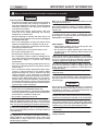 3
3
-
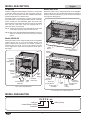 4
4
-
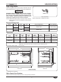 5
5
-
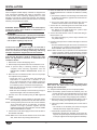 6
6
-
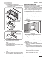 7
7
-
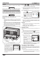 8
8
-
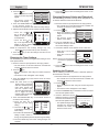 9
9
-
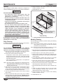 10
10
-
 11
11
-
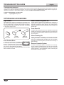 12
12
-
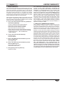 13
13
-
 14
14
-
 15
15
-
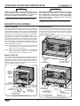 16
16
-
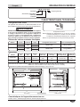 17
17
-
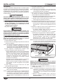 18
18
-
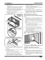 19
19
-
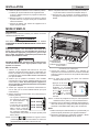 20
20
-
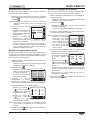 21
21
-
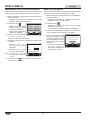 22
22
-
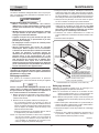 23
23
-
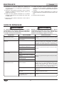 24
24
-
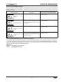 25
25
-
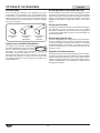 26
26
-
 27
27
-
 28
28


Hatco IHDCH Series Le manuel du propriétaire
- Taper
- Le manuel du propriétaire
dans d''autres langues
- English: Hatco IHDCH Series Owner's manual
Documents connexes
-
Hatco HDWTC Series Le manuel du propriétaire
-
-
-
-
-
-
Hatco C-12-208-3 Manuel utilisateur
-
Hatco C-36-240-3 Manuel utilisateur
-
Hatco C-7-208-3 Manuel utilisateur
-