
User manual
EN
Manuel de l’utilisateur
FR
Руководство пользователя
RU
Benutzerhandbuch
DE
DK50 DS


MEDICAL COMPRESSOR
MEDIZINALKOMPRESSOR
COMPRESSEUR POUR APPLICATIONS MÉDICALES
МЕДИЦИНСКИЙ КОМПРЕССОР
DK50 DS
EKOM spol. s r. o.
Priemyselná 5031/18
SK-921 01 Piešťany
Slovak Republic
tel.: +421 33 7967255
fax: +421 33 7967223
www.ekom.sk
email: ekom@ekom.sk
DATE OF LAST REVISION
DATUM DER LETZTEN ÜBERARBEITUNG
DATE DE LA DERNIÈRE MISE À JOUR
ДАТА ПОСЛЕДНЕГО ПЕРЕСМОТРА
11/2023
NP-DK50 DS-31_11-2023
112000053-000

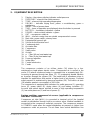
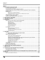
CONTENTS
4 NP-DK50 DS-31_11-2023
CONTENTS
1. GENERAL INFORMATION ...................................................................................................... 5
INTENDED USE .................................................................................................................. 5
CONTRAINDICATIONS AND SIDE-EFFECTS ................................................................... 5
OPERATOR'S RESPONSIBILITY FOR PATIENT SAFETY ................................................ 5
MARKINGS ......................................................................................................................... 5
WARNINGS ........................................................................................................................ 5
General safety warnings ............................................................................................ 6
Electrical system safety warnings .............................................................................. 6
WARNING NOTICES AND SYMBOLS ................................................................................ 7
USE ..................................................................................................................................... 8
STORAGE AND TRANSPORT ........................................................................................... 8
2. EQUIPMENT DESCRIPTION ................................................................................................... 9
3. TECHNICAL DATA .................................................................................................................12
4. OPERATION ...........................................................................................................................14
INSTALLATION AND FIRST OPERATION ........................................................................14
Removal of transport stabilizers ................................................................................15
Wheel installation ......................................................................................................15
Compressed air connection ......................................................................................15
Electrical connection .................................................................................................16
First operation ...........................................................................................................16
Accessories ..............................................................................................................17
PERSONNEL .....................................................................................................................18
Switching the compressor on ....................................................................................18
Running the compressor ...........................................................................................18
Alarm system ............................................................................................................19
Cleaning and replacing the filters ..............................................................................19
Cleaning the compressor ..........................................................................................19
5. MAINTENANCE ......................................................................................................................20
REPAIRS AND SERVICE...................................................................................................20
Cover removal ..........................................................................................................20
MAINTENANCE SCHEDULE ...........................................................................................21
Service interval signalization .....................................................................................21
Safety valve check ....................................................................................................21
Check tightness of joints and inspect the equipment .................................................22
Replacing filters elements .........................................................................................22
Setting outlet air pressure .........................................................................................23
Cleaning the pressure regulator ................................................................................23
Replacing the inlet filter (21)......................................................................................24
Stabilizing the compressor before shipping ...............................................................24
SHUT-DOWN .....................................................................................................................24
EQUIPMENT DISPOSAL ...................................................................................................24
BATTERY DISPOSAL ........................................................................................................24
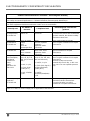
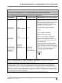
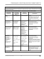
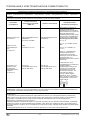
6. TROUBLESHOOTING.............................................................................................................25
7. SPARE PARTS .......................................................................................................................26
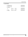
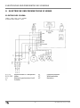
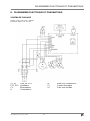
8. ELECTRIC AND PNEUMATIC DIAGRAMS ............................................................................27
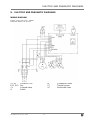
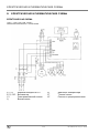
WIRING DIAGRAM ............................................................................................................27
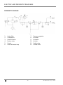
PNEUMATIC DIAGRAM .....................................................................................................28
9. ELECTROMAGNETIC COMPATIBILITY DECLARATION ......................................................29
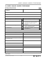
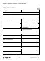
10. ANNEX .................................................................................................................................. 125
INSTALLATION RECORD................................................................................................ 125

GENERAL INFORMATION
NP-DK50 DS-31_11-2023 5
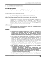
1. GENERAL INFORMATION
INTENDED USE
The EKOM DK50 DS is a medical air compressor that supplies clean, oil-free
compressed air for use with medical ventilators.
CONTRAINDICATIONS AND SIDE-EFFECTS
There are no contraindications or side-effects known.
OPERATOR'S RESPONSIBILITY FOR PATIENT SAFETY
The Installation, Operation and Maintenance Manual is an integral part of the
equipment and must be kept with the compressor. Careful review of this
manual will provide information necessary for correct operation of the
equipment.
Rx only
US Federal law restricts the sale of this device by or on the order of a
physician.
MARKINGS
Products marked with the CE mark of compliance meet the safety
requirements of the European Union (93/42/EEC).
WARNINGS
• The safety of operating personnel and trouble-free operation of the
equipment are ensured only if original parts are used. Only accessories
and spare parts mentioned in the technical documentation or expressly
approved by the manufacturer can be used.
• If any other accessories or consumable materials are used, the
manufacturer cannot be held responsible for the safe operation and
functionality of the equipment.
• The warranty does not cover damages resulting from the use of
accessories or consumable materials other than those recommended by
the manufacturer.
• The manufacturer assumes responsibility for the safety, reliability and
function of the equipment only if:
Installation, calibration, amendments, extensions and repairs are
performed by the manufacturer, one of its representatives or a service
provider authorized by the manufacturer
The equipment is used in accordance with the Installation, Operation
and Maintenance Manual
• The Installation, Operation and Maintenance Manual accurately describes
the design of the compressor and its compliance with safety and technical

GENERAL INFORMATION
6 NP-DK50 DS-31_11-2023
standards. The manufacturer reserves all rights to its wiring diagrams,
procedures and names.
• This user manual is the original instructions. Translation is performed in
accordance with the best available knowledge.
General safety warnings
The equipment is designed to operate safely when used correctly. Please
note the following safety measures to avoid injury or damage.
• Equipment operation must comply with all local codes and regulations.
• Original packaging should be kept for the possible return of the unit. Only
original packaging ensures optimal protection of the equipment during
transport. If it is necessary to return the equipment during the warranty
period, the manufacturer is not liable for damages caused by incorrect
packaging.
• The user must immediately notify the supplier if any problem occurs during
the use of the equipment.
• This product is not intended for use in areas where there is a risk of an
explosion. Do not operate the compressor in the presence of flammable
anesthetics.
• Never feed oxygen or nitrous oxide into the compressor. Compressor
components are not approved for oxygen or nitrous oxide use.
• The compressor must not be used for supplying air to the medical air
central distribution pipeline system.
Electrical system safety warnings
• The equipment must be connected to ground. I order to assure proper
grounding, connect the compressor to a receptacle marked "hospital
grade."
• Before the compressor is plugged in, make sure that the voltage and
frequency of the mains specified on the equipment are the same as the
power mains.
• Before operating, check for possible damage to the equipment and any
connections. Damaged pneumatic and electrical lines must be replaced
immediately.
• If a technical failure occurs, immediately disconnect the equipment from
the mains (pull out the main power plug).
• During repairs and maintenance, ensure that:
- The main power plug is removed from the power socket
- Compressed air lines are disconnected
- All pressure has been released from the air tank
• Only a qualified technician can install this equipment.

GENERAL INFORMATION
NP-DK50 DS-31_11-2023 7
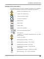
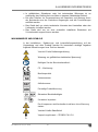
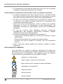
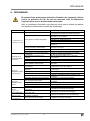
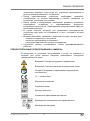
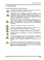
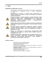
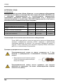
WARNING NOTICES AND SYMBOLS
The following symbols are used for important information in the Installation,
Operation and Maintenance Manual and on packaging and the product:
Attention, see instructions for use
Caution, risk of electric shock
Refer to instruction manual
CE mark of compliance
Medical device
Serial number
Article number
Unique Device Identifier
Swiss Authorised Representative
Swiss Importer
Compressor is controlled automatically and may start
without warning
Caution, hot surface
Handling mark on package – FRAGILE
Handling mark on package – THIS SIDE UP
Handling mark on package – KEEP DRY
Handling mark on package – TEMPERATURE
LIMITATIONS
Handling mark on package – LIMITED STACKING
Mark on package – RECYCLABLE MATERIAL

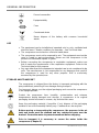
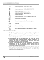
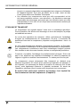
GENERAL INFORMATION
8 NP-DK50 DS-31_11-2023
Ground connection
Equipotentiality
Fuse
Condensate drain
Never dispose of the battery with common household
waste.
USE
• The equipment can be installed and operated only in a dry, ventilated and
dust-free area. Climatic conditions for operation - see Technical data.
• The compressor must stand on a flat and stable base.
• The compressor must not be exposed to rain. The equipment must not be
used in humid or wet environments. Never use the compressor in the
presence of flammable liquids or gases.
• Before connecting the compressor to respiration equipment, make sure
that it meets the requirements of the respiration equipment. Refer to the
Technical data for this purpose.
• Any use other than the compressor‘s intended use is not considered to be
safe. The manufacturer is not responsible for any damages that result if
the compressor is used for any other purpose. Risk is exclusively
assumed by the operator/user.
STORAGE AND TRANSPORT
The compressor is shipped from the factory in transport packaging with the
pump stabilized, protecting it from damage during transport.
For transport, always use the original packaging and secure the compressor
in the upright position.
Protect the compressor from humidity, contamination and extreme
temperatures during transport and storage. A compressor in its original
packaging should be stored in a warm, dry and dust-free area.
Keep the packaging material, if possible. If not, dispose of the packaging
material in an environmentally-friendly way. Cardboard can be recycled.
Before moving or transporting the compressor, the pressure in the air
tank and hoses must be released and any condensed water must be
drained. Secure the motor to prevent movement before shipping.
Prior to transport it is necessary to secure the motor inside the
compressor (Chapter 5.)

EQUIPMENT DESCRIPTION
NP-DK50 DS-31_11-2023 9
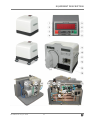
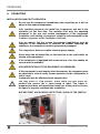
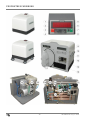
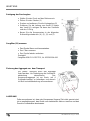
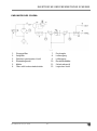
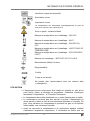
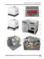
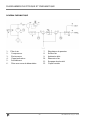
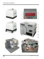
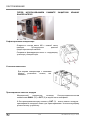
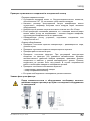
2. EQUIPMENT DESCRIPTION
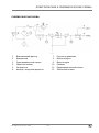
1. Display – the primary display indicates outlet pressure
2. PRESSURE - alarm at low outlet pressure
3. TEMP - alarm at high operating temperature
4. DRYING – indicates drying level; yellow = unsatisfactory, green =
satisfactory
5. MAINS – loss of power alarm
6. TIME – hours of operation are displayed when the button is pressed
7. BATTERY – low battery indication = yellow
8. POWER – device status indicator = green
9. OUT – compressor outlet air
10. WALL - inlet air coming from an outside compressed air source
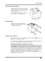
11. Main inlet, power switch, primary fuses
12. Equipotential (ground) pin
13. Socket for the electrical cord
14. Condensate tank
15. Air intake filter
16. Compressor
17. Safety valve
18. Air tank
19. a. Filter (40 μm) and water trap
19. b. Filter (5 μm) and water trap
20. Pressure regulator
21. Intake filter
22. Control electronics
23. Cooler
The compressor contains of an oil-free piston (16) driven by a low-
maintenance single-phase electric motor. Compressed air is cooled in the
cooler (23) where condensed water is separated into a separate tank (14).
Incoming air passes through two filters (15, 21) undergoing double filtration
as it passes through the system (19). The model with a membrane dryer is
intended for applications that require a higher level of air dryness. Constant
outlet pressure is maintained by pressure regulator (20). The built-in air tank
(18) enables peak air consumption of 200 L/min.
The compressor is equipped with indicators for outlet pressure (1), operating
hours (6), power status (8), drying status (4) and battery condition (7).
Acoustic and optical alarms activate to warn of high operating temperature
(3), low outlet pressure (2) and loss of power (5).
Backup ventilator compressed air source (applicable to compressors
with WALL connection)
Compressor air inlet (WALL) is connected to terminal unit of the hospital
central air distribution through built-in non-return valve. Medical ventilator is
connected to the compressor outlet air connector. The compressor remains
in STANDBY mode when the central distribution air pressure is higher than
compressor outlet air pressure. The air flows from central distribution line

EQUIPMENT DESCRIPTION
10 NP-DK50 DS-31_11-2023
through compressor air inlet (WALL), non-return valve and compressor air
outlet to the ventilator.
If the air pressure in central distribution drops below compressor outlet air
pressure, the controller automatically starts up the compressor, which
delivers air directly to ventilator. Air delivery from the compressor to the
central air distribution pipeline is prevented by non-return valve.
Primary ventilator compressed air source
The compressor continuously supplies compressed air directly to the medical
ventilator when the central compressed air distribution line is not connected
to compressor air inlet (WALL).
If air consumption is zero, the device switches to STANDBY mode.
The compressor must not be used for supplying air to the medical air
central distribution pipeline system. Do not connect compressor air
outlet to the central distribution pipeline system.

EQUIPMENT DESCRIPTION
NP-DK50 DS-31_11-2023 11

TECHNICAL DATA
12 NP-DK50 DS-31_11-2023
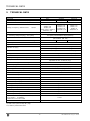
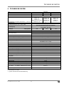
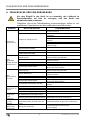
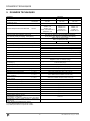
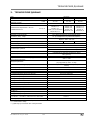
3. TECHNICAL DATA
TYPE
DK50 DS
VERSION
basic
standard
advanced
Outlet flow at pressure 3.5 bar (51 psig)
Liters/min
40 / 32*
50 / 40*
60 / 50*
Peak flow
200** L/min ( 7 Cft/min )
Voltage / Frequency / Rated current
V/Hz/A
230/50 / 2.8
230/60 / 2.8
115/60 / 5.6
120/60 / 5.6 UL model***
100/50-60 / 5.6
230/50 / 2.8
230/60 / 2.8
115/60 / 5.6
100/50-60 / 5.6
230/50 / 3.3
230/60 / 3.9
115/60 / 6
100/50-60 / 6
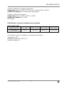
Air filtration
m
5
Pressure dew point at 40 L/min
( 1.4 Cft/min), 3 bar( 43.5 psig ), 20°C (68°F)
5°C (9°F) below the ambient temperature
10°C (18°F) with membrane dryer (optional)
Outlet connection
DISS 1160-A (3/4"-16 UNF)
optional NIST (EN 739)
Sound level dB(A) @50Hz
≤49
≤50
≤51
Mode of operation
Continuous - S1
Separation of condensed water
Automatic
Indication of drying
Yellow (working pressure < 4 bar (58 psig) )
Green (working pressure ≥ 4 bar (58 psig) )
Low pressure alarm
Decrease in outlet pressure under 2.1 bar ( 30.5 psig )
Cooling failure alarm
Increase in internal temperature above 80°C (176°F)
Power failure alarm
yes
Auditory alarm signal - acoustic pressure dB(A)
≥60**** / ≥65
Outlet pressure
3.0 bar (43 psig)
Adjustable to max. 3.5 bar (51 psig)
Automatic start up pressure (backup)
Air tank capacity
2 L (0.61gall UK)
Pressure range
5 bar ( 72.5 psig ) – 6.5 bar ( 94 psig)
Operating pressure of safety valve
7 bar ( 101.5 psig )
Adjustment of outlet air pressure
Pressure regulator
Dimensions of compressor
w x d x h
445 x 355 x 440 mm ( 17.5 x 14 x 17 in )
Dimensions of compressor with weels
w x d x h
470 x 380 x 520 mm ( 18.5 x 15x 20.5 in )
Dimensions of compressor with trolley
w x d x h
535 x 575 x 1054 mm ( 21 x 22,5 x 41.5 in )
Dimensions of packaging
w x d x h
510 x 480 x 470 mm ( 20 x 19 x 18.5 in )
Dimensions of packaging
560 x 630 x 760 mm ( 22 x 25 x 30 in )
Net weight
34 kg ( 75 lbs )
Net weight of compressor with weels
36 kg ( 80 lbs )
Net weight of compressor with trolley
45 kg ( 99 lbs )
Gross weight
41 kg ( 91 lbs )
Gross weight of compressor with weels
43 kg ( 95 lbs )
Gross weight of compressor with trolley
60 kg ( 132 lbs )
Implementation according to EN 60601-1, EN 12021
*** UL Model – UL 60601-1,
CAN/UCSA.C22.2 601.1-M90
Class I.
Classification acc. to MDD 93/42 EEC, 2007/47 EC
II b
*) with membrane dryer (optional)
**) With 0.6 bar pressure drop (8.7 psig)
****) valid for power failure alarm

TECHNICAL DATA
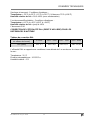
NP-DK50 DS-31_11-2023 13
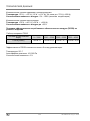
Climatic conditions for storage and transport
Temperature –25°C to +55°C (-13°F to +131°F), 24 hrs +70°C (+158°F)
Relative air humidity 0% to 100% (with condensation)
Climatic conditions for operation
Temperature +15°C to +40°C (+59°F to +104°F)
Relative air humidity up to +95%
IPX0 Rating
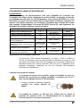
FAD efficiency correction for differences in elevation
FAD correction table
Elevation [mamsl]
0 - 1500
1501 - 2500
2501 - 3500
3501 - 4500
FAD [l/min]
FAD x 1
FAD x 0.8
FAD x 0.71
FAD x 0.60
FAD efficiency refers to conditions at an elevation of 0 mamsl:
Temperature: 20°C
Atmospheric pressure: 101325 Pa
Relative humidity: 0%

OPERATION
14 NP-DK50 DS-31_11-2023
4. OPERATION
INSTALLATION AND FIRST OPERATION
Do not use the compressor immediately after unpacking as it will not
adjust to the ambient temperature.
Only qualified personnel can install the compressor and put it into
operation for the first time. The installer shall train the operating
personnel in the use and routine maintenance of the equipment.
Installation and training of personnel should be acknowledged by the
installer‘s signature on the installation certificate.
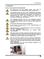
Prior to start-up, the four screws for transport stabilization must be
removed. If the compressor is switched on without removing the
stabilizers, the compressor could be permanently damaged.
The compressor does not contain a backup power supply.
Never block the air intake filter on the backside or the vent outlets on
the top of the equipment.
If the compressor is equipped with a main source of air, the standby air
source must be available.
ANY MODIFICATION OF THIS EQUIPMENT IS FORBIDDEN!
If this equipment is used nearby other instruments, the equipment must
be observed in order to verify normal operations in the configuration it
will be used.
Instruments may be affected electro-magnetically!
You may notice a “new product” odour when you first place the
product into service (for a short period of time). This odour is
temporary and does not impede the normal use of the product. Ensure
the space is properly ventilated after installation.
BEFORE FIRST USE REMOVE PROTECTIVE COVER OF THE SWITCH!

OPERATION
NP-DK50 DS-31_11-2023 15
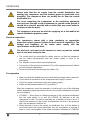
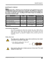
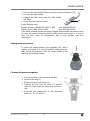
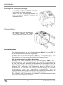
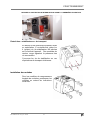
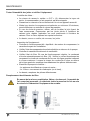
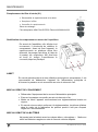
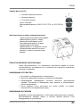
Removal of transport stabilizers
On the bottom of the unit are four M6
stabilizing screws that must be removed
before start-up. They are marked with a
red warning washer.
Please retain the stabilizing screws for
future transport of the compressor.
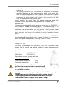
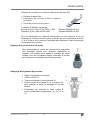
Wheel installation
Wheels must be installed following
the figure below for versions of the
compressor with wheels.
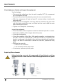
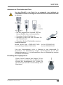
Compressed air connection
The medical compressor is equipped with quick couplings WALL (10) and
OUT (9) on the rear of the cabinet.
Connect the pressure hose from the given equipment/respiration equipment
to the quick coupling OUT (9) -outlet compressed air.
Applicable to compressors with WALL connection:
Connect the compressed air line from the central distribution line o the quick
coupling WALL (10) -inlet compressed air. Air from the distribution system is
automatically connected through the compressor to the OUT outlet port. In
this configuration, the compressor serves as a backup source of compressed
air. If the air pressure from the central distribution system is reduced, the
compressor automatically switches on and there is no interruption in the
supply of continuously pressurized air at the outlet of the compressor.
Air delivery from the compressor to the central air distribution pipeline is
prevented by non-return valve.

OPERATION
16 NP-DK50 DS-31_11-2023
Please note that the air supply from the central distribution line
entering the compressor must be medical grade air (particulate size,
humidity.) The compressor does not modify the air from the central
distribution line.
The hose connecting the compressor to the respiration equipment
must not pass through a cold environment i.e. placed on the ground. It
should be as short as possible with no kinks (this may cause water to
condense inside the hose).
The compressor must not be used for supplying air to the medical air
central distribution pipeline system.
Electrical connection
The compressor comes with a plug containing an appropriate
protective contact (ground.) Adhere to local electrical regulations. The
voltage and frequency of the mains must comply with the
specifications on the data label.
The electrical cord must not be stressed or have any tension exerted
upon it, and must always be free.
• The socket must be accessible for safety reasons so that the equipment
can be safely disconnected from the power supply in case of an
emergency.
• The relevant current circuit must be protected.
• Connection of the ground connection (12) to other equipment must adhere
to local electrical regulations.
• Fasten the electrical cord through the holder (13).
First operation
• Make sure that the stabilizing screws used during transport were removed.
• Check that the connection to the compressed air supply is correct.
• Check for proper connection to the main power supply.
• Switch on the pressure switch (11) to position “I”.
After the compressor is put into operation, it shall work in one of the following
modes depending upon the pressure level in the central distribution and upon
air consumption.
• STANDBY – When there is sufficient pressure in the central air distribution
line, the main switch is on and the POWER (8) indicator is on, the
compressor is idle. The device operates as a standby source of air as it
checks the pressure in the central air distribution line and, if the pressure
falls, the compressor switches on.
• When pressure is low in the central air distribution line, or if the device is
not connected to the central distribution line, the compressor is running. If
there is no air consumption at the outlet, the device switches to STANDBY

OPERATION
NP-DK50 DS-31_11-2023 17
mode. When air consumption resumes, the compressor automatically
switches on.
• The working pressure in the air tank when the compressor is running is
maintained between the high and low pressure limits by the control unit.
After the high working pressure limit is reached, the compressor output is
connected to the exhaust (bypass) and the compressor stops supplying
compressed air to the air tank until as long as the pressure in the tank
does not drop below the low pressure limit.
During operation, the device drains the trapped condensed water from
pneumatic circuits via automatic filter separators into a separate tank.
Important note:
If compressor equipped with set of membrane dryer ( art. nr.: 603021320 )
and compressor is not connected to WALL ( central air supply ), the
compressor does not switch into STAND BY. In order to maintain the
membrane dryer unit active the dryer unit requires a small constant flow of
compressed air. Compressor works in RUN mode only. The compressor
stops and starts only when it is switched off and on manually by power
switch.
If compressor equipped with set of membrane dryer ( art. nr.: 603021320 )
and compressor is connected to WALL ( central air supply ), the compressor
works in complete mode operation, including STAND BY mode.
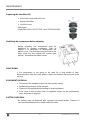
Accessories
Trolley SD 30 (24)
The trolley accommodates the compressor, a fan and a humidifier. Large
casters allow for mobility and braking, guided by means of an ergonomic
handle. A wide base ensures the stability of the entire assembly.
Specifications
Supply No.: 602021222-000
Dimensions: 535x575x1070
Maximal load-carrying capacity with load
in the upper plate axis (1):
Trolley without compressor - 25kg
Trolley with compressor - 30kg
The manufacturer is not liable for any damage
resulting from excessive loads on the equipment!
The supplier is obliged to ensure the acceptability of a load delivered
by a supplied accessory.
It is forbidden to lean or press against an installed accessory for
support!
The equipment must be lifted when travelling over an obstacle!
Supporting equipment must be disassemble before transport!
The maximum load on the upper trolley plate is 30 kg!

OPERATION
18 NP-DK50 DS-31_11-2023
Humidifier holder (25)
This clamp is used to attach the Fischer & Paykel humidifier to the trolley in
its proper position.
Supply No. 604031175-000
PERSONNEL
The equipment may only be operated by the trained staff!
In case of emergency, switch the equipment off at the switch and pull
out the main power plug.
Switching the compressor on
The compressor is switched on at the main power switch (11) by putting it in
position "I". Switching on is signaled by the green indicator (8).
Running the compressor
The green indicator POWER (8) is lit up during operation. The display shows
the value of outlet pressure with accuracy ± 5% in BAR or PSI units. An
indicator is lit on the display next to the relevant unit. Ask the service staff
member to change the units that are shown if necessary.
115V version -
After pressing the TIME (6) button, the display shows the number of hours in
operation.
230V version -
After pressing the TIME (6) button, the display shows the number of hours in
operation. The compressor operating hours since the last service work are
displayed by pressing the button for about 2 seconds.
The calculated running interval is set to a coefficient of 1.0 if the compressor
is supplying compressed air to the air tank. The calculated coefficient is 0.3
in “BYPASS” mode. The DRYING (4) indicator displays the drying status.
Green indicates satisfactory drying; yellow indicates unsatisfactory drying. If
the yellow indicator DRYING (4) stays on, make sure that air consumption
from the compressor does not exceed outlet flow according to specification. If
air consumption is within normal parameters, contact a service centre.
Illumination of the yellow indicator BATTERY (7) indicates a low battery. The
battery is charged automatically during equipment operation. If the yellow
control light does not turn off after 24 hours of the equipment operation, it is
necessary to change the battery. The battery powers the MAINS (5) alarm
and has no impact on other functions of the device. Entrust an authorized
service provider with its replacement. Replace the battery with an identical
replacement - NiMH 9V 200mAh.
Used batteries cannot be disposed of as household waste, they must be
collected separately.
The condensed liquid drains into a separate tank (14) at the back of the
equipment. When the tank fills up, it must be emptied.

OPERATION
NP-DK50 DS-31_11-2023 19
Close the plug located on the neck of the vessel before moving any
vessel containing a liquid!
Alarm system
All alarm states of the equipment are states of the middle priority technical
alarm according to EN 60601-1-8. Each alarm state is indicated by the
corresponding visual and auditory signal (see Chapter 2 - Display Unit and
Chapter 3 - Technical Data).
Alarm states indicate a potential failure of the device. Therefore, it is not
possible to deactivate the alarm signals.
All alarm signals are non-latching – after the triggering event no longer exists
the alarm signals stop.
Low pressure. A decrease in outlet pressure is indicated by the alarm
PRESSURE (2) which sounds an alarm and illuminates the yellow indicator.
The alarm is activated if the outlet pressure does not reach the required level
and in the interval after the compressor is turned on until it reaches the
required pressure. If the alarm stays on, make sure that the air consumption
does not exceed outlet flow according to specification. If air consumption is
within normal parameters, contact a service centre.
High temperature. A cooling failure is indicated by the alarm TEMP (3)
which sounds an alarm and illuminates the yellow indicator. The device must
be immediately disconnected from the electrical mains and cooled down.
Cooling failure activation may indicate that the vent holes were covered, the
filter in the bottom part of the compressor is contaminated or the compressor
is in environment with higher temperature. If none of these circumstances
apply, a malfunction has occurred and service is required.
Power failure. The alarm MAINS (5) is activated upon the interruption in the
power supply to the compressor.
Operators must quickly secure a backup air source for the patient in the
event any of these signals activate during equipment operation.
Test of the alarm system functionality is performed automatically when the
equipment is switched on by a short testing activation of the visual and
auditory alarm signals (light up of LED indicator and auditory pulse).
Cleaning and replacing the filters
At least once a week take out and clean the suction filter (15) located on the
back side. Wash the filter in warm soapy water, rinse thoroughly and allow it
to dry. Insert the clean filters so that the intake openings are completely
covered by the filters.
Cleaning the compressor
To clean the compressor, use a detergent that contains no abrasives,
chemical solvents or other corrosive agents.

MAINTENANCE
20 NP-DK50 DS-31_11-2023
5. MAINTENANCE
REPAIRS AND SERVICE
Warranty and extended warranty repairs are to be completed by the
manufacturer or a service provider authorized by the manufacturer.
The manufacturer reserves the right to modify the equipment in any
way that will not alter the function or the operation of the equipment.
Only a qualified technician or the Customer Service Department of the
manufacturer may perform repairs that go beyond routine maintenance.
Use only spare parts and accessories approved by the manufacturer.
Prior to any maintenance or repairs, switch off the compressor and
disconnect it from the mains (pull out the main power plug).
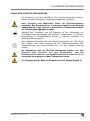
Air pump components (head, cylinder, pressure hose, etc.) are very hot
during and shortly after compressor operation – do not touch these
components!
Allow the equipment to cool down before maintenance, service or
connecting/disconnecting the compressed air supply!
Automatic start: when pressure in the pressure tank decreases below
the switch-on pressure, the compressor automatically switches on. The
compressor automatically switches off when pressure in the air tank
reaches the switch-off pressure.
Cover removal
- Unscrew the 6 screws from the rear cover
- Disconnect the grounding wire
- Remove the rear cover
- Disconnect the wiring connector for the display and pull the wiring out from
the opening in the frame
- Unscrew the 4 screws from the rear of the main cover and 2 screws from
the rear part of the rail
- Disconnect the grounding wire
- Remove the main cover
- Reassemble using the opposite order
La page est en cours de chargement...
La page est en cours de chargement...
La page est en cours de chargement...
La page est en cours de chargement...
La page est en cours de chargement...
La page est en cours de chargement...
La page est en cours de chargement...
La page est en cours de chargement...
La page est en cours de chargement...
La page est en cours de chargement...
La page est en cours de chargement...
La page est en cours de chargement...
La page est en cours de chargement...
La page est en cours de chargement...
La page est en cours de chargement...
La page est en cours de chargement...
La page est en cours de chargement...
La page est en cours de chargement...
La page est en cours de chargement...
La page est en cours de chargement...
La page est en cours de chargement...
La page est en cours de chargement...
La page est en cours de chargement...
La page est en cours de chargement...
La page est en cours de chargement...
La page est en cours de chargement...
La page est en cours de chargement...
La page est en cours de chargement...
La page est en cours de chargement...
La page est en cours de chargement...
La page est en cours de chargement...
La page est en cours de chargement...
La page est en cours de chargement...
La page est en cours de chargement...
La page est en cours de chargement...
La page est en cours de chargement...
La page est en cours de chargement...
La page est en cours de chargement...
La page est en cours de chargement...
La page est en cours de chargement...
La page est en cours de chargement...
La page est en cours de chargement...
La page est en cours de chargement...
La page est en cours de chargement...
La page est en cours de chargement...
La page est en cours de chargement...
La page est en cours de chargement...
La page est en cours de chargement...
La page est en cours de chargement...
La page est en cours de chargement...
La page est en cours de chargement...
La page est en cours de chargement...
La page est en cours de chargement...
La page est en cours de chargement...
La page est en cours de chargement...
La page est en cours de chargement...
La page est en cours de chargement...
La page est en cours de chargement...
La page est en cours de chargement...
La page est en cours de chargement...
La page est en cours de chargement...
La page est en cours de chargement...
La page est en cours de chargement...
La page est en cours de chargement...
La page est en cours de chargement...
La page est en cours de chargement...
La page est en cours de chargement...
La page est en cours de chargement...
La page est en cours de chargement...
La page est en cours de chargement...
La page est en cours de chargement...
La page est en cours de chargement...
La page est en cours de chargement...
La page est en cours de chargement...
La page est en cours de chargement...
La page est en cours de chargement...
La page est en cours de chargement...
La page est en cours de chargement...
La page est en cours de chargement...
La page est en cours de chargement...
La page est en cours de chargement...
La page est en cours de chargement...
La page est en cours de chargement...
La page est en cours de chargement...
La page est en cours de chargement...
La page est en cours de chargement...
La page est en cours de chargement...
La page est en cours de chargement...
La page est en cours de chargement...
La page est en cours de chargement...
La page est en cours de chargement...
La page est en cours de chargement...
La page est en cours de chargement...
La page est en cours de chargement...
La page est en cours de chargement...
La page est en cours de chargement...
La page est en cours de chargement...
La page est en cours de chargement...
La page est en cours de chargement...
La page est en cours de chargement...
La page est en cours de chargement...
La page est en cours de chargement...
La page est en cours de chargement...
La page est en cours de chargement...
La page est en cours de chargement...
La page est en cours de chargement...
La page est en cours de chargement...
La page est en cours de chargement...
La page est en cours de chargement...
La page est en cours de chargement...
La page est en cours de chargement...
La page est en cours de chargement...
-
 1
1
-
 2
2
-
 3
3
-
 4
4
-
 5
5
-
 6
6
-
 7
7
-
 8
8
-
 9
9
-
 10
10
-
 11
11
-
 12
12
-
 13
13
-
 14
14
-
 15
15
-
 16
16
-
 17
17
-
 18
18
-
 19
19
-
 20
20
-
 21
21
-
 22
22
-
 23
23
-
 24
24
-
 25
25
-
 26
26
-
 27
27
-
 28
28
-
 29
29
-
 30
30
-
 31
31
-
 32
32
-
 33
33
-
 34
34
-
 35
35
-
 36
36
-
 37
37
-
 38
38
-
 39
39
-
 40
40
-
 41
41
-
 42
42
-
 43
43
-
 44
44
-
 45
45
-
 46
46
-
 47
47
-
 48
48
-
 49
49
-
 50
50
-
 51
51
-
 52
52
-
 53
53
-
 54
54
-
 55
55
-
 56
56
-
 57
57
-
 58
58
-
 59
59
-
 60
60
-
 61
61
-
 62
62
-
 63
63
-
 64
64
-
 65
65
-
 66
66
-
 67
67
-
 68
68
-
 69
69
-
 70
70
-
 71
71
-
 72
72
-
 73
73
-
 74
74
-
 75
75
-
 76
76
-
 77
77
-
 78
78
-
 79
79
-
 80
80
-
 81
81
-
 82
82
-
 83
83
-
 84
84
-
 85
85
-
 86
86
-
 87
87
-
 88
88
-
 89
89
-
 90
90
-
 91
91
-
 92
92
-
 93
93
-
 94
94
-
 95
95
-
 96
96
-
 97
97
-
 98
98
-
 99
99
-
 100
100
-
 101
101
-
 102
102
-
 103
103
-
 104
104
-
 105
105
-
 106
106
-
 107
107
-
 108
108
-
 109
109
-
 110
110
-
 111
111
-
 112
112
-
 113
113
-
 114
114
-
 115
115
-
 116
116
-
 117
117
-
 118
118
-
 119
119
-
 120
120
-
 121
121
-
 122
122
-
 123
123
-
 124
124
-
 125
125
-
 126
126
-
 127
127
-
 128
128
-
 129
129
-
 130
130
-
 131
131
-
 132
132


dans d''autres langues
- Deutsch: EKOM DK50 DS Benutzerhandbuch
Documents connexes


Autres documents
-
Ingersoll Rand 23231806 Manuel utilisateur
-
Ingersoll-Rand D54IN Manuel utilisateur
-
-
-
-
-
Danfoss Application Handbook - Automatic Controls for Industrial Refrigeration Systems Mode d'emploi
-