

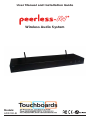
2 of 16 ISSUED: 08-30-13 SHEET #: 180-9051-1
Contents
Important Safety Instructions ......................................................................................................... 3
Important Information ..................................................................................................................... 4
Unit Care Recommendations ......................................................................................................... 4
Specifi cations .................................................................................................................................. 5
Introduction ...................................................................................................................................... 6
What’s In The ADS100-B Box ........................................................................................................... 6
Tools Needed For Installation ........................................................................................................ 6
Installation Planning ...................................................................................................................... 6
Installation ........................................................................................................................................ 7
Product Overview .......................................................................................................................... 7
Transmitter: Mounting .................................................................................................................... 9
Transmitter: Power Connections ................................................................................................... 9
Transmitter: Antenna And Cable Connections ............................................................................... 9
Transmitter: TX Module Connections .......................................................................................... 10
Transmitter: Input Signal Connection - Speaker Level Option .................................................... 10
Transmitter: Input Signal Connection - Line Level Audio Option ................................................. 10
In-Wall Installation of the ADS100-A252 Wireless Receiver/Amplifi er .........................................11
Transmitter and Amplifi er Pairing ................................................................................................ 12
Stereo vs Mono Setup ................................................................................................................. 12
Multiple Amplifi ers to Same Inputs .............................................................................................. 12
Power Outages ............................................................................................................................ 12
Finalizing The Installation ............................................................................................................ 13
FAQs ............................................................................................................................................... 14
Limited Warranty ........................................................................................................................... 15

3 of 16 ISSUED: 08-30-13 SHEET #: 180-9051-1
Important Safety Instructions
Warnings/Safety
1. Read these instructions.
2. Keep these instructions.
3. Heed all warnings.
4. Follow all instructions.
5. Do not use this apparatus near water.
6. Clean only with dry cloth.
7. Do not block any ventilation openings. Install in accordance with manufacturer’s instructions.
8. Do not install near any heat sources such as radiators, heat registers, stoves, or other apparatus
(including amplifi ers) that produce heat.
9. Do not defeat the safety purpose of the polarized or grounding-type plug. A polarized plug has two
blades with one wider than the other. A grounding type plug has two blades and a third grounding
prong. The wide blade or the third prong are provided for your safety. If the provided plug does not fi t
into your outlet, consult an electrician for replacement of the obsolete outlet.
10. Protect the power cord from being walked on or pinched particularly at plugs, convenience
receptacles, and the point where they exit from the apparatus.
11. Only use attachments/accessories specifi ed by the manufacturer.
12. Use only with the cart, stand, tripod, bracket, or table specifi ed by the manufacturer, or sold with
the apparatus.
13. Unplug this apparatus during lightning storms or when unused for long periods of time.
14. Refer all servicing to qualifi ed service personnel. Servicing is required when the apparatus has
been damaged in any way, such as power-supply cord or plug is damaged, liquid has been spilled or
objects have fallen into the apparatus, the apparatus has been exposed to rain or moisture, does not
operate normally, or has been dropped.
15. The product was submitted and evaluated for use at the maximum ambient (Tma)ἁ 40°C
16. WARNING: To Reduce The Risk Of Fire Or Electric Shock, Do Not Expose This Apparatus To
Rain Or Moisture. Apparatus shall not be exposed to dripping or splashing and no objects fi lled with
liquids, such as vases, shall be placed on the apparatus..
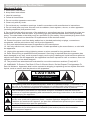
CAUTION
RISK OF ELECTRIC SHOCK!
DO NOT OPEN!
ATTENTION ! RISQUE DE CHOC ! ÉLECTRIQUE PAS OUVRIR !
The lightning fl ash with arrowhead symbol, within an equilateral triangle, is intended to alert
the user to the presence of uninsulated dangerous voltage within the product's enclosure
that may be a suffi cient magnitude to constitute a risk of electric shock to persons.
The exclamation point within an equilateral triangle is intended to alert the user to the
presence of important operating and maintenance (servicing) instructions in the literature
accompanying the appliance.
Le symbole de l'éclair avec une fl èche à son extrémité, dans un triangle équilatéral, a pour
but de vous avertir de la présence d'une « tension électrique dangereuse » et non isolée à
l'intérieur de l'enceinte de l'appareil, qui peut être suffi samment puissante pour constituer
un risque d'élctrocution pour les personnes
Le point d'excalamation dans un triangle équilatéral vous avertit de l'existence d'instructions
importantes de fonctionnement et d'entretien (intervention) dans la documnetation
accompagnant l'appareil.

4 of 16 ISSUED: 08-30-13 SHEET #: 180-9051-1
Model:ADS100-A252
FCC ID: 2AAW2ADS100-A252
This device complies with part 15 of the FCC Rules. Operation is subject to the following two
conditions: (1) This device may not cause harmful interference, and (2) this device must accept any
interference received, including interference that may cause undesired operation.
Model:ADS100-T8
FCC ID: 2AAW2ADS100-T8
This device complies with part 15 of the FCC Rules. Operation is subject to the following two
conditions: (1) This device may not cause harmful interference, and (2) this device must accept any
interference received, including interference that may cause undesired operation.
17. Avoid overloading electrical outlets or extension cords which otherwise could result in electric
shock or fi re.
18. To avoid electric shock, never stick anything in the slots on the case or remove the cover.
19. This product is intended for indoor use only.
20. The apparatus shall be connected to a mains socket outlet with a protective earthing connection.
Important Information
• Never use this product in an aircraft or a medical facility. It can cause interference or an
undesirable effect.
• The use of this product in the following locations may result in an abnormal audio output (noise,
etc,).
º Near a refrigerator or metal structure.
º In a cluttered room, causing potential blocked wireless signals.
• This product has been tested and manufactured to comply with each country’s safety rules.
However, there is no guarantee that interference will not occur in some installations. If
interference happens, decrease the distance between the product and receiving antenna.
• Optimal use of this product is for in-room/multi-room applications with a range of up to 140 ft.
(43m) away line-of-sight (LOS). This distance is reduced slightly when objects like walls and
fl oors are in the transmission path.
• Any changes or modifi cations not expressly approved by the manufacturer of this device could
void the product warranty.
• This equipment must be installed and operated in accordance with the provided instructions.
End users and installers must be provided with installation instructions and Transmitter operating
conditions for satisfying RF exposure compliance.
• This device should be used only as specifi ed within this manual to meet RF exposure
requirements. Use of this device in a manner inconsistent with this manual could lead to
excessive RF exposure conditions.
Unit Care Recommendations
To clean, use a soft, dry cloth only. Do not use water or other cleaning products as they may cause
electrical failure or damage the surface of the product.

5 of 16 ISSUED: 08-30-13 SHEET #: 180-9051-1
SPECIFICATIONS
T8 Transmitter
• Size: 17 ¼”w x 1 11/32” h x 7”d
• Rack Height: 1U
• Power Input: 120/240 VAC 50/60Hz to supplied AC adapter (5VDC @ 1000 mW)
• Line Level Inputs: Qty 8 independent RCA
• Speaker Level Inputs: Qty 8 independent, 150 watts max each, 2 pole plug
• Mounting: Rack or surface
• Frequency band: 2.4 GHz, spread spectrum
• Wireless distance: 140 ft*
• Streaming: 16 Bit, 48 KHz rate with error checking
• Adaptive Frequency Hopping:Yes, 18 channels with 4 active, 14 on trial
• Latency: 42.7 mS
• Antenna cable: RG316D Coax, double shield with reverse thread fi ttings, 10 ft.
• Agency Approvals: UL60065, CE, LVD, FCC
* Actual distance will be reduced with obstructions between transmitter and receiver modules
A252 Amplifi er
• Size: 4”h x 4 1/8”w x 1 ½”d
• Power Input: 100/240 VAC 50/60Hz direct, 150 watts maximum (with protective
ground required)
• Power Connection: 2 wire spring hold push in, screw terminal ground, wired or conduit per
Electric Code
• Speaker Connection: Qty 2 – 2 pole screw clamp plug
• Impedance: 8 ohm
• Power Output: 25 watts x 2 @ <0.1% THD+N(1 W, 1KHz)
• Signal to Noise: 110 dB
• Protection: Over temperature, overload, short circuit, with power cycle reset
• Mounting: In-wall, On-wall, UL 2043 Plenum area’s (with proper UL 2043
accessories)
• Agency Approvals: UL60065, UL 2043, CE, LVD, FCC

6 of 16 ISSUED: 08-30-13 SHEET #: 180-9051-1
Introduction
The Peer Sound Wireless Audio System provides for eight total independent channels, four total
stereo zones or any combination in-between. By connecting your source(s) to either the RCA line
level or speaker level inputs, you can wirelessly transmit the audio signal and amplify it for the remote
speakers. This system works with any brand speakers or sources (amplifi er or preamp).
The installation process starts with a little planning and understanding the options you have for
installation.
(1) ADS100-T8 Transmitter Kit
• (1) pair of rack ears + Screws
• (1) ADS100-TX14 TX Module Kit
• SCR M2x.4 x 4MM PAN HD PHL BLK
• (1) ADS100-A252 Amplifi er Kit
• In-wall holder for amp
• In-wall bracket screw for amp
• (2) Drywall clamp w/ screws
• (1) Conduit adapter bracket
• (1) 2 Gang oversize wall plate w/ screws
• (1) ADS100-RXS RX Stereo Module Kit
• SCR M2x.4 x 4MM PAN HD PHL BLK
• (1) ADS100-RAC10 TX Remote Cable Kit
• TX remote cable, 10'
• In-wall amp template
• Antenna remote mount bracket
• System instructions
Tools Needed For Installation
• Bubble Level
• Phillips Screwdriver
• Small straight screwdriver
• Drywall Saw
• Wire Strippers
• Side Cutters
• Tape Measure
• Pencil
Installation Planning
There is fl exibility in the component installations.
First: Options for the transmitter:
• Place unit on a fl at surface (like cabinet)
• Place unit inside a standard AV rack assembly
• Local or remote antenna mounting options. A 10ft thin coax cable is provided for remote
antenna mounting. The cable has a bulkhead fi tting that allows for 0.10” (2.54mm) thickness.
Second: Flexible amplifi er/receiver installation options:
• Inside a drywall cavity (fl ush to the outer surface). The maximum drywall thickness is 5/8”.
• Attached to a structure, such as ceiling beams
• On top of a wall surface (requires accessory kit ADS100-OWK)
• In a UL 2043 plenum area (requires UL 2043 plenum wiring, tie wraps, etc)
It helps to have your amplifi er locations in mind when starting the installation process. Generally, the
amplifi er is placed near a 120/240 VAC power source, capable of 150 watts peak demand.
Tip: While this device does not require Line-of-Sight, the signal can still be effected by certain building materials. For
best wireless performance, try to keep cement or a lot of steel (like ductwork or a refrigerator) out of the imaginary
line-of-sight between transmitter and receivers.
What’s In The ADS100-B Box
Before you start the installation, make sure you have the following items:

7 of 16 ISSUED: 08-30-13 SHEET #: 180-9051-1
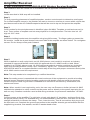
Installation
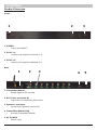
Product Overview
Front
1. POWER
• Turns unit ON/OFF
2. SYNC 1-4
• Used to pair amps for channels 1-4
3. SYNC 5-8
• Used to pair amps for channels 5-8
Back
1. Transmitter Module
• Sends signal to RX on amp
2. RCA Line Level Input (8)
• Inputs for AV component connection
3. Speaker Level Input
• Inputs for AV speaker connection
4. Transmitter Module Plug
• Accepts Transmitter Module
5. DC POWER
• Power input
123
123 54

8 of 16 ISSUED: 08-30-13 SHEET #: 180-9051-1
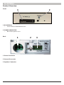
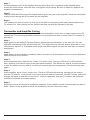
Installation
Product Overview
Front
1. RX MODULE
• Insert RXS or RXM Module here
2. POWER INDICATOR
• Blue when power is on.
Back
1. Power Connector
2. Ground Connector
3. Speaker Connector
12
12 3

9 of 16 ISSUED: 08-30-13 SHEET #: 180-9051-1
Installation
Transmitter
Mounting
If the transmitter will not be installed in an AV rack, then leave the rubber feet in place. If the
transmitter will be installed in an av rack, then remove the four rubber feet from the base.
Step 1
Use the supplied M3 screws to install the rack ears onto the chassis.
Step 2
Mount the Transmitter into the rack.
Power Connections
Step 1
Connect the provided 120/240 VAC power adapter to the rear power supply input, and plug into a
suitable wall outlet.
Antenna And Cable Connections
Step 1 (If Not in a Rack)
If the transmitter is not installed in a rack, the antenna may be installed directly onto the TX module.
The antenna connector is reverse (left) thread. Screw the antenna onto the TX module by turning
the outer nut left. Hand-Tighten only.
Step 2 (If in a Rack)
• If the transmitter is installed in a rack, the Remote Antenna Cable should be used and the
antenna should be placed outside of any and all steel if possible.
• Connect the female threaded end of the cable onto the TX module. The connector is reverse
(left) thread. Screw the cable onto the TX module by turning the outer nut left. Hand-Tighten
only.
• Route the coax cable accordingly. Decide the mounting location of the antenna. The supplied
Remote Mount Bracket can be used by simply drilling the appropriate holes (antenna
connector and mounting screws or zip ties).
• Drill a ¼” (6.35mm) diameter hole into the supplied Mount Bracket (or other surface) for the
bulkhead connector to go through. The surface thickness maximum is 0.10” (2.54mm) to allow
antenna to tighten onto connector.
• Insert the bulkhead fi tting through the bracket or surface and install the washer and nut snug.
• Secure the Mount Bracket to the mounting surface using screws, zip ties, etc.
• Screw the antenna onto the bulkhead connector. The antenna connector is reverse (left)
thread. Screw the antenna onto the TX module by turning the outer nut left. Hand-Tighten
only.

10 of 16 ISSUED: 08-30-13 SHEET #: 180-9051-1
Note: For best transmission the antenna should be positioned straight or at a 90° angle once screwed
onto the bulkhead connector. Not turned 180° facing the cable.
TX Module Connections
Step 1
Insert the ADS100-TX14 module into the rear connector labeled “Transmit 1-4”. Be sure alignment
pin goes into matching hole.
Step 2
Secure the TX module by inserting the supplied M3 screw in the locking hole. The button and light
operations are covered in the Operations sections.
Input Signal Connection - Speaker Level Option
Step 1
Connect the speaker outputs of the audio device to the speaker level input plug on the ADS100-T8.
(Note what speaker output is feeding into which input.) Be sure to follow the positive (left) and
negative (right) nomenclature.
Note: If utilizing a channel to feed a remotely located subwoofer, the subwoofer (passive or powered)
will need to accept speaker level inputs as there is no line level output on the Audio Amplifi er.
Note: Maximum input power is 150 watts per input/channel.
Input Signal Connection - Line Level Option
Step 1
Plug the desired device line level outputs directly into the line level RCA inputs of the ADS100-T8
Transmitter.
Example: iPod connection through line level will only allow volume control through the iPod.
Note: Connecting a source device, which does not have direct level control, will result in the volume
level set to max with no way to control it.
Note: Each input is independent, which allows the user to use both line level and speaker level inputs
across the 8 inputs as needed.
The Transmitter comes with a 4-channel transmitter ADS100-TX14 module. The second bank of four
channels requires an additional accessory, (ADS100-TX58) and is available separately.

11 of 16 ISSUED: 08-30-13 SHEET #: 180-9051-1
Amplifi er/Receiver
In-Wall Installation of the ADS100-A252 Wireless Receiver/Amplifi er
The installation shall be carried out in accordance with all applicable installation rules.
Step 1
Locate area that In-Wall amp will be installed.
Step 2
To verify mounting placement of amplifi er/speaker, conduct a stud search to determine stud layout.
For In-Wall Amplifi er scenario, the installer will want to choose a stud bay to mount within, which also
provides access to the AC Outlet/Receptacle that will be used to tap on and power the amplifi er.
Step 3
Once location for the stud placement is identifi ed, place IN-WALL Template on wall and ensure it is
level. Trace outline of template and cut away drywall for in-wall placement. The hole size is 4 1/8”
high x 4 3/16” wide.
Step 4
Install the holding bracket onto the amplifi er using long M3 screws. The fi nger grabs go toward the
RX module. Install the drywall clamps onto each side of the amplifi er as shown below. Do not tighten
screws. Put the clamp center peak outward.
Step 5
When installed in a wall cavity that is not UL 2043 plenum, and conduit is required, an industry
standard UL approved fl exible conduit with UL approved wire of 14AWG must be used. When
installed in a UL 2043 plenum area, UL 2043 approved products must be used that are inside the
2043 area including fl exible conduit, wire, connectors, zip ties, etc. Peerless has accessory kit
ADS100-PW which is a complete fl exible conduit whip 6 feet long with proper connectors and zip ties
all UL 2043 rated to meet this requirement.
Note: This step needs to be completed by a certifi ed electrician.
Note: Grounding screw is assembled with metal enclosure of the equipment to provide a bonding
terminal means intended to bind a bonding conductor with double crimp-on metal ring terminal.
Double crimp-on metal ring terminal is intended to be secured to enclosure by metal stand, star
washer and screw.
Note: When conduit is not required by code, the user may use Romex or similar (at least 14 AWG
shielded wire stranded or solid) routed from the power source directly to the power input plug for on-
wall use only. Smallest conductor used at fi eld wiring terminals for permanent installation: 14 AWG.
Step 6
Connect power at the amplifi er. For solid wire, simply strip back 1/4” insulation, and insert fi rmly into
the proper polarity cavity. For stranded wire, it’s recommended to twist the wire, and also use a small
straight screwdriver to release the clamp. Then, insert the wire. Test all connections by trying to pull
the wire back out. Complete the ground connection to the amplifi er chassis ground location with the
supplied ring terminal, star washer, and M3.5 washer head screw.
up

12 of 16 ISSUED: 08-30-13 SHEET #: 180-9051-1
Step 7
Connect speaker wires to the speaker terminal plug. Strip 3/16” insulation off the speaker wires,
loosen the screw clamp, insert the wire, and tighten screw clamp. Be sure to follow the positive and
negative nomenclature.
Step 8
Take the ADS100-RXS stereo RX module and plug into the port on the amplifi er. Install the M3 phillips
locking screw through the RX module into the amplifi er.
Step 9
The installer will want to leave the amp out of the wall to verify pairing has taken place between the
TX and the RX. Once pairing can be verifi ed, the amp can then be installed in the wall.
Transmitter and Amplifi er Pairing
When pairing the Transmitter Module to the Receiver/Amplifi er, make sure to apply power to the RX
module fi rst. The receiving amplifi er needs to be in a powered on state in order for the TX module to
pair with it.
Step 1
Apply power to the ADS100-T8 transmitter by pressing the power button on the front left. The two
right side front-facing LED’s will illuminate red. The audio source(s) should also be powered on, and
connected to inputs 1-4. A portable music player with RCA outputs can also be used also for channel
assignment.
Step 2
Apply power to the amplifi er(s) installed. Ensure at least one or all speakers are connected. Both blue
LED’s will blink every second.
Step 3
At the transmitter face, depress the "SYNC 1-4" button once. The face LED and TX LED will both
blink, allowing 2 minutes to sync to the appropriate amplifi er. This allows any and all 4 inputs matched
to that TX module to be synced. If not synced, resumes previous assignment. The process can start
again.
Step 4
At the amplifi er, press “Sync” button once. The blue LED will stop blinking, indicating it has locked
onto the TX module. If not synced to the input channel desired, press the “CH-SEL” button, and scroll
through the inputs to fi nd the correct one(s). LED on transmitter face and TX module will illuminate
solid blue to indicate successful pairing.
Step 5
Repeat the above procedure for additional amplifi ers. Each amplifi er needs to be synced from start to
fi nish. Return to the amplifi er to fi nish the installation, and the instructions step.

13 of 16 ISSUED: 08-30-13 SHEET #: 180-9051-1
Finalizing The Installation
Step 1
Feed the amplifi er though the wall cut-out by holding the oval cutouts located on the bracket. Guide
the amp in and down toward the wiring fi rst, then back up so the top of the holding bracket is just
outside of the wall. Pull out bottom only slightly and drop down onto the cut-out bottom edge. The
holding bracket should be outside, but fl ush to the drywall surface.
Step 2
Snug clamp screws to secure the amp.
Step 3
Attach two gang cover plate, to the amplifi er holding bracket.
Stereo VS Mono Setup
The amplifi er is fi xed 2-channel operation. When mono operation is used, (by using a ADS100-RXM
module, sold separately) the receiver syncs to only one channel/input at the transmitter. However,
both amplifi er speaker outputs will have mono output and can be used. Bridging for more power
to one output is not possible. The amplifi er is confi gured as stereo or mono by utilizing the proper
RX module. The system is supplied with the ADS100-RXS, which is the stereo 2-channel module.
For mono, the accessory part ADS100-RXM is utilized. Simply plug the ADS100-RXM RX Module
into the amplifi er instead of the ADS100-RXS. The Sync process is the same with mono as with
stereo modules. The only difference is, when the “Ch-Sel” button is pressed, the sync scrolls through
transmitter inputs one, instead of two at a time.
MULTIPLE AMPLIFERS TO SAME INPUTS
This system has the ability for multiple Receiver/Amplifi ers to be paired to the same transmitter
inputs. Example: pair four stereo amplifi ers to transmitter inputs 1 and 2. The limit to maintain the
highest QOS is two-stereo or four-mono signals per TX module.
POWER OUTAGES
Once paired and set up per the installation requirements, the transmitter module and receiver
modules will remember their paired channels if power is lost from part or all of the system. The power-
on and re-sync takes about 1 second from when power is restored.

14 of 16 ISSUED: 08-30-13 SHEET #: 180-9051-1
FAQs
Q. I plug my CD player in and I get maximum volume with no level control. How is level controlled?
A. ADS100-B is a replacement for wires and has no inherent level control. Level needs to be
controlled from the source device such as an iPod when using the line level inputs or the amplifi er
volume when using the speaker level inputs.
Q. Can I hook up a combination of line level and speaker level sources when setting up the
ADS100-B?
A. Yes. A common scenario would be using channels 1 and 2 for surround speakers when speaker
lines can’t be run coming directly from the surround speaker posts, and then to also utilize a variable
level zone output on the AVR to feed line level zone 2 content to a separate room in the house. End
result yields a complete 5.1 setup in room #1 with a separate discrete feed of content to the room
dedicated for zone 2.
Q. How far will the wireless signal reach?
A. The ADDS100-B is rated for 140 feet, however when introducing mass into the environment
distances will become attenuated. Concrete, cinder block, and steel in the way of imaginary line-
of-site will impede the wireless signal signifi cantly. Standard drywall walls do not impede the signal
strength very much.
Q. If signal is lost to an IN-WALL amplifi er, does the pairing process need to be completed again?
A. No. The system will remain synced to last set up channels when signal returns.
Q. Does a power loss to either the transmitter, or receiver, or both effect the set sync?
A. No. Once power is restored to both the transmitter, and the amplifi er(s), wireless signal will return,
as observed by a solid or blinking light on the transmitter face.
Q. Will routing a line-level signal into a channel that is already receiving speaker-level signal damage
the ADS100-T8 transmitter unit?
A. It will not damage the system, but the line level signal will override whatever signal is being routed
via the speaker input thereby mixing audio signals. Care must be taken when setting the system up in
order to avoid unwanted results.

15 of 16 ISSUED: 08-30-13 SHEET #: 180-9051-1
Limited Warranty
Peerless Industries, Inc. (“Peerless-AV®”) warrants to original end-users of Peerless-AV® products
that Peerless-AV® products will be free from defects in material and workmanship, under normal use,
for the periods listed below, from the date of purchase by the original end-user. At its option, Peerless-
AV® will repair or replace with new or refurbished products or parts, or refund the purchase price of,
any Peerless-AV™ product which fails to conform with this warranty.
In no event shall the duration of any implied warranty of merchantability or fi tness for a
particular purpose be longer than the period of the applicable express warranty set forth
above. Some states do not allow limitations on how long an implied warranty lasts, so the above
limitation may not apply to you.
This warranty does not cover damage caused by (a) service or repairs by the customer or a person
who is not authorized for such service or repairs by Peerless-AV®, (b) the failure to utilize proper
packing when returning the product, (c) incorrect installation or the failure to follow Peerless-AV®’s
instructions or warnings when installing, using or storing the product, or (d) misuse or accident,
in transit or otherwise, including in cases of third-party actions and force majeure. This warranty
also does not cover corrosion or rust resulting from damaged, scratched or chipped paint or other
surfaces.
In no event shall Peerless-AV® be liable for incidental or consequential damages or damages
arising from the theft of any product, whether or not secured by a security device which may
be included with the Peerless-AV® product. Some states do not allow the exclusion or limitation of
incidental or consequential damages, so the above limitation or exclusion may not apply to you.
This warranty is in lieu of all other warranties, express or implied, and is the sole remedy with respect
to product defects. No dealer, distributor, installer or other person is authorized to modify or extend
this Limited Warranty or impose any obligation on Peerless-AV® in connection with the sale of any
Peerless-AV® product.
This warranty gives specifi c legal rights, and you may also have other rights which vary from state to
state.
Product Warranty Period
Mounts 5 years
Furniture 1 year
Cables 25 years
Cleaning Products 1 year
Electronic Products and components 1 year

Peerless -AV
2300 White Oak Circle
Aurora, IL 60502 USA
peerair.peerless-av.com
©2013 Peerless-AV. All rights reserved. Peerless-AV is a trademark of Peerless Industries, Inc.
Other parties’ marks are the property of their respective owners.
-
 1
1
-
 2
2
-
 3
3
-
 4
4
-
 5
5
-
 6
6
-
 7
7
-
 8
8
-
 9
9
-
 10
10
-
 11
11
-
 12
12
-
 13
13
-
 14
14
-
 15
15
-
 16
16


dans d''autres langues
- English: Peerless ADS100-B User manual
Autres documents
-
Extron MPA 152 Plus Manuel utilisateur
-
Yamaha RXV465 - RX AV Receiver Le manuel du propriétaire
-
Yamaha HTR-6250 Le manuel du propriétaire
-
Paradigm Defiance X15 Manuel utilisateur
-
Extron XPA U 2002 SB Manuel utilisateur
-
-
-
 MartinLogan Motion Vision Manuel utilisateur
-
 MartinLogan Verse Manuel utilisateur
-
 MartinLogan Motion Vision X Manuel utilisateur


