HobartWelders HELMET INVENTOR AUTO-DARKENING Le manuel du propriétaire
- Catégorie
- Système de soudage
- Taper
- Le manuel du propriétaire

Inventor™
Series
Auto-Darkening Welding
Helmets
OM-281997F 2023-03
OM-281997D
2019-11
www.HobartWelders.com
Inventor Series
Auto-Darkening Welding Helmets
OWNER’S MANUAL

TABLE OF CONTENTS
SECTION 1 – SAFETY PRECAUTIONS – READ BEFORE USING. . . . . . . . . . . . . . . . . . . . . . . . . 1
1-1 Symbol Usage . . . . . . . . . . . . . . . . . . . . . . . . . . . . . . . . . . . . . . . . . . . . . . . . . . . . . . . . . . . . . 1
1-2 Arc Welding Hazards . . . . . . . . . . . . . . . . . . . . . . . . . . . . . . . . . . . . . . . . . . . . . . . . . . . . . . . 1
1-3 California Proposition 65 Warnings. . . . . . . . . . . . . . . . . . . . . . . . . . . . . . . . . . . . . . . . . . . . 3
1-4 Lens Shade Selection Table . . . . . . . . . . . . . . . . . . . . . . . . . . . . . . . . . . . . . . . . . . . . . . . . . 3
1-5 Principal Safety Standards. . . . . . . . . . . . . . . . . . . . . . . . . . . . . . . . . . . . . . . . . . . . . . . . . . . 4
SECTION 2 – CONSIGNES DE SÉCURITÉ - LIRE AVANT UTILISATION . . . . . . . . . . . . . . . . . . . 5
2-1 Symboles utilisés. . . . . . . . . . . . . . . . . . . . . . . . . . . . . . . . . . . . . . . . . . . . . . . . . . . . . . . . . . . 5
2-2 Dangers concernant le soudage à l'arc . . . . . . . . . . . . . . . . . . . . . . . . . . . . . . . . . . . . . . . . 5
2-3 Proposition californienne 65 Avertissements . . . . . . . . . . . . . . . . . . . . . . . . . . . . . . . . . . . 7
2-4 Tableau de sélection du vignettage . . . . . . . . . . . . . . . . . . . . . . . . . . . . . . . . . . . . . . . . . . . 8
2-5 Principales normes de sécurité . . . . . . . . . . . . . . . . . . . . . . . . . . . . . . . . . . . . . . . . . . . . . . . 9
SECTION 3 – SPECIFICATIONS . . . . . . . . . . . . . . . . . . . . . . . . . . . . . . . . . . . . . . . . . . . . . . . . . . . . . 10
SECTION 4 – OPERATION . . . . . . . . . . . . . . . . . . . . . . . . . . . . . . . . . . . . . . . . . . . . . . . . . . . . . . . . . . 11
4-1 Helmet Controls. . . . . . . . . . . . . . . . . . . . . . . . . . . . . . . . . . . . . . . . . . . . . . . . . . . . . . . . . . . 11
4-2 Low Battery Indicator . . . . . . . . . . . . . . . . . . . . . . . . . . . . . . . . . . . . . . . . . . . . . . . . . . . . . . 11
4-3 Lens Delay Control . . . . . . . . . . . . . . . . . . . . . . . . . . . . . . . . . . . . . . . . . . . . . . . . . . . . . . . . 12
4-4 Variable Shade Control (No. 9–13) . . . . . . . . . . . . . . . . . . . . . . . . . . . . . . . . . . . . . . . . . . . 12
4-5 Sensitivity Control . . . . . . . . . . . . . . . . . . . . . . . . . . . . . . . . . . . . . . . . . . . . . . . . . . . . . . . . . 13
4-6 Weld/Grind Mode Switch . . . . . . . . . . . . . . . . . . . . . . . . . . . . . . . . . . . . . . . . . . . . . . . . . . . 14
4-7 Power Modes . . . . . . . . . . . . . . . . . . . . . . . . . . . . . . . . . . . . . . . . . . . . . . . . . . . . . . . . . . . . . 15
SECTION 5 – ADJUSTING HEADGEAR . . . . . . . . . . . . . . . . . . . . . . . . . . . . . . . . . . . . . . . . . . . . . . 16
5-1 Adjusting Headgear. . . . . . . . . . . . . . . . . . . . . . . . . . . . . . . . . . . . . . . . . . . . . . . . . . . . . . . . 16
SECTION 6 – REPLACING LENS COVERS . . . . . . . . . . . . . . . . . . . . . . . . . . . . . . . . . . . . . . . . . . . 17
6-1 Replacing Outside Lens Cover . . . . . . . . . . . . . . . . . . . . . . . . . . . . . . . . . . . . . . . . . . . . . . 17
6-2 Replacing Inside Lens Cover. . . . . . . . . . . . . . . . . . . . . . . . . . . . . . . . . . . . . . . . . . . . . . . . 18
SECTION 7 – REPLACING THE BATTERY . . . . . . . . . . . . . . . . . . . . . . . . . . . . . . . . . . . . . . . . . . . . 19
7-1 Replacing The Battery . . . . . . . . . . . . . . . . . . . . . . . . . . . . . . . . . . . . . . . . . . . . . . . . . . . . . 19
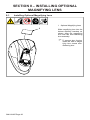
SECTION 8 – INSTALLING OPTIONAL MAGNIFYING LENS . . . . . . . . . . . . . . . . . . . . . . . . . . . . 20
8-1 Installing Optional Magnifying Lens . . . . . . . . . . . . . . . . . . . . . . . . . . . . . . . . . . . . . . . . . . 20
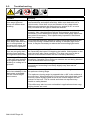
SECTION 9 – MAINTENANCE AND TROUBLESHOOTING. . . . . . . . . . . . . . . . . . . . . . . . . . . . . . 21
9-1 Maintenance And Storage . . . . . . . . . . . . . . . . . . . . . . . . . . . . . . . . . . . . . . . . . . . . . . . . . . 21
9-2 Troubleshooting. . . . . . . . . . . . . . . . . . . . . . . . . . . . . . . . . . . . . . . . . . . . . . . . . . . . . . . . . . . 22
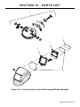
SECTION 10 – PARTS LIST . . . . . . . . . . . . . . . . . . . . . . . . . . . . . . . . . . . . . . . . . . . . . . . . . . . . . . . . . 23
SECTION 11 – LIMITED WARRANTY . . . . . . . . . . . . . . . . . . . . . . . . . . . . . . . . . . . . . . . . . . . . . . . . . 25

OM-281997 Page 1
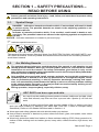
SECTION 1 – SAFETY PRECAUTIONS –
READ BEFORE USING
Protect yourself and others from injury—read, follow, and save these important safety
precautions and operating instructions.
1-1. Symbol Usage
DANGER! – Indicates a hazardous situation which, if not avoided, will result in death
or serious injury. The possible hazards are shown in the adjoining symbols or ex-
plained in the text.
Indicates a hazardous situation which, if not avoided, could result in death or seri-
ous injury. The possible hazards are shown in the adjoining symbols or explained in
the text.
NOTICE – Indicates statements not related to personal injury.
F
Indicates special instructions.
This group of symbols means Warning! Watch Out! ELECTRIC SHOCK, MOVING PARTS, and
HOT PARTS hazards. Consult symbols and related instructions below for necessary actions to
avoid these hazards.
1-2. Arc Welding Hazards
The symbols shown below are used throughout this manual to call attention to and
identify possible hazards. When you see the symbol, watch out, and follow the related
instructions to avoid the hazard. The safety information given below is only a sum-
mary of the more complete safety information found in the Principal Safety Standards.
Read and follow all Safety Standards.
Only qualified persons should install, operate, maintain, and repair this equipment. A
qualified person is defined as one who, by possession of a recognized degree, certifi-
cate, or professional standing, or who by extensive knowledge, training and experi-
ence, has successfully demonstrated the ability to solve or resolve problems relating
to the subject matter, the work, or the project and has received safety training to rec-
ognize and avoid the hazards involved.
During operation, keep everybody, especially children, away.
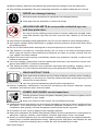
ARC RAYS can burn eyes and skin.
Arc rays from the welding process produce intense visible and invisible (ultra-
violet and infrared) rays that can burn eyes and skin. Sparks fly off from the
weld.
lWear a welding helmet fitted with a proper shade of filter to protect your face
and eyes when welding or watching (see ANSI Z49.1 and Z87.1 listed in Principal Safety
Standards). Refer to Lens Shade Selection table in Section 1-4.
lWear approved safety glasses with side shields under your helmet.
lUse protective screens or barriers to protect others from flash, glare, and sparks; warn others
not to watch the arc.
lWear body protection made from leather or flame-resistant clothing (FRC). Body protection in-
cludes oil-free clothing such as leather gloves, heavy shirt, cuffless trousers, high shoes, and
a cap.

OM-281997 Page 2
lBefore welding, adjust the auto-darkening lens sensitivity setting to meet the application.
lStop welding immediately if the auto-darkening lens does not darken when the arc is struck.
NOISE can damage hearing.
Noise from some processes or equipment can damage hearing.
lWear approved ear protection if noise level is high.
WELDING HELMETS do not provide unlimited eye, ear,
and face protection.
Arc rays from the welding process produce intense visible and invisible (ultra-
violet and infrared) rays that can burn eyes and skin. Sparks fly off from the
weld.
lUse helmet for welding/cutting applications only. Do not use helmet for laser welding/cutting.
lUse impact resistant safety spectacles or goggles and ear protection at all times when using
this welding helmet.
lDo not use this helmet while working with or around explosives or corrosive liquids.
lThis helmet is not rated for overhead welding. Do not weld in the direct overhead position
while using this helmet unless additional precautions are taken to protect yourself from arc
rays, spatter, and other hazards.
lInspect the auto-lens frequently. Immediately replace any scratched, cracked, or pitted cover
lenses or auto-lenses.
lLens and retention components must be installed as instructed in this manual to ensure com-
pliance with ANSI Z87.1 protection standards.
lThis helmet provides protection from projectiles associated with grinding, chipping, and re-
lated activities; it is not a hard hat and does not provide protection from falling objects.
READ INSTRUCTIONS.
lRead and follow all labels and the Owner’s Manual carefully before installing,
operating, or servicing unit. Read the safety information at the beginning of the
manual and in each section.
lUse only genuine replacement parts from the manufacturer.
lPerform installation, maintenance, and service according to the Owner’s Manuals, industry
standards, and national, state, and local codes.
FUMES AND GASES can be hazardous.
Welding produces fumes and gases. Breathing these fumes and gases can be
hazardous to your health.
lKeep your head out of the fumes. Do not breathe the fumes.
lVentilate the work area and/or use local forced ventilation at the arc to remove welding fumes
and gases. The recommended way to determine adequate ventilation is to sample for the
composition and quantity of fumes and gases to which personnel are exposed.
lIf ventilation is poor, wear an approved air-supplied respirator.
lRead and understand the Safety Data Sheets (SDSs) and the manufacturer’s instructions for
adhesives, coatings, cleaners, consumables, coolants, degreasers, fluxes, and metals.
lWork in a confined space only if it is well ventilated, or while wearing an air-supplied respirator.
Always have a trained watchperson nearby. Welding fumes and gases can displace air and
lower the oxygen level causing injury or death. Be sure the breathing air is safe.

OM-281997 Page 3
lDo not weld in locations near degreasing, cleaning, or spraying operations. The heat and rays
of the arc can react with vapors to form highly toxic and irritating gases.
lDo not weld on coated metals, such as galvanized, lead, or cadmium plated steel, unless the
coating is removed from the weld area, the area is well ventilated, and while wearing an air-
supplied respirator. The coatings and any metals containing these elements can give off toxic
fumes if welded.
1-3. California Proposition 65 Warnings
WARNING – Cancer and Reproductive Harm — www.P65Warnings.ca.gov.
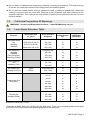
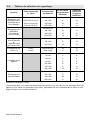
1-4. Lens Shade Selection Table
Process Electrode Size
in. (mm) Arc Current in
Amperes
Minimum Pro-
tective Shade
No.
Suggested
Shade No.
(Comfort)*
Shielded Metal
Arc
Welding
(SMAW)
Less than 3/32 (2.4) Less than 60 7 - -
3/32-5/32 (2.4-4.0) 60–160 8 10
5/32-1/4 (4.0-6.4) 160–250 10 12
More than 1/4 (6.4) 250–550 11 14
Gas Metal Arc
Welding
(GMAW)
Flux Cored Arc
Welding (FCAW)
Less than 60 7 - -
60–160 10 11
160–250 10 12
250–500 10 14
Gas Tungsten
Arc
Welding (TIG)
Less than 50 8 10
50–150 8 12
150–500 10 14
Air Carbon Arc
Cutting (CAC-A)
Light Less than 500 10 12
Heavy 500–1000 11 14
Plasma Arc Cut-
ting (PAC)
Less than 20 4 4
20–40 5 5
40–60 6 6
60–80 8 8
80–300 8 9
300–400 9 12
400–800 10 14
Plasma Arc
Welding (PAW)
Less than 20 6 6–8
20–100 8 10
100–400 10 12
400–800 11 14
Reference: ANSI Z49.1:2021
*Start with a shade that is too dark to see the weld zone. Then, go to a lighter shade which gives
a sufficient view of the weld zone without going below the minimum.

OM-281997 Page 4
1-5. Principal Safety Standards
Safety in Welding, Cutting, and Allied Processes, American Welding Society standard ANSI
Standard Z49.1. Website: http://www.aws.org.
Safe Practice For Occupational And Educational Eye And Face Protection, ANSI Standard Z87.1,
from American National Standards Institute. Website: www.ansi.org.
Safety in Welding, Cutting, and Allied Processes, CSA Standard W117.2 from Canadian Stand-
ards Association. Website: www.csagroup.org.
Industrial Head Protection, ANSI/ISEA Standard Z89.1 from American National Standards Insti-
tute. Website: www.ansi.org.
Australian National Work Health Safety Policy from Safe Work Australia. Website: www.safewor-
kaustralia.com.
Safety in Welding and Allied Processes, AS1674.1 and AS1674.2 part 1 and 2 from SAI Global.
Website: www.saiglobal.com.
Helmet 2022–01

OM-281997 Page 5
SECTION 2 – CONSIGNES DE SÉCURITÉ -
LIRE AVANT UTILISATION
Pour écarter les risques de blessure pour vous-même et pour autrui — lire, appliquer
et ranger en lieu sûr ces consignes relatives aux précautions de sécurité et au mode
opératoire.
2-1. Symboles utilisés
DANGER! – Indique une situation dangereuse qui si on l’évite pas peut donner la
mort ou des blessures graves. Les dangers possibles sont montrés par les symbo-
les joints ou sont expliqués dans le texte.
Indique une situation dangereuse qui si on l’évite pas peut donner la mort ou des
blessures graves. Les dangers possibles sont montrés par les symboles joints ou
sont expliqués dans le texte.
AVIS – Indique des déclarations pas en relation avec des blessures personnelles.
F
Indique des instructions spécifiques.
Ce groupe de symboles veut dire Avertissement! Attention! DANGER DE CHOC ELEC-
TRIQUE, PIECES EN MOUVEMENT, et PIECES CHAUDES. Reportez-vous aux symboles et
aux directives ci-dessous afin de connaître les mesures à prendre pour éviter tout danger.
2-2. Dangers concernant le soudage à l'arc
Les symboles représentés ci-dessous sont utilisés dans ce manuel pour attirer l’at-
tention et identifier les dangers possibles. En présence de ce symbole, prendre garde
et suivre les instructions afférentes pour éviter tout risque. Les consignes de sécurité
présentées ci-après ne font que résumer l’information contenue dans les Normes de
sécurité principales. Lire et suivre toutes les Normes de sécurité.
L’installation, l’utilisation, l’entretien et les réparations ne doivent être confiés qu’à
des personnes qualifiées. Une personne qualifiée est définie comme celle qui, par la
possession d’un diplôme reconnu, d’un certificat ou d’un statut professionnel, ou
qui, par une connaissance, une formation et une expérience approfondies, a démon-
tré avec succès sa capacité à résoudre les problèmes liés à la tâche, le travail ou le
projet et a reçu une formation en sécurité afin de reconnaître et d’éviter les risques
inhérents.
Au cours de l’utilisation, tenir toute personne à l’écart et plus particulièrement les
enfants.
LES RAYONS DE L'ARC peuvent provoquer des brûlures
des yeux et de la peau.
Le rayonnement de l'arc du procédé de soudage génère des rayons visibles et
invisibles intenses (ultraviolets et infrarouges) susceptibles de provoquer des
brûlures des yeux et de la peau. Des étincelles sont projetées pendant le
soudage.
lPorter un casque de soudage muni d'un écran de filtre approprié pour protéger votre visage et
vos yeux pendant le soudage ou pour regarder (voir ANSI Z49.1 et Z87.1 énumérés dans les
principales normes de sécurité). Voir le tableau Sélection du vignettage à la section 2-4.
lPorter des protections approuvées pour les oreilles si le niveau sonore est trop élevé.

OM-281997 Page 6
lAvoir recours à des écrans protecteurs ou à des rideaux pour protéger les autres contre les
rayonnements les éblouissements et les étincelles ; prévenir toute personne sur les lieux de
ne pas regarder l’arc.
lPorter une protection corporelle en cuir ou des vêtements ignifuges (FRC). La protection du
corps comporte des vêtements sans huile, comme des gants de cuir, une chemise solide, des
pantalons sans revers, des chaussures hautes et une casquette.
lAvant le soudage, ajuster le réglage de la sensibilité de la lentille auto-obscurcissante en fonc-
tion de l’application.
lArrêter immédiatement le soudage si la lentille auto-obscurcissante ne s’obscurcit pas lorsque
l’arc est frappé.
Le BRUIT peut endommager l’ouïe.
Le bruit des processus et des équipements peut affecter l’ouïe.
lPorter des protections approuvées pour les oreilles si le niveau sonore est trop
élevé.
Les CASQUES DE SOUDAGE ne fournissent pas une
protection illimitée des yeux, des oreilles et du visage.
Le rayonnement de l’arc du procédé de soudage génère des rayons visibles et
invisibles intenses (ultraviolets et infrarouges) susceptibles de provoquer des
brûlures dans les yeux et sur la peau. Des étincelles sont projetées pendant le
soudage.
lPorter un casque pour les applications de soudure/coupe seulement. Ne pas utiliser le casque
pour souder/découper au laser.
lPorter des lunettes de sécurité et des protecteurs antibruit résistants aux chocs en tout temps
pendant l’utilisation de ce casque de soudage.
lNe pas utiliser ce casque de soudage pendant la manutention ou le travail à proximité de liqui-
des explosifs ou corrosifs.
lCe casque n'est pas évalué pour le soudage à la verticale. Ne pas souder dans une position
directement à la verticale tout en utilisant ce casque à moins d'avoir pris des précautions sup-
plémentaires au préalable afin de se protéger contre les rayonnements de l'arc, des projec-
tions et d'autres risques.
lVérifier fréquemment l’état de la cellule à obscurcissement automatique. Remplacer immédia-
tement toute loupe ou cellule égratignée, fissurée ou piquée.
lLa lentille et les composants de rétention doivent être installés conformément aux instructions
de ce manuel pour garantir la conformité aux normes de protection ANSIZ87.1.
lCe casque offre une protection contre les projectiles associés au broyage, à l’écaillage et aux
activités; il ne s'agit pas d'un casque de sécurité, et celui-ci ne protège pas contre les chutes
d'objets.
LIRE LES INSTRUCTIONS.
lLire et appliquer les instructions sur les étiquettes et le Mode d’emploi avant
l’installation, l’utilisation ou l’entretien de l’appareil. Lire les informations de sé-
curité au début du manuel et dans chaque section.
lN’utiliser que des pièces de remplacement provenant du fabricant.
lEffectuer l’installation, l’entretien et toute intervention selon les manuels d’utilisateurs, les nor-
mes nationales, provinciales et de l’industrie, ainsi que les codes municipaux.

OM-281997 Page 7
LES FUMÉES ET LES GAZ peuvent être dangereux.
Le soudage génère des fumées et des gaz. Leur inhalation peut être dange-
reux pour votre santé.
lEloigner votre tête des fumées. Ne pas respirer les fumées.
lÀ l’intérieur, ventiler la zone et/ou utiliser une ventilation forcée au niveau de l’arc pour l’éva-
cuation des fumées et des gaz de soudage. Pour déterminer la bonne ventilation, il est recom-
mandé de procéder à un prélèvement pour la composition et la quantité de fumées et de gaz
auxquelles est exposé le personnel.
lSi la ventilation est médiocre, porter un respirateur anti-vapeurs approuvé.
lLire et comprendre les fiches de données de sécurité et les instructions du fabricant concer-
nant les adhésifs, les revêtements, les nettoyants, les consommables, les produits de refroi-
dissement, les dégraisseurs, les flux et les métaux.
lTravailler dans un espace fermé seulement s’il est bien ventilé ou en portant un respirateur à
alimentation d’air. Demander toujours à un surveillant dûment formé de se tenir à proximité.
Des fumées et des gaz de soudage peuvent déplacer l’air et abaisser le niveau d’oxygène pro-
voquant des blessures ou des accidents mortels. S’assurer que l’air de respiration ne présente
aucun danger.
lNe pas souder dans des endroits situés à proximité d’opérations de dégraissage, de net-
toyage ou de pulvérisation. La chaleur et les rayons de l’arc peuvent réagir en présence de va-
peurs et former des gaz hautement toxiques et irritants.
lNe pas souder des métaux munis d’un revêtement, tels que l’acier galvanisé, plaqué en plomb
ou au cadmium à moins que le revêtement n’ait été enlevé dans la zone de soudure, que l’en-
droit soit bien ventilé, et en portant un respirateur à alimentation d’air. Les revêtements et tous
les métaux renfermant ces éléments peuvent dégager des fumées toxiques en cas de
soudage.
2-3. Proposition californienne 65 Avertissements
AVERTISSEMENT – Cancer et troubles de la reproduction — www.P65Warnings.ca.
gov.

OM-281997 Page 8
2-4. Tableau de sélection du vignettage
Procédé Taille d'électrode
in. (mm) Courant d'arc
en ampères
N° de classe
de protection
minimum
Classe de
protection
suggérée
(Comfort)*
Soudage à l'arc
métallique avec
électrode enro-
bée (SMAW)
Moins de 3/32 (2,4) Moins de 60 7 - -
3/32-5/32 (2,4-4,0) 60–160 8 10
5/32-1/4 (4,0-6,4) 160–250 10 12
Plus de 1/4 (6,4) 250–550 11 14
Soudage à l'arc
MIG/MAG
Soudage fil
fourré (FCAW)
Moins de 60 7 - -
60–160 10 11
160–250 10 12
250–500 10 14
Soudage à l'arc
avec électrode
en
tungstène sous
gaz inerte (TIG)
Moins de 50 8 10
50–150 8 12
150–500 10 14
Coupage arc-air
(CAC-A)
Léger Moins de 500 10 12
Lourd 500–1000 11 14
Coupage à l'arc
plasma
Moins de 20 4 4
20–40 5 5
40–60 6 6
60–80 8 8
80–300 8 9
300–400 9 12
400–800 10 14
Soudage à l'arc
plasma (PAW)
Moins de 20 6 6–8
20–100 8 10
100–400 10 12
400–800 11 14
Référence: ANSI Z49.1:2021
*Commencer par une classe de protection trop foncée pour voir la zone de soudage. Ensuite,
passer à une classe de protection plus claire, permettant de voir suffisamment la zone de sou-
dage sans aller sous le seuil minimum.

OM-281997 Page 9
2-5. Principales normes de sécurité
Safety in Welding, Cutting, and Allied Processes, American Welding Society standard ANSI Stan-
dard Z49.1. Website: http://www.aws.org.
Safe Practice For Occupational And Educational Eye And Face Protection, ANSI Standard Z87.1,
from American National Standards Institute. Website: www.ansi.org.
Safety in Welding, Cutting, and Allied Processes, CSA Standard W117.2 from Canadian Stan-
dards Association. Website: www.csagroup.org.
Industrial Head Protection, ANSI/ISEA Standard Z89.1 from American National Standards Insti-
tute. Website: www.ansi.org.
Australian National Work Health Safety Policy from Safe Work Australia. Website: www.safewor-
kaustralia.com.
Safety in Welding and Allied Processes, AS1674.1 and AS1674.2 part 1 and 2 from SAI Global.
Website: www.saiglobal.com.
Helmet_fre 2022–01

OM-281997 Page 10
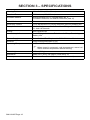
SECTION 3 – SPECIFICATIONS
Viewing Field 3.94 x 2.36 in. (100 x 60 mm)
Reaction Time 0.00004 sec (1/25,000 sec)
Available Shades Darkened State: No. 9–13/Light State: No. 3
Provides Continuous UV And IR Protection (DIN 15)
Grind Mode Yes
Sensitivity Control Lo-Hi Adjustment For Varying Ambient Light And Welding Arc
Delay Control Min-Max Adjustment Slows Lens Dark-To-Light State Between
0.1 And 0.9 Seconds
Power Auto-On/Auto-Off
Low Battery Indicator Red LED Light Illuminates To Indicate 2-3 Days Remaining
Battery Life
Power Supply Solar Cell And Two Replaceable CR2450 Lithium Batteries
Sensors Independent/Redundant (Four)
Operating Temperature 14°F to 149°F / -10°C to +65°C
F
When stored in extremely cold temperatures, warm hel-
met to ambient temperature before welding.
Total Weight 19.7 oz (560 g)
Standards ANSI Z87.1-2015, CE EN379, CSA Z94.3-15
Warranty Two Years From Date Of Purchase (see Section 11)

OM-281997 Page 11
SECTION 4 – OPERATION
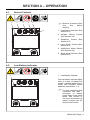
4-1. Helmet Controls
OM-281997 Page 2
SECTION 10 OPERATING INSTRUCTIONS
10-1. Helmet Controls 421 53
6
10-2. Low Battery Indicator
1
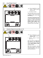
F
Remove protective films
from lens before
welding.
1 Low Battery Indicator (See
Section 4-2)
2 Variable Shade Control
(See Section 4-4)
3 Sensitivity Control (See
Section 4-5)
4 Lens Delay Control (See
Section 4-3)
5 Weld/Grind Mode Switch
(See Section 4-6)
6 Grind Mode Indicator (See
Section 4-6)
4-2. Low Battery Indicator
OM-281997 Page 2
SECTION 10 OPERATING INSTRUCTIONS
10-1. Helmet Controls 421 53
6
10-2. Low Battery Indicator
1
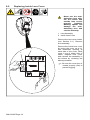
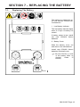
1 Low Battery Indicator
The low battery indicator lights
when 2-3 days of battery life
remain. If battery power is low,
install new CR2450 lithium
batteries (see Section 7-1).
F
The auto-darkening lens
consumes less than 1
microamp of battery
power when in the sleep
mode. See Section 4-
7for more information on
battery usage in the dif-
ferent power modes.

OM-281997 Page 12
4-3. Lens Delay Control
OM-281997 Page 3
10-3. Lens Delay Control
1
10-4. Variable Shade Control (No. 9–13)
1
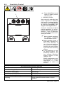
F
Place Weld/Grind mode
switch in Weld position
(Section 4-6).
1 Lens Delay Control
The lens delay control is used
to adjust the time for the lens
to switch to the clear state
after welding.
The delay is particularly useful
in eliminating bright after-rays
present in higher amperage
applications where the molten
puddle remains bright mo-
mentarily after welding. Lens
delay adjusts from min (0.1
second) to max (0.9 second).
4-4. Variable Shade Control (No. 9–13)
OM-281997 Page 3
10-3. Lens Delay Control
1
10-4. Variable Shade Control (No. 9–13)
1
F
Place Weld/Grind mode
switch in Weld position
(Section 4-6).
1 Variable Shade Control
(No. 9–13)
Use the control to adjust the
lens shade in the darkened
state. Use the table in Section
1-4 to select proper shade
control setting based on your
welding process.
Start at the highest setting
and adjust lighter to suit the
welding application and your
personal preference.

OM-281997 Page 13
4-5. Sensitivity Control
OM-281997 Page 4
10-5. Sensitivity Control
1
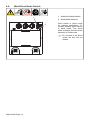
F
Place Weld/Grind mode
switch in Weld position
(Section 4-6).
1 Sensitivity Control
Use control to make the lens
more responsive to different
light levels in various welding
processes. Use a Mid-Range
or 50-70% sensitivity set-
ting for most applications.
It may be necessary to adjust
helmet sensitivity to accom-
modate different lighting con-
ditions or if lens is switching
on and off. Adjust helmet sen-
sitivity as follows:
F
Adjust helmet sensitivity
in lighting conditions
helmet will be used in.
lBefore welding (lens in
light state), face the hel-
met in the direction of
use. If the lens switches
on and off, it is being af-
fected by the surrounding
light. Decrease sensitivity
setting.
lIf lens switches on and
off during welding, the
sensitivity setting is too
low. Increase sensitivity
setting. Helmet is now
ready for use.
Slight readjustment may
be necessary for certain
applications or if lens
continues to switch on
and off.
Recommended Sensitivity Settings
Stick Electrode Mid-Range
Short Circuiting (MIG) Low/Mid-Range
Pulsed And Spray (MIG) Mid-Range
Gas Tungsten Arc (TIG) Mid/High-Range
Plasma Arc Cutting/Welding Low/Mid-Range
Grinding Place Weld/Grind Mode Switch In Grind
Position

OM-281997 Page 14
4-6. Weld/Grind Mode Switch
OM-281997 Page 5
10-6. Weld/Grind Mode Switch
1
2
10-7. Power Modes
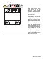
1 Weld/Grind Mode Switch
2 Grind Mode Indicator
Place switch in Grind mode
for grinding applications. To
resume welding, place switch
in Weld mode. The Grind
Mode indicator will blink when
helmet is in Grind mode.
F
Do not weld in the Grind
mode; the lens will not
darken.

OM-281997 Page 15
4-7. Power Modes
OM-281997 Page 5
10-6. Weld/Grind Mode Switch
1
2
10-7. Power Modes
The auto-darkening lens has
three power modes: sleep
(off), standby, and on. The
lens goes to sleep automati-
cally when ambient light is low
(less than 3 lux). The lens
consumes less than 1 micro-
amp of battery power when in
the sleep mode.
When ambient light exceeds
10 lux, the lens automatically
changes to the standby mode
and is ready for welding. The
lens relies on the solar cell for
power when in standby mode.
When welding begins, the
lens automatically turns on
(darkens). In most cases, the
solar cell provides enough
power to operate the lens dur-
ing welding. However, the lens
may use both solar and bat-
tery power when shade con-
trol is at a high setting.
The lens returns to standby
mode immediately after weld-
ing stops, and then enters
sleep mode if ambient lighting
is low (less than 3 lux).

OM-281997 Page 16
SECTION 5 – ADJUSTING HEADGEAR
5-1. Adjusting Headgear
OM-281997 Page 6
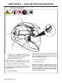
SECTION 11 ADJUSTING HEADGEAR
1
24
53
F
There are four headgear adjustments:
headgear top, tightness, angle adjust-
ment, and distance adjustment.
1 Headgear Top Adjustment
Adjusts headgear for proper depth on the
head to ensure correct balance and stability.
2 Headgear Tightness Adjustment
To adjust, turn the adjusting knob located on
the back of the headgear left or right to de-
sired tightness.
3 Angle Adjustment
Slots on the right side of the headband pro-
vide adjustment for the forward tilt of the hel-
met. To adjust, lift and reposition the control
arm to the desired position.
4 Distance Adjustment
5 Headgear Screw
Adjusts the distance between the face and
the lens. To adjust, loosen headgear screws
and slide headgear forward or backward to
one of the three slots on the slider. Tighten
screws. (Both sides must be equally posi-
tioned for proper vision.)

OM-281997 Page 17
SECTION 6 – REPLACING LENS COVERS
6-1. Replacing Outside Lens Cover
OM-281997 Page 7
SECTION 12 REPLACING THE LENS COVERS
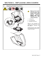
12-1. Replacing Outside Lens Cover
1
2
3
Never use the auto-
darkening lens with-
out the inside and
outside lens covers
properly installed.
Welding spatter will
damage the auto-
darkening lens and
void the warranty.
1 Locking Tab
2 Lens Assembly
3 Outside Lens Cover
Remove lens assembly by
sliding the locking tab to the
left. Remove cartridge and
lens cover.
Install new lens cover. Install
lens assembly and slide lock-
ing tab to the right.

OM-281997 Page 18
6-2. Replacing Inside Lens Cover
OM-281997 Page 8
12-2. Replacing Inside Lens Cover
1
2
Never use the auto-
darkening lens with-
out the inside and
outside lens covers
properly installed.
Welding spatter will
damage the auto-
darkening lens and
void the warranty.
1 Lens Assembly
2 Inside Lens Cover
Remove the lens cover holder
(see Section 6-1). Remove
lens assembly.
Remove the inside lens cover
by prying the cover up at ei-
ther thumbnail opening at
each side of the cover. Slide
cover it out of either side of
frame. Replace lens cover
and reinstall the assembly in
the helmet by reversing the
above procedure.
F
Be sure the cover lens is
seated properly (flat) to
prevent fogging.
La page est en cours de chargement...
La page est en cours de chargement...
La page est en cours de chargement...
La page est en cours de chargement...
La page est en cours de chargement...
La page est en cours de chargement...
La page est en cours de chargement...
La page est en cours de chargement...
-
 1
1
-
 2
2
-
 3
3
-
 4
4
-
 5
5
-
 6
6
-
 7
7
-
 8
8
-
 9
9
-
 10
10
-
 11
11
-
 12
12
-
 13
13
-
 14
14
-
 15
15
-
 16
16
-
 17
17
-
 18
18
-
 19
19
-
 20
20
-
 21
21
-
 22
22
-
 23
23
-
 24
24
-
 25
25
-
 26
26
-
 27
27
-
 28
28


HobartWelders HELMET INVENTOR AUTO-DARKENING Le manuel du propriétaire
- Catégorie
- Système de soudage
- Taper
- Le manuel du propriétaire
dans d''autres langues
Autres documents
-
Miller DIGITAL PERFORMANCE SERIES HELMETS Le manuel du propriétaire
-
-
-
Miller DIGITAL INFINITY SERIES AUTO-DARKENING HELMETS CL2 Le manuel du propriétaire
-
-
-
-
PROPOINT 8819864 Le manuel du propriétaire
-
 Thermal Arc 161 STL ® Inverter Arc Welder Manuel utilisateur
-
