Flex FX4221 Manuel utilisateur
- Catégorie
- Outils électroportatifs
- Taper
- Manuel utilisateur

Model:
Modelo:
Modèle:
OPERATOR’S MANUAL
MANUAL DEL OPERADOR
MANUEL DE L’UTILISATEUR
833-FLEX-496
(833-3539-496)
For English
Version
See page 2
◆
Version
française
Voir page 26
◆
Versión en
español
Ver la página 51
www.Registermyex.com
Contact Us /
Nous contacter /
Contáctenos
24V TRIM ROUTER
TOUPIE DE FINITION DES BORDS DE 24 V
FRESADORA RECORTADORA DE 24 V
FX4221

-2-
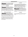
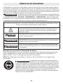
SAFETY SYMBOLS
The purpose of safety symbols is to attract your attention to possible dangers. The safety symbols
and the explanations with them deserve your careful attention and understanding. The symbol
warnings do not, by themselves, eliminate any danger. The instructions and warnings they give are
no substitutes for proper accident prevention measures.
WARNING Be sure to read and understand all safety instructions in this Operator’s Manual,
including all safety alert symbols such as “DANGER,” “WARNING,” and
“CAUTION” before using this tool. Failure to follow all instructions listed below may result in electric
shock, re, and/or serious personal injury.
The denitions below describe the level of severity for each signal word. Please read the manual and
pay attention to these symbols.
This is the safety alert symbol. It is used to alert you to potential personal
injury hazards. Obey all safety messages that follow this symbol to avoid
possible injury or death.
DANGER DANGER indicates a hazardous situation which, if not avoided, will result in
death or serious injury.
WARNING WARNING indicates a hazardous situation which, if not avoided, could result
in death or serious injury.
CAUTION CAUTION, used with the safety alert symbol, indicates a hazardous situation
which, if not avoided, will result in minor or moderate injury.
Damage Prevention and Information Messages
These inform the user of important information and/or instructions that could lead to equipment or
other property damage if they are not followed. Each message is preceded by the word “NOTICE”,
as in the example below:
NOTICE: Equipment and/or property damage may result if these instructions are not followed.
WARNING The operation of any power tools can result in foreign
objects being thrown into your eyes, which can result in
severe eye damage. Before beginning power tool operation, always wear
safety goggles or safety glasses with side shields and a full face shield when
needed. We recommend a Wide Vision Safety Mask for use over eyeglasses
or standard safety glasses with side shields. Always use eye protection which
is marked to comply with ANSI Z87.1.

-3-
GENERAL POWER TOOL SAFETY WARNINGS
WARNING Read all safety warnings, instructions, illustrations and specications
provided with this power tool. Failure to follow all instructions listed below may
result in electric shock, re and/or serious injury.
SAVE ALL WARNINGS AND INSTRUCTIONS FOR FUTURE REFERENCE.
The term “power tool” in the warnings refers to your mains-operated (corded) power tool or battery
operated (cordless) power tool.
Work area safety
Keep work area clean and well lit. Cluttered
or dark areas invite accidents.
Do not operate power tools in explosive
atmospheres, such as in the presence of
ammable liquids, gases or dust. Power
tools create sparks which may ignite the dust or
fumes.
Keep children and bystanders away while
operating a power tool. Distractions can cause
you to lose control.
Electrical safety
Power tool plugs must match the outlet.
Never modify the plug in any way. Do
not use any adapter plugs with earthed
(grounded) power tools. Unmodied plugs
and matching outlets will reduce risk of electric
shock.
Avoid body contact with earthed or
grounded surfaces, such as pipes, radiators,
ranges and refrigerators. There is an
increased risk of electric shock if your body is
earthed or grounded.
Do not expose power tools to rain or wet
conditions. Water entering a power tool will
increase the risk of electric shock.
Do not abuse the cord. Never use the cord
for carrying, pulling or unplugging the
power tool. Keep cord away from heat, oil,
sharp edges or moving parts. Damaged or
entangled cords increase the risk of electric
shock.
When operating a power tool outdoors, use
an extension cord suitable for outdoor use.
Use of a cord suitable for outdoor use reduces
the risk of electric shock.
If operating a power tool in a damp location
is unavoidable, use a ground fault circuit
interrupter (GFCI) protected supply. Use of a
GFCI reduces the risk of electric shock.
Personal safety
Stay alert, watch what you are doing and
use common sense when operating a power
tool. Do not use a power tool while you are
tired or under the inuence of drugs, alcohol
or medication. A moment of inattention while
operating power tools may result in serious
personal injury.
Use personal protective equipment. Always
wear eye protection. Protective equipment such
as a dust mask, non-skid safety shoes, hard
hat or hearing protection used for appropriate
conditions will reduce personal injuries.
Prevent unintentional starting. Ensure
the switch is in the off-position before
connecting to power source and/or battery
pack, picking up or carrying the tool.
Carrying power tools with your nger on the
switch or energizing power tools that have the
switch on invites accidents.
Remove any adjusting key or wrench before
turning the power tool on. A wrench or a key
left attached to a rotating part of the power tool
may result in personal injury.
Do not overreach. Keep proper footing
and balance at all times. This enables
better control of the power tool in unexpected
situations.
Dress properly. Do not wear loose clothing
or jewelry. Keep your hair and clothing away
from moving parts. Loose clothes, jewelry or
long hair can be caught in moving parts.
If devices are provided for the connection
of dust extraction and collection facilities,
ensure these are connected and properly
used. Use of dust collection can reduce
dust-related hazards.
Do not let familiarity gained from frequent
use of tools allow you to become
complacent and ignore tool safety
principles. A careless action can cause severe
injury within a fraction of a second.

-4-
Power tool use and care
Do not force the power tool. Use the correct
power tool for your application. The correct
power tool will do the job better and safer at the
rate for which it was designed.
Do not use the power tool if the switch
does not turn it on and off. Any power tool
that cannot be controlled with the switch is
dangerous and must be repaired.
Disconnect the plug from the power
source and/or remove the battery pack,
if detachable, from the power tool before
making any adjustments, changing
accessories, or storing power tools. Such
preventive safety measures reduce the risk of
starting the power tool accidentally.
Store idle power tools out of the reach of
children and do not allow persons unfamiliar
with the power tool or these instructions
to operate the power tool. Power tools are
dangerous in the hands of untrained users.
Maintain power tools and accessories.
Check for misalignment or binding of
moving parts, breakage of parts and any
other condition that may affect the power
tool’s operation. If damaged, have the power
tool repaired before use. Many accidents are
caused by poorly maintained power tools.
Keep cutting tools sharp and clean. Properly
maintained cutting tools with sharp cutting
edges are less likely to bind and are easier to
control.
Use the power tool, accessories and
tool bits etc. in accordance with these
instructions, taking into account the working
conditions and the work to be performed.
Use of the power tool for operations different
from those intended could result in a hazardous
situation.
Keep handles and grasping surfaces dry,
clean and free from oil and grease. Slippery
handles and grasping surfaces do not allow
for safe handling and control of the tool in
unexpected situations.
Battery tool use and care
Recharge only with the charger specied by
the manufacturer. A charger that is suitable for
one type of battery pack may create a risk of re
when used with another battery pack.
Use power tools only with specically
designated battery packs. Use of any other
battery packs may create a risk of injury and
re.
When battery pack is not in use, keep it
away from other metal objects, like paper
clips, coins, keys, nails, screws or other
small metal objects, that can make a
connection from one terminal to another.
Shorting the battery terminals together may
cause burns or a re.
Under abusive conditions, liquid may be
ejected from the battery; avoid contact.
If contact accidentally occurs, ush with
water. If liquid contacts eyes, additionally
seek medical help. Liquid ejected from the
battery may cause irritation or burns.
Do not use a battery pack or tool that is
damaged or modied. Damaged or modied
batteries may exhibit unpredictable behavior
resulting in re, explosion or risk of injury.
Do not expose a battery pack or tool to re
or excessive temperature. Exposure to re or
temperature above 265 °F (130 °C) may cause
explosion.
Follow all charging instructions and do
not charge the battery pack or tool outside
the temperature range specied in the
instructions. Charging improperly or at
temperatures outside the specied range may
damage the battery and increase the risk of re.
Service
Have your power tool serviced by a
qualied repair person using only identical
replacement parts. This will ensure that the
safety of the power tool is maintained.
Never service damaged battery packs.
Service of battery packs should only be
performed by the manufacturer or authorized
service providers.

-5-
SAFETY WARNINGS FOR TRIM ROUTER
• Use clamps or another practical way to
secure and support the workpiece to a
stable platform. Holding the work by your
hand or against the body leaves it unstable
and may lead to loss of control.
• Never operate cutter bits at speeds that are
higher than their maximum rated speed.
Cutter bits running faster than their rated
speed can break and y apart.
• Never use cutter bits with a diameter
exceeding the maximum diameter specied
in the technical data section.
• If cutting into existing walls or other blind
areas where electrical wiring may exist is
unavoidable, disconnect all fuses or circuit
breakers feeding this worksite.
• Wear a dust mask specically designed
for protection against lead paint dust and
fumes and ensure that persons within or
entering the work area are also protected.
• Wear ear protection. Exposure to noise can
cause hearing loss.
• Always use safety glasses. Also use a
face or dust mask if the cutting operation is
dusty. Everyday eyeglasses only have impact
resistant lenses. They are not safety glasses.
• Never lay the tool down until the motor has
come to a complete standstill. The spinning
cutter bit can grab the surface and pull the tool
out of your control.

-6-
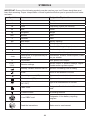
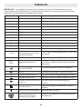
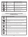
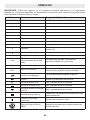
SYMBOLS
IMPORTANT: Some of the following symbols may be used on your tool. Please study them and
learn their meaning. Proper interpretation of these symbols will allow you to operate the tool better
and safer.
Symbol Name Designation/Explanation
V Volts Voltage
A Amperes Current
Hz Hertz Frequency (cycles per second)
W Watt Power
kg Kilograms Weight
min Minutes Time
s Seconds Time
Wh Watt-hours Battery capacity
Ah Ampere-hours Battery capacity
ø Diameter Size of drill bits, grinding wheels, etc.
n0No load speed Rotational speed, at no load
n Rated speed Maximum attainable speed
…/min Revolutions or reciprocations per
minute (rpm)
Revolutions, strokes, surface speed, orbits,
etc. per minute
O Off position Zero speed, zero torque...
1,2,3,…
I,II,III, Selector settings Speed, torque, or position settings. Higher
number means greater speed
Innitely variable selector with off Speed is increasing from 0 setting
Arrow Action in the direction of arrow
Alternating current (AC) Type or a characteristic of current
Direct current (DC) Type or a characteristic of current
Alternating or direct current
(AC / DC) Type or a characteristic of current
Class II tool Designates Double Insulated Construction
tools.
Protective earth Grounding terminal
Li-ion RBRC seal Designates Li-ion battery recycling
program
Read the instructions Alerts user to read manual

-7-
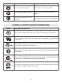
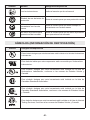
Symbol Name Designation/Explanation
Wear eye protection symbol Alerts user to wear eye protection
Always operate with two hands Alerts user to always operate with two
hands
Do not use the guard for cut-off
operations Do not use the guard for cut-off operations
SYMBOLS (CERTIFICATION INFORMATION)
Symbol Designation/Explanation
This symbol designates that this tool is listed by Underwriters Laboratories.
This symbol designates that this component is recognized by Underwriters
Laboratories.
This symbol designates that this tool is listed by Underwriters Laboratories, to
United States and Canadian Standards.
This symbol designates that this tool is listed by the Canadian Standards
Association.
This symbol designates that this tool is listed by the Canadian Standards
Association, to United States and Canadian Standards.
This symbol designates that this tool is listed by the Intertek Testing Services,
to United States and Canadian Standards.

-8-
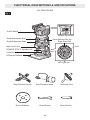
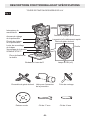
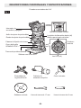
FUNCTIONAL DESCRIPTIONS & SPECIFICATIONS
24V TRIM ROUTER
Fig. 1
Edge Guide Assembly
Round Subbase
Dust Extraction Hood
17mm Wrench
Centering Cone
12mm Wrench
LED Light (x2)
Edge Guide Slot
Variable Speed Dial
On/Off Switch
Depth Adjustment Ring
Depth Adjustment Scale
Base Lock Lever
SPINDLE STOP™ Spindle Lock
Collet Nut
D-Shaped Subbase
Quick Release Tab (x2)
Collet

-9-
Model No. FX4221
Rated Voltage 24 V d.c.
Collet Capacity 1/4”
No-load Speed Up to 31000 /min
Recommended
operating
temperature
-4 – 104 °F (-20 – 40 oC)
Recommended
storage
temperature
122 °F (< 50 oC)

-10-
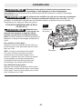
TO ATTACH/DETACH BATTERY PACK
(FIG. 2)
WARNING Make sure the on/off
switch is not pressed
when attaching or detaching the battery
pack. Such preventive safety measures reduce
the risk of starting the tool accidentally.
To attach the battery pack:
Align the raised rib on the battery pack with the
grooves in the tool, and then slide the battery
pack onto the tool.
NOTICE: When placing the battery pack
onto the tool, be sure that the raised rib
on the battery pack aligns with the groove
inside the tool and that the latches snap into
place properly. Improper attachment of the
battery pack can cause damage to internal
components.
To detach the battery pack:
Depress the battery-release button located
on the front of the battery pack, to release the
battery pack. Pull the battery pack out and
remove it from the tool.
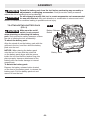
ASSEMBLY
WARNING Detach the battery pack from the tool before performing any assembly or
adjustments, or changing accessories. Such preventive safety measures
reduce the risk of starting the tool accidentally.
WARNING Do not attempt to modify this tool or create accessories not recommended
for use with this tool. Any such alteration or modication is misuse and could
result in a hazardous condition leading to possible serious injury.
Fig. 2
Battery Pack
Battery-Release
Button

-11-
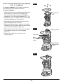
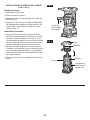
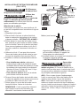
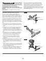
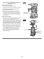
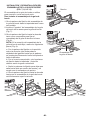
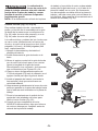
INSTALLING AND REMOVING THE BASE
(FIG. 3 AND 4)
To remove the base
1. Detach the battery pack.
2. Place the tool upside down.
3. Open the lock lever on the base unit (Fig. 3).
4. Depress both quick release tabs on the motor
unit with one hand. With the other hand, pull
the base unit from the motor unit (Fig. 4).
To install the base
1. Align the vertical slot on the motor unit with
the pegs on the inside of the base unit as
shown in Fig. 4. It is recommended to make
the spindle lock face the dust outlet for easy
operation on the spindle lock.
2. Lower the base unit onto the motor unit. Push
the base unit down until you hear a “click”,
which means the base unit is mounted onto
the motor unit properly.
3. Close the lock lever on the base unit.
Fig. 3
Base Lock Lever
Fig. 4 Base
Pegs
Motor
Slot
Quick
Release
Tab (x2)

-12-
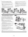
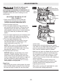
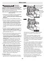
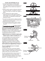
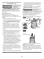
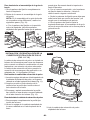
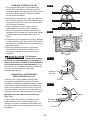
INSTALLING AND REMOVING BITS
(FIG. 5, AND 6)
WARNING Do not use bits with
damaged shanks.
WARNING Use protective gloves
when removing the bit
from the tool, or rst allow the bit to cool
down. The bit may be hot after prolonged use.
Select the bit
This router is shipped with a 1/4” collet that
accepts cutter bits with 1/4” shanks.
1. Detach the battery pack.
2. Place the tool upside down and remove
the base unit following above section “TO
REMOVE THE BASE”.
3. Slide the spindle lock down, until it audibly
clicks, to lock the spindle shaft in place.
Alternatively, you can use the 12 mm wrench
to hold the spindle securely.
4. Use the 17 mm wrench to turn the collet nut
counterclockwise (Fig. 5).
5. Install or remove the bit/collet as follows:
• To install a bit, clean and insert the
round shank of the desired router bit into
the collet so that the cutting surfaces are
approximately 1/8” (3.2 mm) to 1/4” (6.4
mm) away from the face of the collet (Fig. 6).
• To remove the bit, pull the bit out of the
collet.
6. Turn the collet nut clockwise to tighten the bit
using the 17 mm.
7. Slide the spindle lock up to release the
spindle shaft.
NOTE: The tool could be started only when
the spindle lock is released. The LED lights
will ash to signal that the spindle is locked
when the On/Off switch is pressed.
8. Install the base following above section “TO
INSTALL THE BASE”.
Fig. 5
17mm
Wrench
12mm Wrench
SPINDLE STOP™
Spindle Lock
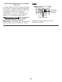
Fig. 6
Bit (not provided)
WARNING Tighten the collet nut
securely to prevent the
cutter bit from slipping. If the collet nut is not
tightened securely, the cutter bit may detach
during use, causing serious personal injury.
NOTICE: To prevent damage to tool, do
not tighten the collet nut without a cutter bit
installed.
NOTICE: To ensure proper gripping of the cutter
bit shank and minimize run-out, the shank of the
cutter bit must be inserted at least 5/8” (16 mm)
into the collet.

-13-
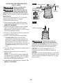
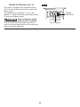
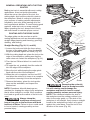
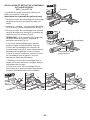
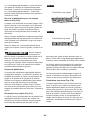
INSTALLING AND REMOVING THE EDGE
GUIDE ASSEMBLY (FIG. 7, 8, 9, AND 10)
The edge guide assembly is used to trim or cut
a straight edge.
To install the edge guide assembly
1. Turn the lock lever of the edge guide
assembly to the left as far as it will go.
2. Insert the "hook" of the edge guide assembly
into the edge guide slot (Fig. 7).
3. Turn the lock lever to the right as far as it will
go to secure the edge guide assembly to the
base (Fig. 8).
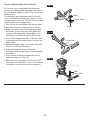
NOTE:
If the connection of edge guide
assembly is loose, perform the following steps
(Fig. 9):
a. With the lock lever in the right-most
position, pull the lock lever away from the
hook until the lever can freely turn left or right.
b. With the spring compressed, rotate the
lock lever to the left. You shouldn't feel any
resistance!
c. Release the lock lever to let it spring back
and engage with the tightening mechanism.
d. Turn the lock lever to the right until the
edge guide assembly is securely attached to
the base.
Fig. 7
Hook
Fig. 8
Lock Lever
Edge Guide
Assembly
ab
c
d
Fig. 9

-14-
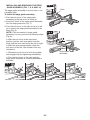
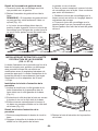
To remove the edge guide assembly
1. Turn the lock lever all the way to the left.
2. Remove the edge guide assembly from the
slot.
NOTE: If the edge guide assembly could
not be removed easily, perform the following
steps (Fig. 10):
a. With the lock lever in the left-most position,
pull the lock lever away from the hook until
the lever can freely turn left or right.
b. With the spring compressed, rotate the
lock lever to the right. You shouldn't feel any
resistance!
c. Release the lock lever to let it spring back
and engage with the tightening mechanism.
d. Turn the lock lever to the left until the edge
guide assembly can be removed from the
edge guide slot.
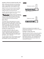
INSTALLING AND REMOVING THE DUST
EXTRACTION HOOD (FIG. 11 AND 12)
The dust extraction hood attaches to the
router base for dust free routing when used in
combination with a suitable vacuum cleaner/
dust extractor. The dust extraction hood allows
connection of a 1-1/4” (32 mm) vacuum hose or
adaptor.
To install the dust extraction hood
1. Insert the peg on the left side of the dust
extraction hood into the slot on the left side of
the base (Fig. 11).
2. Snap the right side of the hood with the screw
knob onto the right side of the base.
3. Manually thread and tighten the screw knob
into a threaded opening on the right side of
the base (Fig. 12).
To remove the dust extraction hood
1. Fully unscrew the screw knob from the base.
2. Release the peg of the hood from the slot on
the left side of the base.
3. Pull the dust extraction hood away from the
base.
Fig. 12
Screw Knob
Fig. 11
Peg
Slot
a
bc
d
Fig. 10

-15-
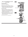
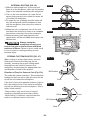
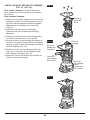
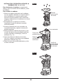
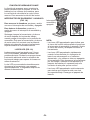
INSTALLING AND REMOVING THE SUBBASE
(FIG. 13, 14, AND 15)
To remove subbase, just loosen and remove
the subbase screws and the subbase.
To install subbase
1. Align the holes on the subbase with the holes
at the bottom of the tool. The edge guide
slot can be used as a reference during the
alignment of the D-shaped subbase (Fig. 13).
2. Thread in but do not tighten the screws. Make
sure the subbase can move freely.
3. Insert the pin of the centering cone into the
collet and tighten the collet nut.
4. Open the base lock lever and turn the depth
adjustment ring until the centering cone stops
and centers the subbase (Fig. 14).
5. Close the base lock lever (Fig. 14) and tighten
the subbase screws to x the subbase
(Fig. 15).
6. Loosen the collet nut and remove the
centering cone.
BRUSHLESS
Fig. 15
Fig. 13
Edge Guide
Slot
BRUSHLESS
Fig. 14 Centering Cone
Base Depth
Adjustment
Ring
Base
Lock
Lever
Collet Nut

-16-
TEMPLATE GUIDES (NOT PROVIDED)
The round subbase will accept universal
template guides. Use only a maximum 1-3/16"
(30.5 mm) template guide with this tool.
To use a template guide:
1. Center the round subbase following the
instruction in above section “TO INSTALL
SUBBASE”.
2. Insert the template guide into the center hole
of the round subbase and secure according to
the template guide instructions.
NOTICE: The D-shaped subbase does not
accommodate template guides and is designed
to accommodate bits up to 1-1/2” (38 mm) in
diameter.

-17-
ADJUSTMENTS
WARNING Detach the battery pack
from the tool before
performing any assembly or adjustments, or
changing accessories. Such preventive safety
measures reduce the risk of starting the tool
accidentally.
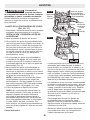
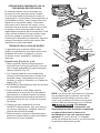
ADJUSTING THE DEPTH OF CUT
(FIG. 16 AND 17)
1. Select and install the desired cutter bit
following the instructions in the section
“INSTALLING AND REMOVING BITS”.
2. Open the base lock lever.
3. Turn the depth adjustment ring until the bit
just touches the work piece. Turning the ring
clockwise raises the cutter bit (reduces the
cutting depth) while turning it counterclockwise
lowers the cutter bit (increases the cutting
depth).
4. Turn the depth adjustment scale clockwise until
the zero mark on the scale lines up with the
pointer on the depth adjustment ring (Fig. 16).
5. Turn the depth adjustment ring
counterclockwise until the pointer lines up
with desired depth of cut marking on the
depth adjustment scale (Fig. 17).
NOTE: Each mark on the depth adjustment
scale represents a depth change of 1/64”
(0.4 mm) and one full (360°) turn of the ring
changes the depth by 1/2” (12.7 mm).
6. Close the base lock lever.
NOTICE: Making a single deep cut is never
advisable. Smaller diameter cutter bits are
easily broken by too much lateral thrust and
torque. Larger cutter bits will cause a rough cut
and will be difcult to guide and control. For
these reasons, do not exceed 1/8” (3.2 mm)
cutting depth in a single pass.
Deep Cuts
• Determining the proper cutting depth (for each
pass) should always be based on the material,
the size and type of cutter bit, and the power
of the motor.
• Always make several progressively deeper
cuts. Start at one depth and then make several
passes, increasing the cutting depth each
time, until the desired depth is reached.
• Making a cut that is too deep will put stress on
the motor and the cutter bit, and it may burn
the workpiece and dull the cutter bit. It could
also “grab” too much of the workpiece and
result in loss of control of the router, causing a
serious accident.
• To be certain that the depth settings are
as desired, always make test cuts in scrap
material similar to the workpiece before
beginning the nal cut.
• Remember, knowing the right depth for each
cut comes with routing experience.
2
1
Fig. 17
Fig. 16
Pointer
Zero
Mark
Depth
Adjustment Ring
Depth Adjustment
Scale
Base Lock
Lever
Bit
Workpiece

-18-
VARIABLE SPEED DIAL (FIG. 18)
The router is equipped with a variable speed
dial. Turn the variable speed dial to control the
router speed.
The speed dial is numbered “1” to “6”, with
position “1” being the lowest speed and position
“6” being the highest speed.
WARNING Never change the speed
while the tool is running.
Failure to obey this could make you lose of
control of the tool and result in serious personal
injury and property damage.
Fig. 18
Current Speed
Variable
Speed Dial

-19-
SOFT START FEATURE
The soft-start feature minimizes torque twist,
which is customary in router motors, by limiting
the speed at which the motor starts. This
increases the life of the motor.
ON/OFF SWITCH (FIG. 19)
To start the router, depress and release the
on/off switch once.
To stop the router, depress and release the on/
off switch again.
Always hold the tool and cutter bit away from
the workpiece when turning on the switch. Only
allow the tool and cutter bit to come into contact
with the workpiece after it has reached full
speed.
LED LIGHTS (FIG. 19)
The tool is equipped with 2 built-in LED
lights located around the collet. They provide
additional light on the surface of the workpiece
for operation in lower-light areas.
The LED light will automatically turn on when
starting the tool, and will turn off approximately
10 seconds after the tool is stopped.
NOTE:
• The LED lights will ash to signal that the
spindle lock is engaged when the On/Off
switch is pressed. Release the spindle lock
and start the tool again.
• The LED lights will rapidly ash when the tool
and/or battery pack becomes overloaded or
too hot, and the internal sensors will turn the
tool off. Rest the tool for a while or place the
tool and battery pack separately under air ow
to cool them.
• The LED lights will ash more slowly to
indicate that the battery is at low-battery
capacity. Recharge the battery pack.
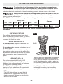
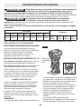
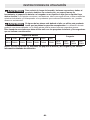
OPERATION INSTRUCTIONS
WARNING To reduce the risk of re, personal injury, and product damage due to a
short circuit, never immerse your tool, battery pack or charger in uid or
allow a uid to ow inside them. Corrosive or conductive uids, such as seawater, certain
industrial chemicals, and bleach or bleach-containing products, etc. can cause a short circuit.
WARNING If any parts are damaged or missing, do not operate this product until the
parts are replaced. Use of this product with damaged or missing parts could
result in serious personal injury.
This TRIM Router must be used only with the battery packs and chargers listed below:
Battery Pack Charger
2.5Ah 3.5Ah 5.0Ah 6Ah 8.0Ah 10Ah 12Ah
FX0111 FX0321 FX0121 FX0331 FX0221 FX0341 FX0231 FLEX
FX0411
FLEX
FX0421
FLEX
FX0431
FLEX
FX0451
NOTICE: Please refer to the battery pack and charger manuals for detailed operating
information.
BRUSHLESS
Fig. 19
LED Lights
On/Off
Switch

-20-
GENERAL OPERATIONS WITH THE TRIM
ROUTER
Making test cuts is essential with most routing
applications. A test cut yields information
about the set-up, the speed of the tool, the
cutting depth, and how the cutter bit reacts to
the workpiece. Much of routing is a trial-and-
error process of making various adjustments,
followed by test cuts, while learning all of the
tool’s operational abilities. To avoid ruining good
material, make test cuts on scrap material.
When operating the tool, always hold it rmly
with both hands to maintain proper control.
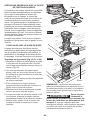
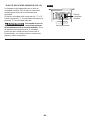
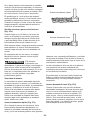
ROUTING WITH THE EDGE GUIDE
The edge guide can be used as an aid in
routing applications such as decorative edging,
straight-edge planning and trimming, grooving,
dadoing, and slotting.
Straight Routing (Fig. 20, 21, and 22)
1. Loosen the knob and slide the fence along
the arm of the edge guide. Once the desired
length is reached, tighten the knob (Fig. 20).
2. With the cutting depth set, place the tool on the
edge of the workpiece, making sure that the
cutter does not contact the workpiece (Fig. 21).
3. Turn the tool ON and allow it to reach its full
speed.
4. To begin the cut, gradually feed the cutter bit
into the edge of the workpiece.
5. Move the tool while keeping the edge guide
ush with the side of the workpiece.
6. When the cut is complete, turn the tool OFF
and allow the cutter bit to come to a complete
stop before removing it from the workpiece.
7. Remove the battery, place the tool upside-
down on the worktable, and inspect the
nished cut.
NOTE: Roundover bits with bearings are
excellent for shaping the edge of any workpiece
that is either straight or curved, if the curvature
is at least as great as the radius of the bit to be
used.
WARNING Always clamp the
workpiece securely and
keep a rm grip on the tool base with both
hands at all times. Failure to do so could result
in loss of control, causing possibly serious
personal injury.
WARNING Removing the cutter bit
from the workpiece while
it is still rotating could damage the
workpiece and result in loss of control,
causing possibly serious personal injury.
NOTE: If the distance between the side of
the workpiece and the cutting position is too
wide for the edge guide, or if the side of the
workpiece is not straight, rmly clamp a straight
board to the workpiece and use it as a guide
against the router base. Feed the tool in the
direction of the arrow (Fig. 22).
BRUSHLESS
Fig. 21
Edge Guide
Assembly
BRUSHLESS
Guide
Fig. 22
Fig. 20
Knob
Arm
Fence
La page est en cours de chargement...
La page est en cours de chargement...
La page est en cours de chargement...
La page est en cours de chargement...
La page est en cours de chargement...
La page est en cours de chargement...
La page est en cours de chargement...
La page est en cours de chargement...
La page est en cours de chargement...
La page est en cours de chargement...
La page est en cours de chargement...
La page est en cours de chargement...
La page est en cours de chargement...
La page est en cours de chargement...
La page est en cours de chargement...
La page est en cours de chargement...
La page est en cours de chargement...
La page est en cours de chargement...
La page est en cours de chargement...
La page est en cours de chargement...
La page est en cours de chargement...
La page est en cours de chargement...
La page est en cours de chargement...
La page est en cours de chargement...
La page est en cours de chargement...
La page est en cours de chargement...
La page est en cours de chargement...
La page est en cours de chargement...
La page est en cours de chargement...
La page est en cours de chargement...
La page est en cours de chargement...
La page est en cours de chargement...
La page est en cours de chargement...
La page est en cours de chargement...
La page est en cours de chargement...
La page est en cours de chargement...
La page est en cours de chargement...
La page est en cours de chargement...
La page est en cours de chargement...
La page est en cours de chargement...
La page est en cours de chargement...
La page est en cours de chargement...
La page est en cours de chargement...
La page est en cours de chargement...
La page est en cours de chargement...
La page est en cours de chargement...
La page est en cours de chargement...
La page est en cours de chargement...
La page est en cours de chargement...
La page est en cours de chargement...
La page est en cours de chargement...
La page est en cours de chargement...
La page est en cours de chargement...
La page est en cours de chargement...
La page est en cours de chargement...
La page est en cours de chargement...
-
 1
1
-
 2
2
-
 3
3
-
 4
4
-
 5
5
-
 6
6
-
 7
7
-
 8
8
-
 9
9
-
 10
10
-
 11
11
-
 12
12
-
 13
13
-
 14
14
-
 15
15
-
 16
16
-
 17
17
-
 18
18
-
 19
19
-
 20
20
-
 21
21
-
 22
22
-
 23
23
-
 24
24
-
 25
25
-
 26
26
-
 27
27
-
 28
28
-
 29
29
-
 30
30
-
 31
31
-
 32
32
-
 33
33
-
 34
34
-
 35
35
-
 36
36
-
 37
37
-
 38
38
-
 39
39
-
 40
40
-
 41
41
-
 42
42
-
 43
43
-
 44
44
-
 45
45
-
 46
46
-
 47
47
-
 48
48
-
 49
49
-
 50
50
-
 51
51
-
 52
52
-
 53
53
-
 54
54
-
 55
55
-
 56
56
-
 57
57
-
 58
58
-
 59
59
-
 60
60
-
 61
61
-
 62
62
-
 63
63
-
 64
64
-
 65
65
-
 66
66
-
 67
67
-
 68
68
-
 69
69
-
 70
70
-
 71
71
-
 72
72
-
 73
73
-
 74
74
-
 75
75
-
 76
76


Flex FX4221 Manuel utilisateur
- Catégorie
- Outils électroportatifs
- Taper
- Manuel utilisateur
dans d''autres langues
- English: Flex FX4221 User manual
- español: Flex FX4221 Manual de usuario
Documents connexes
Autres documents
-
Bosch GKF125CEK Manuel utilisateur
-
-
Bosch Power Tools PR10E Manuel utilisateur
-
-
-
-
-
Bosch Power Tools 1617EVS Manuel utilisateur
-
Bosch GCU18V-30 Le manuel du propriétaire