ROBBE AIRBULL 3129 Assembly And Operating Instructions Manual
- Catégorie
- Jouets télécommandés
- Taper
- Assembly And Operating Instructions Manual
La page est en cours de chargement...

Airbull
3
Bauanleitung, Assembly instructions, Notice de montage
No.
3129
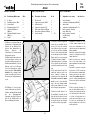
Technische Daten
Spannweite: ca. 1300 mm
Gesamtlänge: ca. 580 mm
Gesamtflächeninhalt: ca. 31,5 dm
2
Fluggewicht: ab 1100 g
Gesamtflächenbelastung: ab 35 g/dm
2
Antrieb: Elektro-Druckantrieb
Nicht enthaltenes Zubehör siehe Beilageblatt
Werkzeuge siehe robbe Hauptkatalog
Allgemeine Hinweise für den Bauablauf
Die Numerierung entspricht im wesentlichen der
Reihenfolge des Bauablaufs, wobei die Nummer vor dem
Punkt die Baustufe, die Nummer hinter dem Punkt das
betreffende Bauteil angibt.
Verschaffen Sie sich in Verbindung mit den Abbildungen und
Kurztexten, sowie der Stückliste einen Überblick über die
jeweiligen Bauschritte.
Richtungsangaben, wie z. Bsp. „rechts“ sind in Flugrichtung
zu sehen.
Besondere Hinweise zu dem Werkstoff “Arcel”
Der Airbull ist aus dem schlagzähen Formschaum “Arcel”
gefertigt. Dies bedeutet keine größeren Probleme beim Bau
des Modells, jedoch müssen beim Kleben und der
Oberflächenbehandlung einige werkstofftypische
Eigenheiten beachtet werden.
Verklebungen
Klebearbeiten an Arcel-Formschaumteilen nur mit Robbe-
Speed-Sekundenkleber T
yp 2 ausführ
en. Um die V
erklebung
zu beschleunigen empfiehlt sich die V
erwendung von
Aktivatorspray.
Specification
Wingspan: approx. 1300 mm
Overall length: approx. 580 mm
Total surface area: approx. 31.5 dm
2
All-up weight: min. 1100 g
Total surface area loading: min. 35 g/dm
2
Power system: pusher electric motors
See separate sheet for accessories not included in the
kit
See main robbe catalogue for details of tools
Sequence of assembly
In general terms the numbering of the kit components
reflects the sequence of assembly: the number before the
point indicates the Stage of construction, the number after
the point the individual component.
To gain a clear idea how the model goes together please
study the illustrations and brief instructions, referring con-
stantly to the Parts List.
Directions such as “right-hand” are as seen from the tail of
the model looking forward.
Notes on “Arcel” foam
The Airbull is moulded from tough “Arcel” foam. This mate-
rial presents no major problems during construction, but a
few characteristic qualities of the foam have to be taken into
account when gluing and finishing the components.
Glued joints
Joints involving moulded Arcel parts should only be made
using Robbe Speed T
ype 2 cyano-acrylate adhesive. W
e
r
ecommend the use of activator spray to accelerate curing.
Caractéristiques techniques
envergure : approx. 1300 mm
longueur totale: approx. 580 mm
surface alaire totale approx. 31,5 dm
2
poids en ordre de vol : à partir de 1100 g
charge à la surface totale : à partir de 35 g/dm
2
Entraînement : propulsion électrique
Accessoires non contenus dans la boîte de construction,
cf. feuillet joint.
Outillage, cf. catalogue général robbe.
Consignes générales concernant le déroulement de la
construction
La numérotation correspond pour l'essentiel à l'ordre d'in-
tervention des éléments dans la construction du modèle, le
nombre devant le point désignant le stade de montage en
cours et le nombre suivant le point, la pièce elle même.
Avant d'entreprendre la construction du modèle se famil-
iariser avec les différentes étapes de l'assemblage en se
référant à la liste des pièces et aux illustrations.
Les indications de direction telles que „droite“, par exemple,
sont à considérer dans le sens du vol.
Consignes particulières concernant le matériau “Arcel ”
Le modèle Airbull est constitué de mousse moulée par
expansion “Arcel ” particulièrement résistante aux chocs.
Cela signifie : absence de problèmes à la construction du
modèle néanmoins, pour le collage et le traitement des sur-
faces il faut tenir compte de certaines propriétés condition-
nées par la matière première.
Collages
Les travaux de collage sur les éléments en mousse expan-
sée Ar
cel doivent êtr
e exécutés exclusivement avec la colle
cyanoacrylate Robbe-Speed de type 2, pour accélér
er le
collage il est recommandé d'utiliser un activateur en bombe.

Airbull
4
Bauanleitung, Assembly instructions, Notice de montage
Oberflächenbehandlung
Eine Lackierung des Modells kann mit rocolor Arcel
Sprühlacken erfolgen.
Zur Farbgebung dienen die Dekorbilder.
Hinweise zur Fernsteueranlage
Als Fernsteuerung benötigen Sie eine Anlage ab 3 Kanälen
mit einem senderseitigen Deltamischer, 2 Servos sowie
einen elektronischen Fahrtregler mit BEC - Funktion.
Orientieren Sie sich vor Baubeginn über die
Einbaumöglichkeit der zu verwendenden Fernsteuerung.
Sollte eine andere, als die von uns vorgeschlagene
Steuerung verwendet werden, können Sie sich nach dem
Einbauschema richten. Maßdifferenzen sind von Ihnen
selbst auszugleichen.
Die Servos vor dem Einbau mit der Fernsteuerung in
Neutralstellung bringen (Knüppel und Trimmhebel am
Sender in Mittelstellung). Eventuell montierte
Steuerscheiben oder Servohebel entfernen.
Zur Inbetriebnahme immer den Gasknüppel in Stellung
„Motor aus“ bringen, den Sender einschalten. Erst dann den
Akku anschließen.
Zum Ausschalten immer die Verbindung Akku - Motorregler
trennen, erst dann den Sender ausschalten.
Hinweis zur Stückliste
n. e. = nicht enthalten
Surface treatment
The model can be painted using rocolor Arcel spray paints.
The decals supplied in the kit provide a good-looking colour
finish.
The radio control system
To control the model you will need a radio control system
with at least three channels, two servos and an electronic
speed controller with BEC function. The transmitter must
have an integral delta mixer.
Before you start construction check that your RC system
components will fit in the suggested locations.
If you wish to use a radio control system other than the one
we recommend you can still base your installation on the
arrangement shown, but you may have to make allowance
for minor differences in component size.
Before installing the receiving system set the servos to neu-
tral (centre) from the transmitter (transmitter sticks and trims
central). If there are output discs or levers already mounted
on the servos, it is best to remove them now.
When switching the system on the first step should always
be to move the throttle stick to the “motor stopped” end-
point, then switch on the transmitter. Only then connect the
flight battery in the model.
To switch the system off, first disconnect the flight pack from
the speed controller, and only then switch off the transmitter.
Notes on the Parts List
N.I. = Not Included
Traitement des surfaces
Il est possible de peindre le modèle avec les peintures en
bombe rocolor Arcel.
Appliquer ensuite les autocollants de décoration fournis.
Consignes concernant l'ensemble de radiocommande
Pour piloter le modèle, il faut disposer d'un ensemble de
radiocommande à partir de 3 voies avec un dispositif de
mixage pour aile delta, côté émetteur, avec 2 servos et un
variateur de vitesse électronique avec système BEC d'ali-
mentation de l'ensemble de réception.
Avant d'entreprendre le montage, tenir compte des possibil-
ités de mise en place des éléments de l'ensemble de radio-
commande utilisé.
S'il s'agit d'un autre ensemble que celui que nous recom-
mandons, consultez le schéma d'implantation des éléments
et rectifiez vous-même les cotes en fonction des éléments
mis en œuvre.
Avant de les mettre en place, amener les servos au neutre à
l'aide de l'ensemble de radiocommande (manches et dis-
positifs de réglage de précision (trims)) en position médiane.
Si nécessaire, retirer le palonnier circulaire ou le palonnier
des servos.
Pour chaque mise en marche, veiller à ce que le manche des
gaz se trouve en position „moteur arrêté“, mettre l'émetteur
en marche et ne raccorder l'accu qu'ensuite.
Pour couper l'ensemble de radiocommande après une
séance de vol, désolidariser toujours d'abord la liaison accu-
variateur du moteur et ensuite seulement couper l'émetteur.
Indications concernant la liste des pièces
n.c.=non contenu dans la boîte de construction
No.
3129

Airbull
5
Bauanleitung, Assembly instructions, Notice de montage
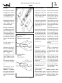
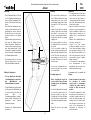
Baustufe 1, Vorbereiten der Tragfläche
Nr. Bezeichnung, Maße in mm Stück
1.1 Ruder, angeformt 2
1.2 Tragflächenhälfte, rechts 1
1.3 Tragflächenhälfte, links 1
1.4 Scharnierband oben, Tesafilm 2 n.e.
1.5 Scharnierband unten, Tesafilm 6 n.e.
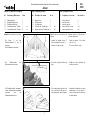
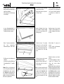
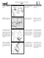
Hinweis: Es wird mit Speed 2 geklebt.
- Die Ruder 1.1 von den
Tragflächenhälften 1.2 und 1.3
abtrennen
- Die Schnittkanten verschleifen.
- Die Kühlluftschlitze der
Motorgondeln ausschneiden.
- Die Tragflächenhälften zusammen-
setzen, deckungsgleich zueinander
ausrichten und mit
Klebebandstreifen fixieren.
1
1.1
Note: use Speed 2 cyano adhesive for
all joints.
- Separate the integral elevons 1.1
from the wing panels 1.2 and 1.3.
- Sand the cut edges smooth.
- Cut out the cooling slots in the motor
pods.
- Fit the wing panels together at the
root, check that they line up accu-
rately, and tape the panels together.
Stade 1, préparatifs sur l'aile
N° désignation, cotes en mm nbre de pièces
1.1 aileron, façonné 2
1.2 demi-aile, droite 1
1.3 demi-aile, gauche 1
1.4 bande charnière en haut 2 n.c.
1.5 bande charnière en bas 6 n.c.
Stage 1, preparing the wings
No. Description, size in mm No. off
1.1 Integral elevon 2
1.2 R.H. wing panel 1
1.3 L.H. wing panel 1
1.4 Top hinge strip, Tesafilm tape 2 N.I.
1.5 Bottom hinge strip, Tesafilm tape 6 N.I.
À noter : coller avec de la colle cyano-
acrylate Speed type 2.
- Retirer les ailerons 1.1 des demi-
ailes 1.2 et 1.3
- Poncer les arêtes de coupe.
- Entailler les fentes d'aération des
nacelles de moteur.
- Assembler les demi-ailes, les ajuster
parfaitement l'une par rapport à
l'autre et les fixer avec des morceaux
de ruban adhésif.
No.
3129
1.2
2
3
1.3
1.1

Airbull
6
Bauanleitung, Assembly instructions, Notice de montage
No.
3129
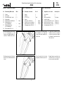
- Tragflächenhälften mit Sekunden-
kleber, der an den Stoßstellen einge-
träufelt wird, verkleben.
Klebevorgang mit Aktivatorspray
beschleunigen.
- Je einen Scharnierbandstreifen 1.4
(Tesafilm) mit halber Breite über die
Tragflächenhinterkante spannen.
- Ruder 1.1 ansetzen und andrücken.
Auf einen ausreichenden
Ruderausschlag von ca. 30° achten.
- Die Ruder nach oben klappen und
andrücken.
- Jeweils außen und in der Mitte kurze
Scharnierbandstücke 1.5 gegenkle-
ben.
Hinweis: Wenn eine Lackierung mit
rocolor Arcel gewünscht wird, ist diese
zweckmäßigerweise jetzt vorzuneh
-
men.
Beachten: Alle Klebestellen für
Servos, Motor
en, Seitenleitwerke etc.
abkleben, um später eine einwandfr
eie
Klebestelle zu gewährleisten.
- Glue the wings together by dribbling
cyano into the joint lines.
Apply activator spray to the joints to
accelerate curing.
- Apply a full-length strip of hinge
tape (Tesafilm) 1.4 along the trailing
edge of the wing, leaving half its
width projecting.
- Position the elevon 1.1 accurately
and press it onto the tape. Make
sure that the elevon is able to
deflect up and down through about
30°. Repeat with the other wing
panel.
- Fold the elevons up and over, and
hold them against the wing.
- Apply short strips of hinge tape 1.5
at both ends and in the centre to
secure the hinge.
Note: if you intend to paint the model
using rocolor Arcel, this is a good time
to apply the finish.
Important: mask
out all joint areas where servos,
motors, fins etc. ar
e to be glued, as
the glue must be applied to the bar
e
foam.
- Coller les demi-ailes en faisant coller
des gouttes de colle cyanoacrylate
sur les joints. Accélérer l'adhésivité
en pulvérisant un activateur en
bombe.
- Appliquer chaque fois une bande
charnière 1.4 (ruban adhésif) sur la
moitié de la largeur de l'arête arrière
de l'aile.
- Mettre l'aileron 1.1 en place et la
presser.
Veiller à obtenir un débattement
d'aileron d'approx. 30 °.
- Rabattre les ailerons vers le haut et
presser.
- À l'extérieur, appliquer à l'opposé
chaque fois, à l'extérieur et au
milieu, des courtes bandes
charnières 1.5.
À noter : lorsqu'une mise en peinture est
souhaitée avec une peinture rocolor Arcel,
il est rationnel d'appliquer la peinture main-
tenant.
Attention : appliquer un mor
ceau
de ruban adhésif sur tous les points de
collage ultérieurs des servos, des moteurs,
des gouver
nes de dir
ection, etc., afin d'as
-
sur
er une bonne adhér
ence ultérieur
e.
4
5
6
7
30°
1.5
1.4
1.1
1.4
1.1
1.5
1.4

Airbull
7
Bauanleitung, Assembly instructions, Notice de montage
Baustufe 2, Einbau der Servos
Nr. Bezeichnung, Maße in mm Stück
2.1 Servo 2 n.e.
2.2 Sternhebel 2 bei 2.1
2.3 Ruderhorn 2
2.4 Gestängekupplung 2
2.5 Schraube M 2 x 6 2
2.6 Rudergestänge, Ø 1,2 x 160 2
Hinweis: Die Servoschächte sind für
Standardservos vorgesehen. Je nach
Servo kann es erforderlich sein, die
Schächte nachzuarbeiten.
Bei Bedarf Servo-Verlängerungskabel
verwenden.
- Die Steuerscheiben von den Servos
2.1 entfernen. Die Servos in
Neutralstellung bringen.
- Sternhebel so aufsetzen daß ein
Anlenkarm rechtwinklig zur Servo-
Längsachse steht. Diesen Arm nicht
abschneiden.
- Beschnittene Hebel spiegelbildlich
aufstecken und mit den
Servohebelschrauben sichern.
- Die Servos können wahlweise mit
Sekundenkleber oder mit
Doppelklebeband in den Schächten
fixiert werden.
- Servos einsetzen, fixieren.
S
tage 2, installing the servos
No. Description, size in mm No. off
2.1 Servo 2 N.I.
2.2 “Star” output lever 2 With 2.1
2.3 Elevon horn 2
2.4 Pushrod connector 2
2.5 Screw, M2 x 6 2
2.6 Elevon pushrod, 1.2 Ø x 160 2
Note: the servo wells are designed to
accept standard servos. You may need
to adjust the wells slightly to suit your
servos.
You are likely to need servo extension
leads.
- Remove the output discs from the
servos 2.1. Set the servos to neutral
(centre).
- Place the “star” output lever on the
servo output shaft with one arm at
right-angles to the long side of the
servo. Mark this arm, remove the
output device and cut off all the
other arms as shown.
- Fit the trimmed output arms on the
servos to make a mirror-image pair.
Fit the output screws to secure the
output arms.
- The servos can be glued in the wells
using cyano; alternatively you may
prefer to use double-sided foam
tape.
- Fit the servos and secure them.
Stade 2, mise en place des servos
N° désignation, cotes en mm nbre de pièces
2.1 servo 2 n.c.
2.2 palonnier en étoile 2 avec 2.1
2.3 guignol 2
2.4 accouplement de tringle 2
2.5 vis, M 2 x 6 2
2.6 tringle d'aileron, Ø 1,2 x 160 2
À noter : les logements des servos
sont conçus pour des servos standard.
En fonction du servo utilisé, il peut
s'avérer nécessaire de retravailler le
logement. Si nécessaire, utiliser un
cordon-rallonge de servo.
- Retirer les palonniers circulaires des
servos 2.1. Amener les servos au
neutre à l'aide de l'ensemble de
radiocommande
- Mettre le palonnier en étoile en place
de manière que le bras d'asservisse-
ment se trouve perpendiculaire à
l'axe longitudinal du servo. Ne pas
couper ce bras.
- Mettre les palonniers coupés en
place de manière symétrique et les
fixer avec les vis des servos.
- Les servos peuvent être fixés dans
les logements avec de la colle
cyanoacrylate ou avec des
morceaux de ruban adhésif double
face.
-
Installer les servos et les fixer.
No.
3129
2.2
2.1
8
9
10
2.2
2.1

Airbull
8
Bauanleitung, Assembly instructions, Notice de montage
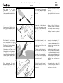
- Die Öffnungen der Kabelkanäle zum
Empfängerschacht so mit einer Feile
erweitern, dass die Servostecker
durchgeschoben werden können.
- Die Servokabel verlegen, die Stecker
durchschieben.
- Die Kabel mit Klebebandstreifen
sichern.
- Die äußeren Löcher der Ruderhörner
2.3 auf 1,8 – 2 mm aufbohren.
- Die Gestängekupplungen 2.4 mit
den Schrauben 2.5 an den
Ruderhör
nern lose verschrauben.
- Continue the cable ducts into the
receiver well using a file, so that the
servo plugs can be pushed through.
- Deploy the servo leads in the slots
and push the plugs through into the
fuselage.
- Apply tape over the cable slots as
shown.
- Open up the outermost holes in the
elevon horns 2.3 to a diameter of 1.8
- 2 mm.
-
Attach the pushr
od connectors 2.4
to the hor
ns loosely using the scr
ews
2.5.
- Agrandir les ouvertures des conduits
des cordons vers le logement du
récepteur à l'aide d'une lime de telle
sorte qu'il soit possible d'y faire
passer les connecteurs des servos.
- Agencer les cordons des servos,
enfiler les connecteurs.
- Fixer les cordons à l'aide de
morceaux de ruban adhésif.
- Porter les trous extérieurs des guig-
nols 2.3 à 1,8 – 2 mm en perçant.
- Visser lâchement les accouplements
de tringle 2.4 avec les vis 2.5 aux
guignols.
No.
3129
12
13
11
2.4
2.5
2.3
2.4
Ø 1,8 - 2 mm
2.5

Airbull
9
Bauanleitung, Assembly instructions, Notice de montage
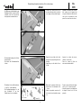
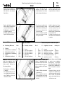
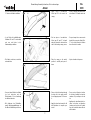
- Die Bohrungen für die Ruderhörner
in den Rudern 1.1 durchstechen.
- Die Rudergestänge 2.6 in den
Servohebeln 2.2 einhängen.
- Die Gestängekupplungen 2.4 auf die
Gestänge 2.6 fädeln.
- Die Ruderhörner 2.3 in die
Bohrungen der Ruder stecken, aus-
richten und mit Sekundenkleber ver-
kleben.
- Die Ruder in Neutralstellung bringen.
Dazu ein Lineal an der Unterseite
anlegen.
- Die Schrauben der Gestängekupp-
lungen 2.5 anziehen.
- Pierce the holes in the elevons 1.1 to
accept the horns 2.3.
- Connect the pushrods 2.6 to the
servo output arms 2.2.
- Slip the pushrods 2.6 through the
pushrod connectors 2.4.
- Push the horns 2.3 into the holes in
the elevons. Position them accurate-
ly and fix each in place with a drop of
cyano.
- Set the elevons to neutral by laying a
ruler on the underside of the wing as
shown.
- Tighten the screws in the pushrod
connectors 2.5.
- Percer les alésages pour les guig-
nols dans les ailerons 1.1.
- Accrocher la tringle d'aileron 2.6
dans chacun des palonniers de
servo.
- Enfiler l'accouplement de tringle 2.4
sur la tringle 2.6.
- Planter les guignols 2.3 dans les
alésages des ailerons, les aligner et
les coller avec de la colle cyanoacry-
late..
- Amener les ailerons en position neu-
tre.
Pour ce faire, installer une règle sur
l'intrados.
-
Serr
er les vis des accouplements de
tringle 2.5.
No.
3129
2.6
16
17
15
18
2.2
2.6
2.4
14
1.1
Ø 3 mm
Ø 3 mm
2.5
2.5
2.3
5 mm

Airbull
10
Bauanleitung, Assembly instructions, Notice de montage
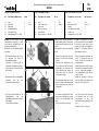
- Die Motoren 3.1 entstören. Dazu die
Kondensatoren 3.2 mit jeweils einem
Beinchen an das Gehäuse löten,
welches dazu blankzufeilen ist.
Zweites Beinchen mit
Isolierschlauch 3.3 versehen und an
die Motorpole stecken.
- Die Beinchen der Kondensatoren 3.4
mit Isolierschlauch versehen und
ebenfalls an die Motorpole stecken.
- Das Motoranschlußkabel 3.5 und 3.6
ablängen und an die Motorpole
löten; die Kondensatoren werden
dabei mitverlötet.
Beim Anlöten
beachten
: Das schwarze Kabel
jeweils an den Motorpol löten, der
mit einem roten Punkt gekennzeich-
net ist.
- Die E-Motoren 3.1 so in die einge-
formten Halbschalen mit Speed 2
einkleben, daß das Gehäuse bündig
mit der Triebwerksgondel-
Hinterkante abschließt. Beachten,
daß sich die Kühlluftschlitze von
Motor und Motor
gondel decken.
- The motors 3.1 must be suppressed
before they are installed: file two
areas of the motor can perfectly
clean. Solder one pin of one capaci-
tor 3.2 to the can. Slip an insulating
sleeve 3.3 on the other pin and push
the end through one motor terminal.
Repeat with the second capacitor
3.2 and the other motor terminal.
- Slip insulating sleeves on both pins
of the capacitor 3.4 and thread the
pin ends through both motor termi-
nals.
- Cut the power leads 3.5 and 3.6 to
length and solder the ends to the
motor terminals, soldering the
capacitor pins at the same time.
As
the motors are used in pusher
mode, be sure to solder the black
wire to the motor terminal marked
with a red dot. Suppress the second
motor using the same procedure.
- Position the electric motors 3.1 in
the moulded-in pods with the can
flush with the rear edge of the pod.
Check that the motor cooling slots
line up with the pod slots, then glue
the motors in place using Speed 2
cyano.
- Antiparasiter les moteurs 3.1. Pour
ce faire, souder chaque fois une
broche des condensateurs 3.2 au
carter du moteur, à un emplacement
limé au préalable.
Munir la seconde broche d'une gaine
isolante 3.3 et la planter sur le pôle
indiqué du moteur.
- Munir les broches des condensa-
teurs 3.4 de gaine isolante et les
planter également sur le pôle indiqué
du moteur.
- Raccourcir le cordon de connexion
des moteurs 3.5 et 3.6 et souder aux
pôles des moteurs en soudant simul-
tanément les broches des conden-
sateurs.
En soudant observer ce
qui suit : souder systématiquement
le brin noir au pôle du moteur muni
d'un point rouge.
- Coller les moteurs électriques 3.1
dans les demi-coquilles moulées, à
l'aide de colle cyanoacrylate de type
2, de telle sorte que le carter se trou-
ve à fleur de l'arête arrière de la
nacelle du moteur. Veiller à ce que
les fentes de refroidissement du
moteur coïncident avec celles de la
nacelle du moteur.
No.
3129
Baustufe 3, der Antrieb
Nr. Bezeichnung, Maße in mm Stück
3.1 E - Motor 2
3.2 Entstörkondensator, 100 nF 4
3.3 Isolierschlauch 8
3.4 Entstörkondensator, 47 nF 2
3.5 Motoranschlußkabel, rot,
200 lang, 2
3.6 Motoranschlußkabel, schwarz,
200 lang 2
3.7 Regler 1, n.e.
Stage 3, the power system
No. Description, size in mm No. off
3.1 Electric motor 2
3.2 Suppressor capacitor, 100 nF 4
3.3 Insulating sleeve 4
3.4 Suppressor capacitor, 47 nF 2
3.5 Motor power lead, red, 200 long 2
3.6 Motor power lead, black, 200 long 2
3.7 Speed controller 1 N.I.
Stade 3, l'entraînement
N° désignation, cotes en mm nbre de pièces
3.1 moteur électrique 2
3.2 condensateur d'antiparasitage,100 nF 4
3.3 gaine isolante 4
3.4 condensateur d'antiparasitage,47 nF 2
3.5 brin de connexion du moteur
rouge, 200 de long 2
3.6 brin de connexion du moteur
noir, 200 de long 2
3.7 variateur 1, n.c.
20
3.2
3.1
3.3
3.4
3.5
3.3
3.3
3.3
3.6
19
3.1
3.1
3.5
3.5
3.6
3.6

Airbull
11
Bauanleitung, Assembly instructions, Notice de montage
No.
3129
Die Kabel zur Tragflächenmitte
führen und in den Kabelschächten
verlegen.
- Hinweis: Die Motoren werden paral-
lel geschaltet - Schaltbild beachten.
- Kabel so ablängen, daß jeweils die
roten Kabel in der linken, die
schwarzen Kabel in der rechten
Vertiefung zusammengeführt werden
können. Isolation an den
Kabelenden entfernen, Kabel jeweils
miteinander verdrillen und miteinan-
der verlöten.
- Den Regler 3.7 in den Reglerschacht
einsetzen. Motoranschlußkabel des
Reglers so kürzen, dass sie direkt zu
den Lötstellen geführt werden kön-
nen.
- Run the motor cables through to the
wing centre section and push them
into the cable slots.
- Note: the motors must be wired in
parallel - see wiring diagram.
- Cut the cables to correct length: the
two red wires should lie in the left-
hand recess, the black wires in the
right-hand recess. Strip the insula-
tion from the wire ends, twist them
together and solder the joints.
- Place the speed controller 3.7 in the
controller well. Shorten the motor
leads attached to the controller to
the point where they coincide accu-
rately with the solder joint positions.
- Disposer les cordons vers le milieu
de l'aile et les agencer dans les loge-
ments de cordon.
- À noter : les moteurs sont montés
électriquement en parallèle – tenir
compte des indications du schéma
électrique.
- Raccourcir les cordons de telle sorte
qu'il soit possible systématiquement
de réunir les brins rouges dans la
concavité gauche et les brins noirs
dans la concavité droite. Retirer la
gaine isolante à l'extrémité des
brins, entortiller les extrémités des
brins ensemble et les souder.
- Mettre le variateur 3.7 en place dans
le logement du variateur, raccourcir
le brin de connexion du moteur du
variateur de telle sorte qu'il puisse
être directement acheminé à l'em-
placement du soudage.
21
22
23
24
3.1-3.4
3.5
3.6
(4.5)
3.7
3.6
3.5
3.7

Airbull
12
Bauanleitung, Assembly instructions, Notice de montage
- Das weiße Motoranschlußkabel des
Reglers mit dem roten Kabel, das
blaue Kabel mit dem schwarzen
Kabel verlöten.
- Regler in das Reglerfach einsetzen,
dabei die Akku-Anschlußkabel nach
vorn in den Akkuschacht führen.
- Die Motorkabel in die Vertiefungen
der Tragfläche eindrücken.
- Bei Einsatz stärkerer Motoren den
Regler im Kühlluftstrom platzieren.
- Locate the blue and white wires
attached to the speed controller.
Solder the white wire to the red wire,
and the blue wire to the black wire.
- Place the speed controller in the
controller well, running the battery
cables forward into the battery well.
- Push the motor leads into the
recesses in the wing.
- If you are using more powerful
motors take care for a good cooling
of the speed controller.
- Souder le brin de connexion du
moteur du variateur blanc au brin
rouge, le brin bleu avec le brin noir.
- Installer le variateur dans le loge-
ment du variateur en acheminant le
cordon de connexion de l'accu vers
l'avant dans le logement de l'accu.
- Enfoncer les brins du moteur dans
les concavités de l'aile.
- En utilisant des moteurs plus puis-
sant, veiller à un bon refroidissement
du variateur.
No.
3129
25
26
Baustufe 4, RC-Einbau
Nr. Bezeichnung, Maße in mm Stück
4.1 Empfänger 1 n.e.
4.2 Klettbandstück, nicht selbstklebend 1 40 lg
4.3 Klettbandstück, selbstklebend 1 40 lg
4.4 Klettbandstück, nicht selbstklebend 2 40 lg
4.5 Flugakku 1 n.e.
4.6 Klettbandstück, selbstklebend 2 40 lg
Hinweis: Die Steuerung des Airbull
erfolgt über kombinierte Quer-/
Höhenruder. Den Deltamischer des
Senders gemäß Anleitung der
Fernsteuerung aktivieren.
- Die Litzenantenne des Empfängers
4.1 abwickeln.
- Vom Empfängerschacht aus ein
Loch schräg durch die linke oder
rechte Tragfläche stechen und
Litzenantenne einfädeln.
27
Note: the Airbull is controlled using
elevons, i.e. superimposed ailerons
and elevators. At this point you should
activate the delta mixer in your trans-
mitter, as described in your RC system
instructions.
-
Unwind the flexible aerial attached
to the receiver 4.1.
-
Pierce an angled hole from the
receiver well through the left or right
wing and thread the receiver aerial
thr
ough it.
Stage 4, RC installation
No. Description, size in mm No. off
4.1 Receiver 1 N.I.
4.2 Velcro tape, non-adhesive 1 40 long
4.3 Velcro tape, self-adhesive 1 40 long
4.4 Velcro tape, non-adhesive 2 40 long
4.5 Flight battery 1 N.I.
4.6 Velcro tape, self-adhesive 2 40 long
Stade 4, mise en place de l'ensemble de réception
N° désignation, cotes en mm nbre de pièces
4.1 récepteur 1 n.c.
4.2 bande Velcro, non autocollant 1 40 de long
4.3 bande Velcro, autocollant 1 40 de long
4.4 bande Velcro, non autocollant 2 40 de long
4.5 accu d'alimentation des moteurs 1 n.c.
4.6 bande Velcro, autocollant 2 40 de long
À noter : le pilotage du modèle Airbull
est assuré par une combinaison
ailerons/gouverne de profondeur.
Activer le dispositif de mixage delta de
l'émetteur selon les indications de la
notice de l'ensemble de radiocom-
mande.
-
Développer l'antenne souple du
récepteur 4.1. En partant du loge-
ment du récepteur percer un trou de
biais en travers de la demi-aile
gauche ou de la demi-aile dr
oite et y
enfiler l'antenne souple.
4.1

Airbull
13
Bauanleitung, Assembly instructions, Notice de montage
- Ein Klettbandstück 4.2 zuschneiden
und in den Empfängerschacht kle-
ben.
- Den Empfänger 4.1 mit einem
selbstklebenden Klettbandstück 4.3
versehen.
- Servos und Regler gemäß der
Anleitung der Fernsteuerung am
Empfänger anschließen, Empfänger
einsetzen.
- Die Kabel mit einem
Klebebandstreifen fixieren.
- Im Akkuschacht zwei
Klettbandstücke 4.4 verkleben. Den
Akku 4.5 mit Klettbandstücken 4.6
versehen und in den Akkuschacht
einlegen.
- Cut a piece of Velcro tape 4.2 to
length and glue it in the receiver well.
- Apply a piece of self-adhesive Velcro
tape 4.3 to the receiver 4.1.
- Connect the servos and speed con-
troller to the receiver as described in
your RC system instructions, and fit
the receiver in the model.
- Secure the cables with a strip of
adhesive tape.
- Glue two pieces of Velcro tape 4.4 in
the battery well. Apply the pieces of
Velcro tape 4.6 to the flight battery
4.5 and place the pack in the battery
well.
- Couper un morceau de bande Velcro
4.2 et le coller dans le logement du
récepteur.
- Munir le récepteur 4.1 d'un morceau
de bande Velcro autocollante 4.3.
- Raccorder les servos et le variateur
au récepteur selon les indications de
la notice de l'ensemble de radio-
commande et mettre le récepteur en
place.
- Fixer les cordons avec un morceau
de ruban adhésif.
- Dans le logement de l'accu, coller
deus morceaux de bande Velcro 4.4.
Munir l'accu 4.5 de morceaux de
bande Velcro 4.6 et l'installer dans le
logement de l'accu.
No.
3129
30
28
29
4.1
4.2
4.3
4.5
4.4
4.6
(3.7)

Checking the working systems
- Connect the radio control system
completely, ready to work. Set the
throttle stick to the “motors off”
position, then switch the transmitter
on. Connect the flight battery.
- Set up the speed controller following
the instructions supplied with the
unit. Once adjusted correctly the
motors should not run so long as the
throttle stick is at “off”.
- Open the throttle slowly, and check
the direction of motor rotation. Both
motor shafts should rotate clockwise
when viewed from behind the model.
If this is not the case (e.g. if you are
using components other than the
recommended ones), unsolder the
power leads at the motor terminals
and swap them over.
- Both elevons should now be in the
neutral position.
- Check the direction of travel of the
elevons: when you pull the elevator
stick back towards you, the trailing
edge of both elevons should rise.
- Move the aileron stick to the right,
and the trailing edge of the right-
hand elevon should rise, the left-
hand elevon fall.
- If either function works the wrong
way round, reverse that channel at
the transmitter (servo reverse).
- Set the elevon travels to the values
stated in the drawing.
Note: the travels must be set sepa
-
rately for each function. When the
control functions are superimposed
the travels will be dif
fer
ent.
Airbull
14
Bauanleitung, Assembly instructions, Notice de montage
Funktionsprobe
- Die Fernsteuerung betriebsbereit
anschließen. Erst den Sender ein-
schalten. Der Gasknüppel muß sich
in der Stellung „Motoren Aus“ befin-
den. Den Flugakku anschließen.
- Den Regler gemäß der Anleitung, die
dem Gerät beiliegt, einstellen. Nach
erfolgter Einstellung dürfen die
Motoren jetzt nicht anlaufen.
- Gas geben, Motorlaufrichtung prü-
fen. Die Motoren müssen von hinten
gesehen im Uhrzeigersinn drehen.
Sollte dies nicht der Fall sein, (z. B.
bei Verwendung anderer, als der von
uns empfohlenen Komponenten),
die Motorkabel an den Lötstellen der
Motorpole durch Umlöten vertau-
schen.
- Die Ruder müssen sich in
Neutralstellung befinden.
- Laufrichtung der Ruder prüfen. Bei
Ziehen des Höhenruderknüppels
zum Körper hin müssen sich die
Hinterkanten der Ruder heben.
- Bei Bewegen des
Querruderknüppels nach rechts muß
sich die Hinterkante des rechten
Ruders heben, die des linken sen-
ken.
- Bei vertauschten Ruderfunktionen
Servo - Reverse des Senders betäti-
gen.
- Die Ruderausschläge nach den
angegebenen Werten einstellen.
Beachten: Die Ausschlaggrößen
müssen separat eingestellt wer
den.
Bei überlagerten Steuerfunktionen
ergeben sich entsprechend andere
Werte.
Essai des fonctions
- Raccorder l'ensemble de radiocom-
mande en ordre de marche. Mettre
d'abord l'émetteur en marche. Le
manche des gaz doit se trouver en
position „Moteur arrêté“. Raccorder
l'accu d'alimentation des moteurs.
- Régler le variateur en fonction des
indications de la notice qui l'accom-
pagne. Une fois le réglage réalisé, il
ne faut pas que les moteurs démar-
rent pour l'instant.
- Donner des gaz et observer le sens
de rotation des moteurs. Vu de l'ar-
rière, les moteurs doivent tourner
dans le sens des aiguilles d'une mon-
tre. Si ce n'est pas le cas (par exem-
ple lorsqu'on a mis en œuvre des
composants autres que ceux que
nous recommandons), intervertir les
brins du moteur au niveau des
emplacements soudés sur les pôles
des moteurs.
- Les ailerons doivent se trouver au
neutre.
- Contrôler le sens de déplacement
des ailerons. Lorsqu'on tire le
manche de profondeur vers soi, il faut
que l'arête arrière des ailerons
s'élève.
- Lorsqu'on déplace le manche des
ailerons vers la droite, il faut que
l'arête arrière de l'aileron droit s'élève
et celle de l'aileron gauche descende.
- Si les fonctions sont inversées,
actionner le dispositif d'inversion de
la course des servos sur l'émetteur.
- Régler le débattement des ailerons
sur les valeurs indiquées.
Attention : les grandeurs de débatte
-
ment doivent êtr
e mises au point
séparément. Lorsque les fonctions de
commande sont solidaires, d'autres
valeurs appr
opriées apparaissent.
No.
3129
32
31
8 mm
8 mm
8 mm
8 mm
Ausschläge für Höhenruder
Elevator travels
Débattement de la gouverne de profondeur
Ausschläge für Querruder
Aileron travels
Débattement de l'aileron

Airbull
15
Bauanleitung, Assembly instructions, Notice de montage
- Mit einem Balsamesser einen Schlitz
für die Litzenantenne in die
Unterseite der Tragflächenhälfte ein-
schneiden - Schlitztiefe max. 2 mm.
- Die Litzenantenne in den Schlitz ein-
drücken und mit Klebebandstreifen
sichern.
No.
3129
- Cut a slot for the receiver aerial in
the underside of one wing panel
using a balsa knife; maximum slot
depth 2 mm.
- Press the aerial into the slot and
apply strips of adhesive tape over it.
- À l'aide d'un couteau à balsa
entailler une fente pour l'antenne
souple du récepteur dans l'intrados
de la demi-aile – profondeur de l'en-
taille max.2 mm.
- Engager l'antenne souple du récep-
teur dans la fente et l'y fixer avec
des morceaux de ruban adhésif.
34
Baustufe 5, Fertigstellen des Modells
Nr. Bezeichnung, Maße in mm Stück
5.1 Spinner 2
5.2 Luftschraube 2
5.3 Seitenleitwerk, links / rechts je 1
5.4 Kabinenhaube 1
5.5 Klettbandstück, selbstklebend 1 20 lg
5.6 Klettbandstück vorn,
nicht selbstklebend 1 20 lg
5.7 Klettbandstück hinten,
nicht selbstklebend 1 25 lg
5.8 Blechschraube Ø 2,9 x 22 1
Stage 5, completing the model
No. Description, size in mm No. off
5.1 Spinner 2
5.2 Propeller 2
5.3 Fin, L.H. / R.H. 1 each
5.4 Canopy 1
5.5 Velcro tape, self-adhesive 1 20 long
5.6 Front Velcro tape, non-adhesive 1 20 long
5.7 Rear Velcro tape, non-adhesive 1 25 long
5.8 Self-tapping screw, 2.9 Ø x 22 1
Stade 5, finition du modèle
N° désignation, cotes en mm nbre de pièces
5.1 cône d'hélice 2
5.2 hélice 2
5.3 dérive, gauche/droite 1 de chaque
5.4 verrière de cabine 1
5.5 morceau de bande Velcro, autoc. 1 20 de long
5.6 bande Velcro avant non autoc. 1 20 de long
5.7 bande Velcro arrière, non autoc 1 25 de long
5.8 vis autotaraudeuse Ø 2,9 x 22 1
33

Airbull
16
Bauanleitung, Assembly instructions, Notice de montage
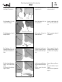
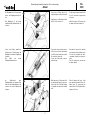
- Fit the spinners 5.1 on the propellers
5.2 as shown.
Note: the engraving
on the propeller blades must face
the rear.
- Apply a drop of liquid detergent to
the bore of the propellers and push
them onto the motor shafts as far as
they will go, holding the motors firm-
ly.
- You will find the template “S” on the
accessory sheet; copy the shape
onto a piece of stiff card. The tem-
plate is used to set the fins 5.3 at the
correct angle.
- The fins should be glued in the
recesses in the wing using cyano;
note that the moulded-in bulge
should be on the outboard side. Set
the fins at the correct angle using the
template, than apply activator to
accelerate the cure.
- Cut out the moulded canopy 5.4
along the marked lines. File a slot of
the stated size in the centre of the
front end.
- Planter les cônes d'hélice 5.1 sur les
hélices 5.2.
Attention : les inscriptions sur les
pales des hélices doivent se trouver
à l'arrière.
- Glisser les hélices 5.2 le plus pro-
fondément possible sur les arbres
des moteurs en utilisant une goutte
de produit pour la vaisselle.
Maintenir les moteurs pendant
l'opération.
- Reporter le schéma du gabarit „S “
pour l'alignement des dérives 5.3 sur
un morceau de carton approprié. Le
schéma se trouve sur le feuillet des
accessoires joint.
- Installer les dérives dans les concav-
ités de l'aile après les avoir enduites
de colle cyanoacrylate. Le bourrelet
moulé se trouve systématiquement à
l'extérieur. Aligner les dérives à l'aide
du gabarit, les coller et accélérer
l'adhésivité avec un activateur en
bombe.
- Découper la verrière de cabine 5.4
en fonction des repères. Entailler la
fente indiquée à l'aide d'une lime en
fonction des cotes fournies.
No.
3129
- Die Spinner 5.1 auf die
Luftschrauben 5.2 stecken.
Beachten: Die Schrift auf den
Luftschraubenblättern muß sich hin-
ten befinden.
- Luftschrauben 5.2 unter
Verwendung von Spülmittel mög-
lichst tief auf die Motorwellen schie-
ben. Die Motoren dabei festhalten.
- Die Schablone „S“ zum Ausrichten
der Seitenleitwerke 5.3 auf einen
geeigneten Karton übertragen. Die
Zeichnung der Schablone befindet
sich auf dem Zubehörblatt.
- Seitenleitwerke unter Zugabe von
Sekundenkleber in die Vertiefungen
der Tragfläche einsetzen. Der ange-
formte Wulst liegt jeweils außen.
Leitwerke mit der Schablone aus-
richten. Klebung mit Aktivator
beschleunigen.
- Die Kabinenhaube 5.4 nach
Markierungen ausschneiden. Den
Schlitz nach Maßangaben mittig
einfeilen.
38
5.1
5.2
“S”
5.1, 5.2
5.3
36
37
35
5.4
3 mm
5 mm

Airbull
17
Bauanleitung, Assembly instructions, Notice de montage
Ein Stück selbstklebendes Klettband
5.5 hinten in die Kabine einkleben.
- Je ein Stück nicht selbstklebendes
Klettband 5.6 und 5.7 zuschneiden
und vorn und hinten in der
Kabinenauflage verkleben.
- Die Kabine aufsetzen, ausrichten
und andrücken.
- Vorn nach dem Schlitz in der Kabine
ein Loch einstechen und die
Blechschraube 5.8 zur Arretierung
der Kabine eindrehen.
-
Mit Anbringen der Dekorbilder
gemäß Kartonagenabbildungen ist
der Bau des Modells abgeschlossen.
No.
3129
- Apply a piece of self-adhesive
Velcro tape 5.5 to the rear of the
canopy.
- Cut two pieces of non-adhesive
Velcro tape 5.6 and 5.7 to length
and glue them at the front and rear
ends of the fuselage canopy recess.
- Place the canopy on the model,
position it carefully and press it
down.
- Pierce a hole in the fuselage through
the front slot in the canopy, and fit
the self-tapping screw 5.8 to secure
it.
- Apply the decals as shown in the kit
box illustrations to complete your
model.
- Coller un morceau de bande Velcro
autocollante 5.5 à l'arrière de la cab-
ine.
- Couper chaque fois un morceau de
bande Velcro non autocollante 5.6 et
5.7 et les coller à l'avant et à l'arrière
dans l'assise de la cabine.
- Ajuster la cabine et la presser.
- Percer un trou à l'avant en fonction
de la fente et installer la vis autota-
raudeuse 5.8 pour bloquer la cab-
ine.
-
Appliquer les autocollants de déco
-
ration en fonctions es indications
four
nies par les photos de l'embal
-
lage. La construction du modèle est
ainsi terminée.
5.5
40
42
41
39
5.4
5.6
5.7
5.8

Airbull
18
Bauanleitung, Assembly instructions, Notice de montage
Auswiegen
- Der Schwerpunkt liegt bei 150 mm
von der Tragflächenhinterkante aus
gemessen. Den Schwerpunkt „C.G.“
mit den „CG“-Zeichen (Dekor) mar-
kieren.
- Das Modell im Schwerpunkt unter-
stützen und auspendeln lassen. Die
Idealstellung ist erreicht, wenn das
Modell mit leicht nach unten hän-
gendem Vorderteil in der Waage
bleibt.
- Flugakku entsprechend verschieben.
- Erst, wenn das Trimmen mit dem
Akku nicht ausreicht, Trimmblei ver-
wenden, welches entsprechend vorn
bzw. hinten platziert wird. Schlitz
einschneiden, Trimmblei eindrücken
und bei korrekter Schwerpunktlage
mit Sekundenkleber fixieren.
- Bei Verwendung der von uns emp-
fohlenen Komponenten ist in der
Regel kein Trimmblei erforderlich.
Einfliegen, Flughinweise
- Vor dem Erstflug die Abschnitte
„Routineprüfungen vor dem Start“
und „Modellbetrieb“ der
Sicherheitshinweise beachten.
- Für den Erstflug einen nicht zu windi-
gen Tag aussuchen. Als Gelände eig-
net sich eine flache, freie Wiese am
besten. Nähe von
Hochspannungsleitungen, verkehrs-
r
eichen Straßen, Ansiedlungen und
Flugplätzen sowie ander
en
Hindernissen meiden.
- Nochmals eine Funktionskontrolle
dur
chführ
en.
Balancing
- The correct Centre of Gravity posi-
tion is 150 mm forward of the wing
trailing edge at the centre section
(see drawing). Measure this location
and apply the “CG” decal at that
point.
- Support the model at the marked
points on either side of the fuselage
and allow it to hang freely. The
model is correctly balanced when it
remains level, with the nose angled
slightly down.
- If necessary, adjust the position of
the flight pack to set the correct bal-
ance point.
- If it is not possible to balance the
model correctly by re-positioning the
flight pack, add lead ballast at nose
or tail. This is done by cutting a slot
and pushing the lead into it. Re-
check the CG, then secure the bal-
last with cyano.
- If you use the recommended com-
ponents it should not be necessary
to use lead ballast.
Test-flying, flying notes
- Before test-flying the model be
sure to read the sections “Routine
pre-flight checks” and “Operating
the model”.
- For the first flight wait for a day with
no more than a gentle breeze. The
flying site should be a large, flat,
unobstructed field. Keep well away
from high-tension overhead cables,
busy r
oads, r
esidential ar
eas and air-
fields.
- Repeat the check of the working
systems.
Équilibrage
- Le centre de gravité se trouve à peu
près à 150 mm, mesurés à partir de
l'arête arrière de l'aile. Repérer le
centre de gravité à l'aide de l'abrévi-
ation „CG “ faisant partie des auto-
collants de décoration.
- Disposer le modèle sur une cale au
niveau de son centre de gravité et le
laisser en équilibre. Sa position est
idéale lorsque le modèle reste en
équilibre avec le nez légèrement
piqueur.
- Déplacer l'accu d'alimentation des
moteurs en conséquence.
- Lorsqu'il n'est pas possible
d'obtenir un équilibre correct avec
l'accu, utiliser du plomb de lestage
qui sera disposé à l'avant ou à l'ar-
rière dans des fentes entaillées à cet
effet et collé ensuite avec de la colle
cyanoacrylate lorsque l'équilibre
indiqué est atteint.
- Si vous utilisez les composants que
nous recommandons, il n'est
généralement pas nécessaire d'in-
staller du plomb de lestage.
Le premier vol et conseils de
pilotage
- Avant le premier vol, tenir compte
des consignes de sécurité
fournies par les paragraphes
„Contrôles de routines avant de
décoller“ et „Mise en œuvre du
modèle“.
- Pour effectuer le premier vol, choisir
de préférence un jour sans vent ou à
vent faible. Comme terrain de vol,
choisir une prairie dégagée, suff-
isamment vaste, en évitant la pr
ox
-
imité de lignes à haute tension, de
routes à fort encombrement, de
lotissements ou d'aéroports ou
d'autr
es obstacles.
No.
3129
150 mm

Airbull
19
Bauanleitung, Assembly instructions, Notice de montage
No.
3129
- Für den Handstart sollte ein Helfer anwesend sein, der
das Modell in die Luft befördern kann.
- Achtung: Beim Start nicht in die Druckluftschrauben
geraten - Verletzungsgefahr.
- Das Modell mit laufenden Motoren mit nicht zu geringem
Schub gerade und horizontal aus der Hand starten. Sofort
die Steuerung übernehmen.
- Nach dem Start den Steigflug nicht zu früh einleiten, son-
dern das Modell in flachem Horizontalflug Fahrt aufneh-
men lassen. Den Airbull dynamisch und weiträumig unter
Beibehaltung der Fahrt fliegen.
- Das Modell verhält sich gutmütig; d .h. Überziehen wird
durch deutliche Verminderung der Fluggeschwindigkeit
angezeigt. In diesem Fall nachdrücken und in den
Horizontalflug übergehen.
- Falls erforderlich, die entsprechenden Ruder nachtrim-
men.
- Das Flugverhalten genau beobachten. Sind Korrekturen
erforderlich, so sind diese nach der ersten Landung vor-
zunehmen.
Reparaturen
- Bei einer eventeuell erforderlichen Reparatur an den
Teilen wie folgt vorgehen:
- Bruchstelle freilegen, d. h. Dekor, Verschmutzung etc.
entfernen. Die Bruchstelle ansonsten so wenig wie mög-
lich verändern.
- Die Teile unter Zugabe von Sekundenkleber wieder paß-
genau zusammenfügen und ausrichten.
- Die Klebestelle gut aushärten lassen. Durch Klebstoff ent-
standene Unregelmäßigkeiten beschleifen.
robbe Modellsport GmbH & Co. KG
T
echnische Änderungen vorbehalten
- We strongly recommend that you ask a friend to launch
the model for you initially, so that you can concentrate
fully on flying.
- Caution: keep your hands well clear of the pusher pro-
pellers at launch time - injury hazard.
- Run up the motors to full speed and give the model a fair-
ly powerful launch, keeping the wings and fuselage hori-
zontal. Take control of the model the moment it leaves the
launcher’s hands.
- Keep the model flying straight and level at first so that it
has a chance to pick up plenty of speed before climbing.
A dynamic style of flying suits the Airbull best: keep the
airspeed up, and fly broad, sweeping turns wherever pos-
sible.
- The model is docile in the air, i.e. the stall is gentle and
simply causes a marked drop in airspeed. If you notice
this, apply down-elevator to return to level flight and build
up speed again.
- Adjust the trims if necessary.
- Observe the model’s behaviour in the air carefully. If cor-
rections to the trims are required, it is best to adjust the
mechanical linkages once the model is back on the
ground.
Repairs
- If any part should require repair, this is the procedure:
- Expose the break completely, i.e. remove decals, soiling
etc. Otherwise disturb the broken area as little as possi-
ble.
- Apply cyano glue to the surfaces of the break and push
the parts back together. Align them carefully and wait for
the glue to harden.
- Allow the joint to cure fully before flying again. Sand off
irregularities caused by the adhesive.
robbe Modellsport GmbH & Co. KG
We reserve the right to alter technical specifications.
Effectuer un nouveau contrôle des fonctions.
- Pour le lancement à la main, nous recommandons l'as-
sistance d'une tierce personne qui lancera le modèle.
- Attention : pour le lancement, ne pas approcher du plan
de rotation des hélices – risque de blessure.
- Les moteurs étant en marche, lancer le modèle avec un
bon élan et prendre immédiatement les commandes une
fois que le modèle a été lâché.
- Après le lancement, ne pas entamer de vol ascensionnel
trop tôt, mais laisser d'abord le modèle accélérer en vol
horizontal. Piloter le modèle Airbull dynamiquement et sur
de vastes espaces en conservant toujours une certaine
vitesse.
- Le modèle a un comportement relativement sain, c'est-à-
dire qu'un cabrage se manifeste immédiatement par une
réduction sensible de la vitesse. Dans ce cas, pousser sur
le manche de profondeur et rétablir un vol horizontal.
- Si nécessaire, corriger les gouvernes concernées à l'aide
des trims de réglage de précision.
- Observer avec précision le comportement en vol du mod-
èle. Si des corrections s'imposent, les réaliser après le
premier atterrissage.
Réparations
- Pour effectuer d'éventuelles réparations sur les éléments,
procéder comme suit :
- dégager la cassure, c'est-à-dire retirer les autocollants de
décoration, les impuretés, etc. Sinon, modifier aussi peu
que possible la morphologie de la cassure.
- Réunir les parties après les avoir enduites de colle cyano-
acrylate et les aligner l'une par rapport à l'autre.
- Bien laisser sécher la colle. Poncer les irrégularités dues
à la colle.
r
obbe Modellsport GmbH &Co.KG
Sous réserve de modification technique
La page est en cours de chargement...

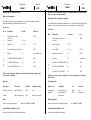
Extra items Accessoires
3129
Order No.
Airbull
3129
Réf.
Airbull
Accessoires non contenus dans la boîte de construction mais nécessaires au mon-
tage ou à la mise en œuvre du modèle.
Ensemble de radiocommande recommandé
tout ensemble robbe-Futaba à partir de quatre voies et émetteur équipé d’un dispositif de
mixage en V électronique. En particulier nous recommandons les ensembles FX 18.
Accessoires
Nbre Désignation N° de pièce réf.
1 bande adhésive double face --- 5014
(au choix)
1 bande charnière 1.4, 1.5 ---
2 servo S 3001 2.1, 2.2 F 1117
1 variateur air control 819 3.7 8611
1 récepteur 4.1 selon radio
1 accu Cd-Ni 7 P 1500 SCR AMP 4.5 4327
ou
1 accu Cd-Ni 7N 1700 SCR 4.5 4522
ou
1 accu Cd-Ni 7 N C2.4 k AMP 4.5 4614
Chargeurs, cordons de charge, outillage et accessoires de montage, cf. catalogue
général robbe.
Colles appropriées
Type de colle désignation réf. pour coller
cyanoacrylate robbe-Speed Typ 2 5063 Arcel
activateur robbe atomiseur 5017 cyanoacrylate
d’activateur
Peinture appropriée
r
obbe ro-color peintures en bombe pour Arcel réf. 55420001 - 55420017
robbe Modellsport GmbH & Co. KG
Sous réserve de modification technique
Essential items not included in the kit
Radio control equipment
Any Robbe-Futaba radio control system with 4 or more channels, with integral delta
mixer. We particularly recommend the FX-18 systems.
Accessories
No. off Description Part No. Order No.
1 Double-sided foam tape --- 5014
(to choice)
1 Hinge tape 1.4, 1.5 ---
2 S 3001 servo 2.1, 2.2 F 1117
1 Air control 819 speed controller 3.7 8611
1 Receiver 4.1 To suit RC system
1 7 P 1500 SCR AMP NC battery 4.5 4327
or
1 7 N 1700 SCR NC battery 4.5 4522
or
1 7 N C2.4 k AMP NC battery 4.5 4614
Please see the main robbe catalogue for details of battery chargers, charge leads,
tools and aids to building.
Adhesives
Type of glue Trade name Order No. Suitable for gluing
One-shot cyano glue robbe-Speed Typ 2 5063 Arcel
Activator robbe Activator spray 5017 One-shot cyano glue
Paints
r
obbe ro-color Arcel spray paints Order No. 55420001 - 55420017
robbe Modellsport GmbH & Co. KG
We reserve the right to alter technical specifications
La page est en cours de chargement...
-
 1
1
-
 2
2
-
 3
3
-
 4
4
-
 5
5
-
 6
6
-
 7
7
-
 8
8
-
 9
9
-
 10
10
-
 11
11
-
 12
12
-
 13
13
-
 14
14
-
 15
15
-
 16
16
-
 17
17
-
 18
18
-
 19
19
-
 20
20
-
 21
21


ROBBE AIRBULL 3129 Assembly And Operating Instructions Manual
- Catégorie
- Jouets télécommandés
- Taper
- Assembly And Operating Instructions Manual
dans d''autres langues
- English: ROBBE AIRBULL 3129
- Deutsch: ROBBE AIRBULL 3129
Documents connexes
-
ROBBE Slider Q Manuel utilisateur
-
ROBBE Milan Instruction And User's Manual
-
-
-
-
ROBBE Arcus Assembly And Operating Instructions Manual
-
-
-
-