ROBBE Robin DR 400 ARF Assembly And Operating Instructions Manual
- Catégorie
- Jouets
- Taper
- Assembly And Operating Instructions Manual
Ce manuel convient également à
La page est en cours de chargement...

Robin DR 400 ARF
2
Bauanleitung, Assembly instructions, Notice de montage
3048
No.
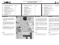
Technische Daten
Spannweite: ca. 1618 mm
Rumpflänge: ca. 1320 mm
Fluggewicht: ab 3600 g
Gesamtflächeninhalt: ca. 66,4 dm
2
Gesamtflächenbelastung: ab 55 g/dm
2
Nicht enthaltenes, jedoch erforderliches Zubehör siehe
Beilageblatt
Werkzeuge und Hilfsmittel siehe robbe Hauptkatalog
Vorwort
Vielen Dank, daß Sie sich für dieses robbe Produkt entschie-
den haben. Hierbei handelt es sich um einen ARF- (Almost
Ready to Fly) Baukasten, d.h. das Modell ist fertig gebaut und
bespannt.
Wir setzen bei diesem Modell eine gewisse Erfahrung des
Anwenders voraus und haben die nachfolgende Bauanleitung
bewußt kurz gehalten.
Einige Abschnitte sind nur angerissen und sollten vielmehr als
Wegweiser und Denkanstoß dienen.
Allgemeine Hinweise für den Bauablauf
Die Numerierung entspricht im wesentlichen der Reihenfolge
des Bauablaufs der einzelnen Baustufe, wobei die Nummer vor
dem Punkt die Baustufe, die Nummer hinter dem Punkt das
betreffende Bauteil angibt.
Verschaffen Sie sich in Verbindung mit den Abbildungen und
den dazugehörigen Kurztexten sowie den Stücklisten einen
Überblick über die jeweiligen Bauschritte.
Hinweis: Es kann vorkommen, daß bestimmte Arbeitsschritte
wie Entfernen von Bespannfolie an Klebestellen etc. bereits
ausgeführt sind. diese Schritte in dem Fall überspringen.
Die Verarbeitungsvorschriften der einzelnen Klebstoffhersteller
beachten. Alle Klebestellen gut aushärten lassen.
Richtungsangaben wie z. B. „rechts“ sind in Flugrichtung
zu sehen.
Hinweise zur Schleppkupplung (optional) finden Sie auf Seite
34.
Caractéristiques techniques
Envergure: approx. 1618 mm
Longueur du fuselage: approx. 1320 mm
Poids en ordre de vol: à partir de 3600 g
Surface alaire totale: approx. 66,4 dm
2
Charge alaire: à partir de 55 g/dm
2
Accessoires non contenus dans la boîte de construction
mais indispensables à la construction ou à la mise en
œuvre du modèle, cf. feuillet joint
Outillage et accessoires de montage, cf. catalogue général
robbe
Préface
Merci d’avoir choisi ce produit de la marque robbe. Cette boîte
de construction est de type (Almost Ready to Fly) c’est-à-dire
que le modèle est entièrement construit et entoilé.
En ce qui concerne ce modèle, nous partons du principe que
l’utilisateur dispose d’une certaine expérience ce qui explique
la brièveté de la présente notice.
Certaines sections sont simplement esquissées et doivent être
plutôt considérée comme des guides et des pense-bêtes.
Consignes générales concernant le montage
La numérotation des pièces correspond en règle générale à
leur ordre d’intervention dans la construction, le nombre devant
le point désignant le stade de montage concerné et le nombre
après le point, la pièce elle-même.
Lire attentivement la notice de construction au regard des listes
de pièces afin de se faire une vue d’ensemble du montage et
de ses diverses étapes.
À noter : il peut se produire que des opérations décrites dans
la notice, telles que le retrait du film d’entoilage à certains
endroits, soient déjà effectuées, dans ce cas, sauter la descrip-
tion concernée.
Tenir compte des prescriptions de fabricants des diverses
colles recommandées. Bien laisser durcir les points de collage.
Les données directionnelles comme gauche et droite se
rapportent au sens du vol.
Page 34, vous trouverez des indications concernant l’accou-
plement de remorquage (option).
Specification
Wingspan: approx. 1618 mm
Fuselage length: approx: 1320 mm
All-up weight: min. 3600 g
Total surface area: approx. 66.4 dm
2
Surface loading: min. 55 g/dm
2
Please see separate sheet for details of essential items not
included in the kit.
The Robbe main catalogue includes information on a wide
range of tools and aids to building.
Introduction
Congratulations on your choice of this robbe product. The
Robin is an ARF (Almost Ready to Fly) kit, i.e. the model’s com-
ponents are completely factory-built and covered. This model is
only suitable for modellers with a certain level of experience
and skill, and for this reason the building instructions have deli-
berately been kept short.
Some sections are only sketched-in, and should be considered
simply as guidelines and sources of inspiration.
Sequence of assembly
In general terms the numbering of the parts corresponds to the
sequence of assembly; the number before the point indicates
the Stage of construction, the number after the point the indi-
vidual component.
Please study the instructions, the illustrations and the parts lists
before you start building, so that you have a clear idea before-
hand of how the model goes together.
Note: you may find that some stages of construction have
already been completed, e.g. removing covering film over joint
surfaces etc. In this case simply skip that stage.
Be sure to observe the guidelines provided by the manufactur-
ers of the various adhesives you use.
Allow all glued joints to harden fully before continuing with con-
struction.
Directions such as „right-hand“ are as seen from the tail of
the model looking forward.
Please see page 34 for details of the optional aero-tow release
mechanism.

Robin DR 400 ARF
3
Bauanleitung, Assembly instructions, Notice de montage
3048
No.
Hinweis zur Stückliste: n.e. = nicht enthalten
Hinweise zur Fernsteueranlage
Orientieren Sie sich vor Baubeginn über die Einbaumöglichkeit
der zu verwendenden Fernsteueranlage.
Sollte eine andere, als die von uns vorgeschlagene
Fernsteuerung verwendet werden, so können Sie sich nach
dem Einbauschema richten. Maßdifferenzen sind allerdings
von Ihnen selbst auszugleichen.
Vor Baubeginn die Servos mit der Fernsteuerung in
Neutralstellung bringen (Knüppel und Trimmhebel am Sender
in Mittelstellung).
Hinweise zur Bespannung
Temparaturschwankungen während des Transports können zu
partiellem Verlust der Spannung der Bespannfolie führen.
Die Folie spannt sich wieder, wenn mit einem Föhn Wärme
zugeführt und die Folie glattgestrichen wird.
Baustufe 1, das Hauptfahrwerk
Nr. Bezeichnung, Maße in mm Stück
1.1 Tragflächen-Mittelteil 1
1.2 Servodeckel, Klappenservos 2
1.3 Hauptfahrwerksdrähte 2
1.4 Fahrwerkslasche 4
1.5 Blechschraube Ø 2,2 x 10 8
1.6 Rad, Ø 70 2
1.7 Stellring, Ø 4,3 innen 4
1.8 Madenschrauben M 3 x 3 4
Remarque concernant la liste des pièces:
n.c. = non contenu
Recommandations concernant la radiocommande
Avant d’entreprendre la construction du modèle, il faut être en
possession de l’ensemble de radiocommande.
Si vous installez un autre ensemble de radiocommande que
celui que nous suggérons, rectifiez par vous-mêmes les
nuances de cotes.
Avant de les mettre en place, amener les servos au neutre à
l’aide de l’ensemble de radiocommande (manche et trim corre-
spondants en position médiane).
Attention: des variations de témperature au cours du transport
sont susceptibles de provoquer une perte partielle de tension
du film de l'entoilage.
L'entoilage se retendra si vous le chauffex avec un sèche-
cheveux et le lissez.
Stade 1, l’atterrisseur principal
n° désignation, cotes en mm nbre de pièces
1.1 partie centrale de l’aile 1
1.2 couvercle de servo, servo des volets d’atterr. 2
1.3 structure métallique de l’atterrisseur principal 2
1.4 attache d’atterrisseur 4
1.5 vis autotaraudeuse Ø 2,2 x 10 8
1.6 roue, Ø 70 2
1.7 bague d’arrêt, Ø 4,3 intérieur 4
1.8 vis sans tête M 3 x 3 4
Notes on the parts list: N.I. = not included
Radio control equipment
Before you start building the model please check that your
receiving system will fit in the model as shown.
If you are using components other than the ones we recom-
mend you can still follow the basic arrangement shown, but you
may need to make allowance for minor differences in compo-
nent size.
Before you install the servos set them all to neutral from the
transmitter - sticks and trim levers central.
Notes regarding covering: tempereture variations in transport
may result in the covering film losing some of its tautness.
The film will tightn up again if you warm it with a heat gun and
smooth it down.
Stage 1, the main undercarriage
No. Description, size in mm No. off
1.1 Wing centre section 1
1.2 Flap servo well cover 2
1.3 Main undercarriage leg 2
1.4 Undercarriage saddle strap 4
1.5 Self-tapping screw, 2.2 Ø x 10 8
1.6 Wheel, 70 Ø 2
1.7 Collet, 4.3 I.D. 4
1.8 Grubscrew, M3 x 3 4
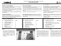
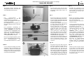
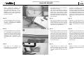
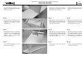
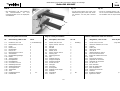
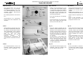
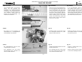
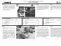
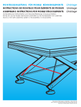
Bild 1
- Die Öffnungen an der Wurzelrippe zum
Durchziehen der Servokabel auf der
Oberseite des Tragflächen-Mittelteils
1.1 freilegen. Ebenso die Folie über
den Löchern für die
Tragflächenschrauben entfernen. Die
Brettchen mit den Nylonfäden noch
nicht lösen.
Fig. 1
- Remove the covering film over the
openings for the servo leads in the top
surface of the wing centre section 1.1
at the root. Remove the film over the
holes for the wing retainer screws at
the same time. You will see struts con-
nected to nylon threads inside the
wing; do not remove these at this
stage.
Fig. 1
- Dégager les ouvertures au niveau de
la nervure d’emplanture pour passer
les cordons des servos sur l’extrados
de la partie centrale de l’aile 1.1.
Retirer également l’entoilage sur les
trous destinés à recevoir le vis d’aile.
Ne pas défaire pour l’instant les
planchettes avec les fils de nylon.
1
1.1

Robin DR 400 ARF
4
Bauanleitung, Assembly instructions, Notice de montage
3048
No.
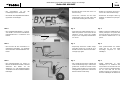
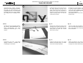
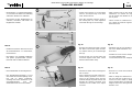
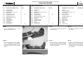
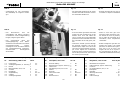
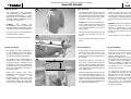
Bild 2
- Die Servodeckel 1.2 für die
Landeklappenservos abnehmen.
- Die Nut für das Hauptfahrwerk beidsei-
tig ertasten und freilegen.
Bild 3
- Die Hauptfahrwerksdrähte 1.3 einset-
zen. Die Ø 1,5 mm Löcher mit Hilfe der
Fahrwerkslaschen 1.4 markieren und
bohren.
Bild 4
- Die Laschen mit den Schrauben 1.5
probeweise befestigen, um Gewinde
einzuschneiden. Fahrwerksdrähte aus-
bauen.
Bild 5
- Die Fahrwerksdrähte 1.3 außen im
Bereich der Madenschrauben 1.8 leicht
abflachen. Die Räder 1.6 mit
Stellringen 1.7 und Madenschrauben
1.8 drehbar auf den Fahrwerksdrähten
befestigen.
Fig. 2
- Retirer les couvercles de servo 1.2 des
servos des volets d’atterrissage.
- Rechercher de chaque côté la gorge
destinée à l’atterrisseur principal et la
dégager.
Fig. 3
- Mettre la structure métallique de l’atter-
risseur principal 1.3 en place. Marquer
les trous de Ø 1,5 mm à percer à l’aide
de l’attache d’atterrisseur 1.4 et les
percer.
Fig. 4
- Fixer provisoirement les attaches à
l’aide des vis 1.5 pour tailler le
taraudage. Déposer la structure
métallique.
Fig. 5
- Aplatir légèrement la structure
métallique 1.3 à l’extérieur dans le
secteur de la vis sans tête 1.8. Fixer les
roues 1.6 avec les bague d’arrêt 1.7 et
les vis sans tête 1.8 de manière
qu’elles tournent en souplesse sur la
structure métallique de l’atterrisseur.
Fig. 2
- Remove the flap servo well covers 1.2
from the wing.
- Locate the channels for the main
undercarriage lugs on both sides and
remove the covering film over them.
Fig. 3
- Insert the main undercarriage legs 1.3.
Mark the position of the holes for the
retaining screws using the saddle
straps 1.4 as a template, and drill them
1.5 mm Ø.
Fig. 4
- Temporarily install the saddle straps
using the screws 1.5 in order to cut a
thread in the holes. Remove the under-
carriage legs again.
Fig. 5
- File a small flat area at the outside end
of the undercarriage legs 1.3 where the
grubscrews 1.8 will be located. Fit the
wheels 1.6 and collets 1.7 on the axles
and tighten the grubscrews 1.8. Ensure
that the wheels rotate freely.
4
3
Ø 1,5 mm
1.3
2
5
1.7, 1.8
1.4
1.5
1.4
1.6
(1.2)
1.3
1.3

Robin DR 400 ARF
5
Bauanleitung, Assembly instructions, Notice de montage
3048
No.
Baustufe 2, die Tragfläche
Nr. Bezeichnung, Maße in mm Stück
2.1 Servodeckel, Querruderservos 2
2.2 Tragflächenohr 2
2.3 Landeklappenservo 2 n.e.
2.4 Querruderservo 2 n.e.
2.5 Kreuzhebel 4 bei 2.3, 2.4
2.6 Servo-Verlängerungskabel 2 n.e.
2.7 Schrumpfschlauch 2 n.e.
2.8 Klötzchen 8
2.9 Blechschraube, Ø 2,2 x 6 16
2.10 Ruderhorn 4
2.11 Gabelkopf 4
2.12 Sicherungsring 4
2.13 Gestänge 4
2.14 Schraube, Ø 2,5 x 25 8
2.15 Plättchen 4
2.16 Clips 4
2.17 V-Verbinder 2
Stade 2, l’aile
n° désignation, cotes en mm nbre de pièces
2.1 couvercle de servo, servos d’aileron 2
2.2 demi-dièdre 2
2.3 servo des volets d’atterrissage 2, n.c.
2.4 servo d’aileron 2, n.c.
2.5 palonnier en croix 4, avec 2.3, 2.4
2.6 cordon-rallonge de servo 2, n.c.
2.7 gaine thermorétractable 2, n.c.
2.8 cale 8
2.9 vis autotaraudeuse, Ø 2,2 x 6 16
2.10 guignol 4
2.11 chape 4
2.12 circlips 4
2.13 tringle 4
2.14 vis, Ø 2,5 x 25 8
2.15 plaquette 4
2.16 clips 4
2.17 raccord de dièdre 2
Stage 2, the wing
No. Description, size in mm No. off
2.1 Aileron servo well cover 2
2.2 Outboard wing panel 2
2.3 Flap servo 2 N.I.
2.4 Aileron servo 2 N.I.
2.5 Cruciform output lever 4 With 2.3, 2.4
2.6 Servo extension lead 2 N.I.
2.7 Heat-shrink sleeve 2 N.I.
2.8 Servo mounting block 8
2.9 Self-tapping screw, 2.2 Ø x 6 16
2.10 Horn 4
2.11 Clevis 4
2.12 Circlip 4
2.13 Pushrod 4
2.14 Screw, 2.5 Ø x 25 8
2.15 Plate 4
2.16 Pushrod keeper 4
2.17 Dihedral brace 2
7
4 mm
Ø 2 mm
1.2, 2.1
2.2
6
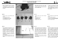
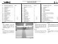
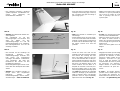
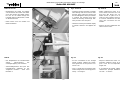
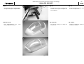
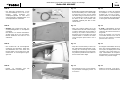
Bild 6
- Die Servodeckel 2.1 für die
Querruderservos von den
Tragflächenohren 2.2 abnehmen.
- Die Folie über den Schlitzen der
Servodeckel 1.2 und 2.1 entfernen.
Bild 7
- Die Befestigungslöcher anzeichnen
und in allen 4 Servodeckeln mit Ø 2
mm bohren.
Fig. 6
- Remove the aileron servo well covers
2.1 from the outboard wing panels 2.2.
- Remove the covering film over the
slots in the servo well covers 1.2 and
2.1.
Fig. 7
- Mark the position of the holes for the
cover retaining screws in all four servo
well covers and drill them 2 mm Ø.
Fig. 6
- Retirer ie couvercle de servo 2.1 des
servos d’aileron de la partie extérieure
des demi-dièdres de l’aile 2.2.
- Retirer l’entoilage sur les fentes des
couvercles de servo 1.2 et 2.1.
Fig. 7
- Repérer les trous de fixation et dans
tous les 4 couvercles de servo percer
avec une mèche de Ø 2.
2.1
2.2
4 mm

Robin DR 400 ARF
6
Bauanleitung, Assembly instructions, Notice de montage
3048
No.
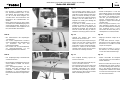
Bild 8
- Die Deckel wieder aufsetzen. Die
Auflageleisten mit Ø 1,5 mm nach den
Servodeckelbohrungen bohren.
Bild 9
- Die Steuerscheiben der
Landeklappenservos 2.3 und der
Querruderservos 2.4 entfernen.
- Servos mit beigefügten Gummitüllen
und Hülsen versehen.
- Die Kreuzhebel 2.5 beschneiden und
die äußere Bohrung auf Ø 2 mm auf-
bohren.
- Die Kreuzhebel rechtwinklig zur
Gehäuse-Längsachse auf die Servos
stecken. Beachten: Die Hebel der
Querruderservos spiegelbildlich zuein-
ander, die der Landeklappenservos
gleichsinnig zueinander aufsetzen -
siehe auch Bild 12. Hebel mit
Servohebelschrauben sichern.
- Die Servo-Verlängerungskabel 2.6 nur
an den Querruderservos anschließen.
Die Steckverbindungen mit
Schrumpfschlauchstücken 2.7 sichern.
Bild 10
- Servos auflegen und mittig zum Schlitz
ausrichten. Lage der Klötzchen 2.8
anzeichnen, Klötzchen auf die Deckel
kleben. Löcher mit Ø 1,5 mm durch die
Servoflansche in die Klötzchen bohren
und Servos festschrauben.
Fig. 8
- Place the well covers over the servo
wells. Continue the holes in the covers
through the support strips using a 1.5
mm Ø drill.
Fig. 9
- Remove the output discs from the flap
servos 2.3 and the aileron servos 2.4.
- Press the rubber grommets and metal
eyelets (supplied with the servos) into
the servo mounting lugs.
- Cut down the cruciform output levers
2.5 to the shape shown and open up
the outermost hole to 2 mm Ø.
- Fit the output arms on the servos,
checking that they are at right-angles
to the long sides of the servo case.
Note: the output arms on the aileron
servos should be a mirror-image of
each other, whereas those on the flap
servos should be on the same side –
see also Fig. 12. Fit the output screws
to retain the servo output arms.
- Connect the servo extension leads 2.6
to the aileron servos only, and shrink a
piece of heat-shrink sleeve 2.7 over
each connection to prevent them shak-
ing loose.
Fig. 10
- Place the servo on the well cover and
position the output arm in the centre of
the slot. Mark the position of the
mounting blocks 2.8, and glue the
blocks to the well cover. Drill 1.5 mm Ø
holes in the mounting blocks using the
servo mounting lugs as a template and
fit the retaining screws to secure the
servo. Repeat the procedure with the
remaining three wing-mounted servos.
Fig. 8
- Remettre les couvercles en place.
Percer les baguettes d’appui avec une
mèche de Ø 1,5 mm selon les indica-
tions fournies pas les trous des cou-
vercles de servo.
Fig. 9
- Retirer les palonniers circulaires des
servos des volets d’atterrissages 2.3 et
des servos d’aileron 2.4.
- Munir les servos des passe-fils et de
manchons joints.
- Couper les palonnier en croix 2.5 selon
les indications du schéma et porter le
trou extérieur à un Ø 2 mm.
- Planter les palonniers en croix verti-
calement par rapport à l’axe longitudi-
nal du boîtier sur les servos.
Attention: installer le palonnier des
servos d’aileron symétriquement l’un
par rapport à l’autre et celui des servos
des volets d’atterrissage dans le
même sens l’un par rapport à l’autre -
cf. également fig. 12. Fixer les palon-
niers avec les vis des servos.
- Raccorder un cordon-rallonge de
servo 2.6 uniquement aux servos
d’aileron. Munir les connecteurs de
morceaux de gaine thermorétractable
2.7.
Fig. 10
- Mettre les servos en place et les align-
er au centre sur la fente. Marquer la
position de la cale 2.8, coller la cale
sur le couvercle. Avec une mèche de Ø
1,5 mm percer des trous au travers
des flasques des servos dans la cale
et visser les servos.
2.3, 2.4
Ø 1,5 mm
2.7
2.6
2.5
8
9
10
2.8
2.1
2.4

Robin DR 400 ARF
7
Bauanleitung, Assembly instructions, Notice de montage
3048
No.
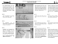
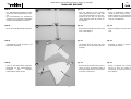
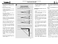
Bild 11
- Beide Landeklappenservos mit der
Fernsteuerung in die Endstellung
„Landeklappen eingefahren“ bringen.
Beide Hebel müssen sich jetzt hinten
befinden.
Bild 12
- Übersicht über die Anordnung der
Servos:
a) Querruderservo links
b) Landeklappenservo links
c) Landeklappenservo rechts
d) Querruderservo rechts
Bild 13
- Die Querruderservo-Einheiten in die
Tragflächenohren einsetzen, dabei die
Kabel nach außen führen. Servodeckel
mit Blechschrauben 2.9 montieren.
Fluchtend zu den Servohebeln und
parallel zu den Rippen die Position der
Ruderhörner auf den Querrudern
anzeichnen. Löcher mit Hilfe der
Ruderhörner markieren und mit Ø
2,5mm bohren.
Die Gestängebohrungen müssen senk-
recht über dem Drehpunkt der Ruder
stehen.
Fig. 11
- À l’aide de l’ensemble de radiocom-
mande amener les deux servos des
volets d’atterrissage en fin de course
„volets d’atterrissage escamotés“. Les
deux palonniers doivent alors se trou-
ver à l’arrière.
Fig. 12
- Vue d’ensemble de l’agencement des
servos :
a) servo d’aileron gauche
b) servo du volet d’atterrissage gauche
c) servo du volet d’atterrissage droit
d) servo d’aileron droit
Fig. 13
- Installer les unités des servos d’aileron
dans les éléments de demi-dièdre de
l’aile, en amenant les cordons vers l’ex-
térieur. Monter le couvercle de servo
avec les vis autotaraudeuses 2.9.
En ligne avec les palonniers de servo
et parallèlement aux nervures, marquer
la position des guignols sur les
ailerons. Repérer l’emplacement des
trous à percer avec les guignols et
percer les trous avec une mèche de Ø
2,5mm. Les alésages des tringles
doivent se trouver verticalement au-
dessus du pivot des gouvernes.
Fig. 11
- Move both flap servos to the “flaps
retracted” end-point from the transmit-
ter. Both output arms must now face
the tail (trailing edge).
Fig. 12
- General view of the servo arrange-
ment:
a) Left aileron servo
b) Left flap servo
c) Right flap servo
d) Right aileron servo
Fig. 13
- Place the aileron servo assemblies in
the outboard wing panels, running the
servo leads to the root. Fix the servo
well covers in place using the self-tap-
ping screws 2.9. Mark the position of
the horns on the ailerons, in line with
the servo output arms and parallel to
the ribs. Mark the hole positions
through the horn base and drill them
2.5 mm Ø.
The linkage holes in the horns must be
perpendicular to the pivot axis of the
control surface.
13
12
11
2.8
2.3
2.1
a)
b)
c)
d)
2.9
Ø 2,5 mm

Robin DR 400 ARF
8
Bauanleitung, Assembly instructions, Notice de montage
3048
No.
Bild 14
- Die Ruderhornposition auf den
Landeklappen anzeichnen und Löcher
mit Ø 2,5 mm bohren. Die
Gestängebohrungen weisen ca. 20 mm
vom Drehpunkt nach hinten. Die
Servos dazu probeweise einsetzen.
Beide Servo-Abtriebe müssen sich auf
der gleichen Seite befinden - siehe
auch Bild 12.
Bild 15
- Zwei der Ruderhörner 2.10 kürzen.
Diese Ruderhörner dienen zur
Anlenkung der Landeklappen.
Bild 16
- Die Gabelköpfe 2.11 mit
Sicherungsringen 2.12 versehen und
etwa auf halbe Gewindelänge auf die
Gestänge 2.13 aufdrehen.
Bild 17
- Gabelköpfe in den Querruderservos
einhängen. Zwei Ruderhörner 2.10
(lang) mit Schrauben 2.14 und
Plättchen 2.15 montieren. Servo in
Neutral, Ruder in Mittelstellung brin-
gen, Gestänge abwinkeln und kürzen.
Clips 2.16 zur Sicherung aufschieben.
- Auf gleiche Weise die Landeklappen
nach Zusammensetzen der
Tragfläche anschließen.
Fig. 14
- Marquer la position des guignols sur
les volets d’atterrissage et percer les
trous avec une mèche de Ø 2,5 mm.
Les alésages des tringles sont orientés
vers l’arrière à approx. 20 mm du pivot.
Pour ce faire, installer provisoirement
les servos. La transmission des deux
servos doit se trouver du même côté
pour chacun d’eux – cf. également fig.
12.
Fig. 15
- Raccourcir deux des guignols 2.10.
Ces guignols assurent l’asservisse-
ment des volets d’atterrissage.
Fig. 16
- Munir les chapes 2.11 des circlips 2.12
et les monter à mi-filetage environ sur
la tringle 2.13.
Fig. 17
- Accrocher les chapes sur les servos
d’aileron. Monter deux guignols 2.10
(longs) avec les vis 2.14 et les plaque-
ttes 2.15. À l’aide de l’ensemble de
radiocommande, amener le servo au
neutre et disposer la gouverne en posi-
tion médiame, souder et installer la
tringle. Installer le clips 2.16 pour
assurer la fixation.
- Raccorder ensuite de la même manière
les die volets d’atterrissage après
avoir assemblé l’aile.
Fig. 14
- Mark the position of the horns on the
flaps and drill the holes 2.5 mm Ø. The
linkage holes in the horns should be
offset to the rear of the flap hinge axis
by about 20 mm. Install the servos tem-
porarily to check alignment. Note that
both servo output arms must be on the
same side – see also Fig. 12.
Fig. 15
- Shorten two of the horns 2.10 as
shown. These horns are used for the
flaps.
Fig. 16
- Fit the retaining rings 2.12 on the cle-
vises 2.11 and screw them onto the
pushrods 2.13, about half-way along
the threaded length.
Fig. 17
- Connect the clevises to the aileron ser-
vos. Fix the two long horns 2.10 to the
ailerons using the screws 2.14 and
spreader plates 2.15. Check that the
servo is at neutral. Set the aileron to
centre (neutral) and mark the correct
length of the pushrod. Bend the end as
shown and snip off the excess rod
length. Push the plastic keeper 2.16
into position to secure the pushrod.
- The flap linkages are completed in a
similar way, but not until the wing pan-
els have been joined.
16
14
15
17
Ø 2,5 mm
2.10
2.11
2.12
2.16
2.13
2.13
2.16
2.14, 2.15
2.10

Robin DR 400 ARF
9
Bauanleitung, Assembly instructions, Notice de montage
3048
No.
Bild 18
- Wenn gewünscht, können die
Querruderservos ausgebaut werden.
- Die Tragflächenohren mit den V-
Verbindern 2.17 probeweise an das
Mittelteil setzen. Falls erforderlich,
nacharbeiten. Die Ohren werden nach-
einander angeklebt.
Bild 19
- Reichlich Klebstoff in den Schacht träu-
feln. Die V-Verbinder in das Mittelteil
einkleben. Übergequollenen Klebstoff
sofort abstreichen.
Bild 20
- Reichlich Klebstoff in den Schacht träu-
feln, Wurzelrippe des Tragflächenohrs
einstreichen und Ohr ansetzen. Darauf
achten, dass die Teile nicht zueinander
verwunden oder verschoben sind.
Übergequollenen Klebstoff abstrei-
chen.
Bild 21
- Den Steg “S” an welchem ein
Perlonfaden zum Durchziehen der
Servokabel befestigt ist, lösen.
Fig. 18
- Si vous le souhaitez, vous pouvez
démonter les servos d’aileron.
- Installer les demi-dièdres d’aile avec le
raccord de dièdre 2.17 provisoirement
sur la partie centrale de l’aile. Si néces-
saire, effectuer les corrections qui s’im-
posent. Les parties extérieures du
demi-dièdre seront collées successive-
ment.
Fig. 19
- Appliquer un bon bourrelet de colle
dans le logement. Coller le raccord de
dièdre dans la partie centrale de l’aile.
Retirer immédiatement l’excédent de
colle.
Fig. 20
- Appliquer un bon bourrelet de colle
dans le logement, enduire de colle la
nervure d’emplanture des demi-dièdres
et installer la partie extérieure de l’aile.
Veiller à ce que les deux parties de
l’aile ne présentent pas de gauchisse-
ment ou de décalage l’une par rapport
à l’autre. Retirer immédiatement l’excé-
dent de colle.
Fig. 21
- Défaire la traverse “S” à laquelle est
fixé le fil permettant d’installer le cordon
de servo.
Fig. 18
- The aileron servos can be removed at
this point if you prefer.
- Offer up the outboard wing panels to
the centre section using the dihedral
braces 2.17, and make any adjust-
ments required. Don’t attempt to attach
both outboard panels to the centre sec-
tion at the same time; complete each
side separately.
Fig. 19
- Apply plenty of adhesive to the inside
of the dihedral brace slot in the centre
section, and push the brace into the
slot. Wipe off excess adhesive immedi-
ately where it is squeezed out.
Fig. 20
- Apply plenty of adhesive to the inside
of the dihedral brace slot in the out-
board wing panel. Apply adhesive to
the root rib of the outboard panel at the
same time, then push the two panels
together. Ensure that the panels are not
twisted relative to each other, nor out of
line at any point. Wipe off excess adhe-
sive at the joint line.
Fig. 21
- Locate the strut “S” to which a nylon
thread is attached; this is used to draw
the servo lead through the wing.
Carefully release the strut from the
wing.
20
21
18
19
2.17
2.2
1.1
2.17
1.1
“S”

Robin DR 400 ARF
10
Bauanleitung, Assembly instructions, Notice de montage
3048
No.
Bild 22
- Querruderservos wieder einbauen,
Kabel bis zum Klappenschacht führen.
Die Kabel von Querruderservos und
Landeklappenservos am Perlonfaden
befestigen und nach innen durchzie-
hen. Klappenservos endgültig einbau-
en.
Bild 23
- Die Kabel aus den kreisrunden Öffnun-
gen ziehen. Zweckmäßigerweise die
Kabel kennzeichnen, um beim
Anschließen Verwechslungen zu ver-
meiden.
Bild 24
- Ruderhörner 2.10 (kurz) nach hinten
geneigt montieren, Gestänge der
Landeklappen anschließen.
Fig. 22
- Remonter les servos d’aileron, amener
le cordon jusqu’au logement. Fixer le
cordon des servos d’aileron et celui du
servo des volets d’atterrissage au fil et
les tirer vers l’intérieur.
Fixer définitivement le servo des volets
d’atterrissage.
Fig. 23
- Tirer les cordons des ouvertures circu-
laires. Il est rationnel de repérer les cor-
dons, pour éviter toute confusion lors
du raccordement.
Fig. 24
- Monter les guignols 2.10 (courts) avec
une inclinaison vers l’arrière, raccorder
la tringle des volets d’atterrissage.
Fig. 22
- Install the aileron servos again and run
the leads through to the flap servo
wells. Attach the aileron and flap servo
leads to the nylon line and draw it
through the wing to the opening in the
centre. The flap servos can now be
installed permanently.
Fig. 23
- Pull the servo cables out of the circular
openings at the centre of the wing. It is
a good idea to mark the leads to avoid
mixing them up when you connect
them to the receiver.
Fig. 24
- Install the short flap horns 2.10, offset
towards the trailing edge as shown,
and connect the flap pushrods.
24
22
23
2.10

Robin DR 400 ARF
11
Bauanleitung, Assembly instructions, Notice de montage
3048
No.
Baustufe 3, die Leitwerke
Nr. Bezeichnung, Maße in mm Stück
3.1 Tragflächenschraube, M 6 x 40 2
3.2 Höhenleitwerk 1
3.3 Seitenleitwerk 1
3.4 Scharnier 3
3.5 Seitenruder 1
3.6 Leitwerks-Übergang 1
3.7 Gabelkopf 3
3.8 Sicherungsring 3
3.9 Seitenrudergestänge 1
3.10 Höhenrudergestänge 2
3.11 Führungsröhrchen 3
3.12 Ruderhorn 3
3.13 Schraube, Ø 2,5 x 20 6
3.14 Plättchen 3
3.15 Seitenruderservo 1 n.e.
3.16 Höhenruderservo 1 n.e.
3.17 Kreuzhebel 1 n.e.
3.18 Sternhebel 2 n.e.
3.19 Gestängekupplung 2
3.20 Stellring mit Madenschraube 1
3.21 Clips 2
Stade 3, les empennages
n° désignation, cotes en mm nbre de pièces
3.1 vis d’aile, M 6 x 40 2
3.2 stabilisateur 1
3.3 dérive 1
3.4 charnière 3
3.5 gouverne de direction 1
3.6 passage d’empennage 1
3.7 chape 3
3.8 circlips 3
3.9 tringle de la gouverne de direction 1
3.10 tringle de la gouverne de profondeur 2
3.11 tube-guide 3
3.12 guignol 3
3.13 vis, Ø 2,5 x 20 6
3.14 plaquette 3
3.15 servo de la gouverne de direction 1, n.c.
3.16 servo de la gouverne de profondeur 1, n.c.
3.17 palonnier en croix 1, n.c.
3.18 palonnier en étoile 2, n.c.
3.19 accouplement de tringle 2
3.20 bague d’arrêt avec vis sans tête 1
3.21 clips 2
Stage 3, the tail panels
No. Description, size in mm No. off
3.1 Wing retainer screw, M6 x 40 2
3.2 Tailplane 1
3.3 Fin 1
3.4 Hinge 3
3.5 Rudder 1
3.6 Fin fairing 1
3.7 Clevis 3
3.8 Retaining ring 3
3.9 Rudder pushrod 1
3.10 Elevator pushrod 2
3.11 Pushrod sleeve 3
3.12 Horn 3
3.13 Screw, 2.5 Ø x 20 6
3.14 Spreader plate 3
3.15 Rudder servo 1 N.I.
3.16 Elevator servo 1 N.I.
3.17 Cruciform output lever 1 N.I.
3.18 Star output lever 2 N.I.
3.19 Pushrod connector 2
3.20 Collet and grubscrew 1
3.21 Pushrod keeper 2
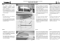
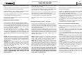
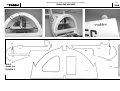
Bild 25
- Die Tragfläche mit den
Tragflächenschrauben 3.1 montieren.
Das Höhenleitwerk 3.2 aufsetzen, zur
Tragfläche ausrichten und die
Rumpfkontur beidseitig auf die
Unterseite übertragen.
Bild 26
- Die Bespannung knapp innerhalb der
Markierung entfernen. Vorsicht: Die
Beplankung darf nicht mit angeschnit-
ten werden.
Fig. 25
- Fix the wing to the fuselage using the
retaining screws 3.1. Place the
tailplane on the fuselage, align it with
the wing and mark the outline of the
fuselage on the underside of the panel
on both sides.
Fig. 26
- Remove the covering film just inside
the marked lines. Caution: take care
not to cut or score the tailplane skin.
Fig. 25
- Monter l’aile avec les vis d’aile 3.1.
Mettre le stabilisateur 3.2 en place,
pour centrer l’aile et reporter le contour
du fuselage de chaque côté sur l’intra-
dos.
Fig. 26
- Retirer l’entoilage à ras du repère.
Attention : veiller à ne pas entailler le
bois.
3.2
26
25

Robin DR 400 ARF
12
Bauanleitung, Assembly instructions, Notice de montage
3048
No.
Bild 27
- Das Höhenleitwerk aufkleben, erneut
ausrichten und Klebstoff trocknen las-
sen.
- Das Seitenleitwerk 3.3 probeweise
einsetzen und ausrichten. Klebestelle
auf dem Höhenleitwerk anzeichnen.
Bild 28
- Die Folie an der Klebestelle entfernen.
Bild 29
- Seitenleitwerk erneut einsetzen und
Klebstellen markieren.
Bild 30
- Folie an den Klebestellen entfernen.
Beidseitig an der Seitenleitwerks-
Endleiste einen schmalen
Folienstreifen stehen lassen
Fig. 27
- Glue the tailplane to the fuselage,
check alignment with the wing once
more, then allow the glue to set hard.
- Install the fin 3.3 “dry” (no glue) and
check alignment. Mark its position on
the tailplane.
Fig. 28
- Remove the covering film from the joint
area of the tailplane.
Fig. 29
- Temporarily fit the fin again and mark
the position of the joint areas with the
fuselage.
Fig. 30
- Remove the film from the joint areas as
shown. Leave a narrow strip of film at
the trailing edge of the fin on each side
as shown in the picture.
Fig. 27
- Coller le stabilisateur, l’aligner et le
centrer et laisser sécher la colle.
- Mettre la dérive 3.3 provisoirement en
place. Repérer l’emplacement du col-
lage sur la stabilisateur.
Fig. 28
- Retirer l’entoilage au niveau de l’encol-
lage.
Fig. 29
- Remonter la dérive et repérer l’em-
placement du collage.
Fig. 30
- Retirer l’entoilage des encollages.
Laisser en place une étroite bande
d’entoilage au niveau du bord de fuite
de la dérives.
27
30
29
28
3.3
3.3

Robin DR 400 ARF
13
Bauanleitung, Assembly instructions, Notice de montage
3048
No.
Bild 31
- Das Seitenleitwerk einkleben, recht-
winklig zum Höhenleitwerk ausrichten
und trocknen lassen.
Bild 32
- Die Scharniere 3.4 zur Hälfte mit Epoxy
einstreichen und in die Schlitze des
Seitenruders 3.5 einkleben – Schlitze
in Flugrichtung.
Bild 33
- Seitenleitwerkscharniere einstreichen,
Seitenruder an das Seitenleitwerk
ansetzen. Auf Leichtgängigkeit des
Ruders und ausreichende
Ruderausschläge achten.
Bild 34
- Den Leitwerks-Übergang 3.6 nach
Markierung zuschneiden.
Fig. 31
- Coller la dérive verticalement sur le sta-
bilisateur et l’aligner avant de laisser
sécher.
Fig. 32
- Enduire les charnières 3.4 jusqu’à la
moitié de colle et les coller dans la gou-
verne de direction 3.5 – les fentes se
trouvent dans le sens du vol.
Fig. 33
- Enduire les charnières de la dérive de
colle, installer la gouverne de direction
sur la dérive. Veiller à ce que la gou-
verne conserve sa souplesse et que
ses débattements soient suffisants.
Fig. 34
- Couper le passage d’empennage 3.6
en fonction des repères.
Fig. 31
- Glue the fin in place, set it exactly at
right-angles to the tailplane and leave
the glue to harden thoroughly.
Fig. 32
- Apply epoxy to half the length of the
hinges 3.4 and push them into the slots
in the rudder 3.5; the slit in the hinges
should face fore-and-aft.
Fig. 33
- Apply epoxy to the projecting part of
the rudder hinges and attach the rudder
to the fin. Remove excess glue and
check that the rudder moves freely to
both sides of neutral.
Fig. 34
- Cut out the fin fairing 3.6 along the
marked lines.
33
34
32
31
3.4
3.5
3.6

Robin DR 400 ARF
14
Bauanleitung, Assembly instructions, Notice de montage
3048
No.
Bild 35
- Den Übergang aufsetzen, möglichst
spaltfrei anpassen. Schnittkanten ver-
putzen und Übergang mit
Sekundenkleber aufkleben.
Bild 36
- Hinweis: Die Höhenruder werden ein-
zeln angelenkt.
- Die Gabelköpfe 3.7 mit den
Sicherungsringen 3.8 versehen und
etwa zur Hälfte auf das
Seitenrudergestänge 3.9 und die
Höhenrudergestänge 3.10 aufdrehen.
Die Führungsröhrchen 3.11 auf die
Gestänge schieben.
Bild 37
- Drei Schlitze für die Gestänge am
Rumpfende freilegen. Das
Seitenrudergestänge befindet sich
links hinten. Die vorbereiteten
Gestänge einschieben. Ruderhörner
3.12 einhängen. Mit Hilfe der
Ruderhörner die Löcher auf den
Ruderflächen markieren.
Die Gestängebohrungen müssen senk-
recht über dem Drehpunkt der Ruder
stehen.
- Hinweis: Die Gestänge werden im
Rumpf durch den eingebauten
Halbspant geführt. Die
Höhenrudergestänge müssen neben-
einander liegen – siehe auch Bild 38.
Fig. 35
- Mettre le passage en place, l’ajuster de
manière à ce qu’il ne présente pas de
jour. Poncer les arêtes de coupe et
colle le passage avec de la colle
cyanoacrylate.
Fig. 36
- À noter : les gouvernes de profondeur
sont asservies individuellement.
- Munie les chapes 3.7 des circlips 3.8 et
les monter à moitié environ sur la
tringle de la gouverne de direction 3.9
et sur la tringle de la gouverne de pro-
fondeur 3.10.
Glisser les tubes-guides 3.11 sur les
tringles.
Fig. 37
- Dégager trois fentes pour les tringles à
l’extrémité du fuselage. La tringle de la
gouverne de direction se trouve à
gauche à l’arrière. Enfiler les tringles
préparées. Accrocher les guignols
3.12. À l’aide des guignols, repérer
l’emplacement des trous à percer sur
les gouvernes. Les alésages des
tringles doivent se trouver verticale-
ment au-dessus du pivot des gou-
vernes.
- À noter : les tringles doivent être
passées dans le demi-couple installé.
Les tringles des gouvernes de pro-
fondeur doivent se trouver l’une à côté
de l’autre – cf. également fig. 38.
Fig. 35
- Place the fairing in position and trim it
carefully to remove any gaps. Clean up
the cut edges and glue the fairing in
place using cyano.
Fig. 36
- Note: each elevator is actuated by its
own linkage.
- Fit the retaining rings 3.8 on the clevis-
es 3.7 and screw them onto the rudder
pushrod 3.9 and elevator pushrod 3.10
to about half the threaded length. Slip
the plastic sleeves 3.11 onto the
pushrods.
Fig. 37
- Locate the three exit slots for the
pushrods at the tail end of the fuselage
and remove the covering film over
them. The rudder pushrod is the rear
one on the left-hand side. Fit the pre-
pared pushrods through the slots from
the tail end and connect the clevises to
the horns 3.12. Hold the horns on the
control surfaces and use them as a
template to mark the screw hole posi-
tions.The linkage holes in the horns
must be perpendicular to the hinge pivot
axis. Note: the pushrods are supported
inside the fuselage by the half-former
which is already in place. The elevator
pushrods must be kept immediately
adjacent to each other–see Fig. 38.
37
36
35
3.6
3.7
3.8
3.9, 3.10
3.11
3.12

Robin DR 400 ARF
15
Bauanleitung, Assembly instructions, Notice de montage
3048
No.
Bild 38
- Löcher gemäß Markierungen in die
Ruderflächen bohren, Ruderhörner
3.12 mit Schrauben 3.13 und Plättchen
3.14 montieren. Die Führungsröhrchen
nur hinten am Rumpf verkleben.
Röhrchen vorn kürzen – noch nicht
verkleben.
Bild 39
- Seitenruderservo 3.15 und
Höhenruderservo 3.16 mit beigefügten
Gummitüllen und Hülsen versehen.
Die Steuerscheiben demontieren.
Bild 40
- Einen Kreuzhebel 3.17 (Seitenruder,
Form I) und zwei Sternhebel 3.18
(Höhenruderservo und Drosselservo,
Form II) beschneiden.
Fig. 38
- Drill holes at the marked points in the
control surfaces. Install the horns 3.12
using the screws 3.13 and spreader
plates 3.14. Glue the pushrod sleeves
to the tail end of the fuselage only. Cut
the plastic sleeves to length at the front
end but do not glue them in place yet.
Fig. 39
- Press the rubber grommets and metal
eyelets into the mounting lugs of the
rudder servo 3.15 and the elevator
servo 3.16. Remove the output discs
from the servos.
Fig. 40
- Cut down one cruciform output lever
3.17 (rudder, shape I) and two star out-
put levers 3.18 (elevator and throttle
servo, shape II) as shown.
Fig. 38
- Percer les trous en fonction des
repères dans les gouvernes, monter
les guignols 3.12 avec les vis 3.13 et
les plaquettes 3.14. Ne coller les
tubes-guides qu’à l’arrière au fuselage.
Raccourcir les tubes – ne pas les coller
pour l’instant.
Fig. 39
- Munir le servo de la gouverne de direc-
tion 3.15 et le servo de la gouverne de
profondeur 3.16 des passe-fils et des
manchons joints. Démonter les palon-
niers circulaires.
Fig. 40
- Couper palonnier en croix 3.17 (gou-
verne de direction, aspect I) et deux
palonniers en étoile 3.18 (servo de la
gouverne de profondeur et servo des
gaz, aspect II).
40
39
38
3.12
3.13, 3.14
3.11
3.11
3.11
3.15, 3.16
3.17
3.18
I
II

Robin DR 400 ARF
16
Bauanleitung, Assembly instructions, Notice de montage
3048
No.
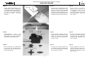
Bild 41
- Gestängekupplungen 3.19 je an einem
beschnittenen Kreuzhebel und
Sternhebel drehbar montieren. Die
Mutter mit Sekundenkleber sichern.
Bild 42
- Servos 3.15 und 3.16 einbauen, in
Neutralstellung bringen, Kreuzhebel
und beschnittenen Sternhebel (ohne
Kupplung) montieren.
Bild 43
- Ein Höhenrudergestänge zurechtbie-
gen und kürzen, sodaß die Gestänge
mit dem Stellring 3.20 zusammenge-
faßt werden können.
- Die Gestänge über der Bohrung des
jeweiligen Kreuzhebels markieren
(Ruder in Mittelstellung). Gestänge
aushängen, ein Stück nach vorn zie-
hen, abwinkeln und kürzen.
- Gestänge mit Clips 3.21 versehen und
in den Kreuzhebeln einhängen.
- Die Führungsröhrchen am Halbspant
verkleben.
- Die Detaildarstellungen zeigen die
Gestänge außerhalb des Rumpfs
Fig. 41
- Monter les accouplements de tringle
3.19 chaque fois à un palonnier en
croix coupé et un palonnier en étoile de
manière à conserver leur souplesse.
Bloquer les écrous avec de la colle
cyanoacrylate.
Fig. 42
- Monter les servos 3.15 et 3.16, les
amener au neutre à l’aide de l’ensem-
ble de radiocommande, monter le
palonnier en croix et le palonnier en
étoile coupé (sans accouplement).
Fig. 43
- Couder et raccourcir une tringle de la
gouverne de profondeur, de sorte que
les tringles puissent être réunies dans
la bague d’arrêt 3.20.
- Marquer la tringle au-dessus de
l’alésage du palonnier en croix con-
cerné (les gouvernes sont en position
médiane). Décrocher la tringle, tirer un
morceau vers l’avant, couder et rac-
courcir.
- Munir la tringle de clips 3.21 et l’ac-
crocher dans le palonnier en croix.
- Coller les tubes-guides au demi-cou-
ple.
- Les représentations de détail présen-
tent les tringles à l’extérieur du fuse-
lage
Fig. 41
- Mount the pushrod connectors 3.19 on
two of the prepared output arms (one
cruciform, one star). Check that they
rotate smoothly, without slop, then
apply a drop of cyano to the retaining
nuts.
Fig. 42
- Install the servos 3.15 and 3.16, set
them to neutral from the transmitter and
fit the trimmed cruciform and star out-
put arms (without pushrod connector)
on them as shown.
Fig. 43
- Bend one elevator pushrod to the
shape shown and shorten it so that the
pushrods can be joined together using
the collet 3.20.
- Set the tail control surfaces to centre
and mark the point at which the
pushrods cross the holes in the output
arms. Disconnect the pushrods at the
tail end so that you can pull them for-
ward slightly. Bend the pushrods at the
marked points and snip off excess rod
length.
- Fit the plastic keepers 3.21 on the
pushrods and connect them to the
servo output arms.
- Glue the guide tubes to the half-former.
- The detail drawings show the pushrods
removed from the fuselage.
42
41
3.16
3.15
3.17
3.21
3.15
3.16
3.20
3.21
3.10
3.21
3.9
43
3.20
3.19
3.18

Baustufe 4, Vorbereiten des Rumpfkopfs
Nr. Bezeichnung, Maße in mm Stück
4.1 Bugfahrwerkslager 1
4.2 Schraube, M 3 x 20 4
4.3 Zahnscheibe, Ø 3,2 innen 4
4.4 Unterlegscheibe, Ø 3,2 innen 4
4.5 Mutter, M 3 4
4.6 Röhrchen, Bugfahrwerksgestänge 1
4.7 Röhrchen, Drosselgestänge 1
4.8 Schraube, M 4 x 25 4
4.9 Fächerscheibe, Ø 4,2 4
4.10 Unterlegscheibe, Ø 4,2 4
4.11 Motorträger 2
Robin DR 400 ARF
17
Bauanleitung, Assembly instructions, Notice de montage
3048
No.
Stade 4, préparatifs au nez du fuselage
n° désignation, cotes en mm nbre de pièces
4.1 palier de l’atterrisseur avant 1
4.2 vis, M 3 x 20 4
4.3 rondelle à dents, Ø 3,2intérieur 4
4.4 rondelle, Ø 3,2 intérieur 4
4.5 écrou, M 3 4
4.6 tube, tringle de l’atterrisseur avant 1
4.7 tube, tringle des gaz 1
4.8 vis, M 4 x 25 4
4.9 rondelle éventail, Ø 4,2 4
4.10 rondelle, Ø 4,2 4
4.11 support-moteur 2
Stage 4, preparing the fuselage nose
No. Description, size in mm No. off
4.1 Noseleg mount 1
4.2 Screw, M3 x 20 4
4.3 Shakeproof washer, 3.2 I.D. 4
4.4 Plain washer, 3.2 I.D. 4
4.5 Nut, M3 4
4.6 Noseleg pushrod sleeve 1
4.7 Throttle pushrod sleeve 1
4.8 Screw, M4 x 25 4
4.9 Serrated washer, 4.2 Ø 4
4.10 Plain washer, 4.2 Ø 4
4.11 Motor mount 2
Bilder 44 und 45
- Es empfiehlt sich, jetzt den Kopfspant
und den Tankraum mit Porenfüller oder
Klarlack gegen Kraftstoffeinflüsse zu
imprägnieren.
- Das Bugfahrwerkslager 4.1 mit
Schrauben 4.2, Zahnscheiben 4.3,
Unterlegscheiben 4.4 und Muttern 4.5
am eingebauten Zwischenspant mon-
tieren.
- Die Führungsröhrchen 4.6 für das
Bugfahrwerksgestänge und 4.7 für das
Drosselgestänge ablängen und ein-
schieben – noch nicht verkleben.
Bild 46
- Schrauben 4.8 mit Fächerscheiben 4.9
und Unterlegscheiben 4.10 versehen.
46
45
44
Figs. 44 and 45
- We recommend that you fuel-proof the
nose bulkhead and fueltank compart-
ment at this point to prevent the sur-
faces absorbing fuel. Use sanding
sealer or clear fuel-proofer for this.
- Attach the noseleg mount 4.1 to the
factory-fitted secondary bulkhead
using the screws 4.2, shakeproof
washers 4.3, plain washers 4.4 and
nuts 4.5.
- Cut to length the plastic sleeves 4.6 for
the noseleg pushrod and 4.7 for the
throttle pushrod and fit them through
the former – don’t glue them at this
stage.
Fig. 46
- Fit the serrated washers 4.9 and plain
washers 4.10 on the screws 4.8.
Fig. 44 et 45
- Il est recommandé, à ce stade du mon-
tage, de traiter le couple avant et le
logement du réservoir avec du
bouche-pores ou un vernis transparent
afin de les protéger des projections de
carburant.
- Monter le palier de l’atterrisseur avant
4.1 avec les vis 4.2, les rondelles à
dents 4.3, les rondelle 4.4 et les
écrous 4.5 sur le couple intermédiaire
installé.
- Couper et introduite le tube-guide 4.6
faisant office de tringle de l’atterrisseur
avant et 4.7 faisant office de tringle des
gaz
– Ne pas les coller pour l’instant.
Fig. 46
- Munir les vis 4.8 des rondelles éventail
4.9 et des rondelles 4.10.
4.1
4.2
4.3
4.4
4.5
4.6
4.7
4.8
4.9
4.10
4.11

Robin DR 400 ARF
18
Bauanleitung, Assembly instructions, Notice de montage
3048
No.
Bild 47
- Die Motorträger 4.11 mit Schrauben
4.8, Fächerscheiben 4.9 und
Unterlegscheiben 4.10 am Kopfspant
verschrauben.
Fig. 47
- Fix the motor mount 4.11 to the nose
bulkhead using the screws 4.8, serrat-
ed washers 4.9 and plain washers
4.10.
Fig. 47
- Visser les supports-moteur 4.11 avec
les vis 4.8, les rondelles éventail 4.9 et
les rondelles 4.10 au couple avant.
47
Baustufe 5, Bugfahrwerk und Tank
Nr. Bezeichnung, Maße in mm Stück
5.1 Radachse, M 3 x 60 1, Gewindestange
5.2 Distanzhülse, Ø 4 x 34 1
5.3 Halter 2
5.4 Mutter, M 3 4
5.5 Bugfahrwerk 1
5.6 Rad, Ø 70 1
5.7 Distanzbuchse, Ø 8 x 5 2
5.8 Anlenkhebel 1
5.9 Bugfahrwerksgestänge 1
5.10 Mutter 1
5.11 Tankverschluß 1
5.12 Deckplättchen 1
5.13 Deckplättchen 1
5.14 Schraube, M 3 x 20 1
5.15 Belüftungsröhrchen 1
5.16 Zuleitungsröhrchen 1
5.17 Ansaugschlauch 1
5.18 Tankpendel 1
5.19 Tank 1
5.20 Kraftstoffschlauch 2 n.e.
5.21 Kabelbinder 1
Stage 5, noseleg and fueltank
No. Description, size in mm No. off
5.1 Wheel axle, M3 x 60 1 Studding
5.2 Spacer sleeve, 4 Ø x 34 1
5.3 Axle lug 2
5.4 Nut, M3 4
5.5 Noseleg unit 1
5.6 Wheel, 70 Ø 1
5.7 Spacer sleeve, 8 Ø x 5 2
5.8 Steering arm 1
5.9 Noseleg pushrod 1
5.10 Nut 1
5.11 Fueltank stopper 1
5.12 Stopper end-plate 1
5.13 Stopper end-plate 1
5.14 Screw, M3 x 20 1
5.15 Vent pipe 1
5.16 Feed pipe 1
5.17 Pick-up tube 1
5.18 Fueltank clunk weight 1
5.19 Fueltank 1
5.20 Fuel tubing 2 N.I.
5.21 Cable tie 1
Stade 5, l’atterrisseur avant et le réservoir
n° désignation, cotes en mm nbre de pièces
5.1 axe de roue, M 3 x 60 1, tige filetée
5.2 manchon entretoise, Ø 4 x 34 1
5.3 support 2
5.4 écrou, M 3 4
5.5 atterrisseur avant 1
5.6 roue, Ø 70 1
5.7 douille-entretoise, Ø 8 x 5 2
5.8 levier d’asservissement 1
5.9 tringle de l’atterrisseur avant 1
5.10 écrou 1
5.11 bouchon de réservoir 1
5.12 plaquette de couverture 1
5.13 plaquette de couverture 1
5.14 vis, M 3 x 20 1
5.15 tube d’aération 1
5.16 tube de remplissage 1
5.17 tube d’aspiration 1
5.18 plongeur du réservoir 1
5.19 réservoir 1
5.20 flexible à carburant 2, n.c.
5.21 ligature de câbles 1
4.11
4.8
4.9, 4.10
4.7

Robin DR 400 ARF
19
Bauanleitung, Assembly instructions, Notice de montage
3048
No.
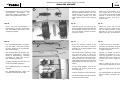
Bilder 48 und 49
- Die Radachse 5.1 mit der Distanzhülse
5.2 versehen. Die Halter 5.3 beidseitig
aufstecken. Muttern 5.4 aufdrehen.
- Die Einheit auf das Bugfahrwerk 5.5
schieben, ausrichten und Halter am
Bugfahrwerk verlöten.
Bild 50
- Radachse ausbauen. Das Rad 5.6 und
die Distanzbuchsen 5.7 aufschieben,
Rad einbauen.
- Die Muttern 5.4 beidseitig aufdrehen
und jeweils gegeneinander kontern.
Das Rad muß frei drehbar bleiben.
Bild 51
- Den Anlenkhebel 5.8 einseitig kürzen.
- Das Bugfahrwerksgestänge 5.9 auf
einer Seite mit einer Z-Kröpfung verse-
hen und im Hebel einhängen.
Gestänge durch das Röhrchen in die
Gestängekupplung 3.19 des
Seitenruderservos 3.15 einschieben.
Fig. 48 et 49
- Munir l’axe de roue 5.1 des manchons
entretoises 5.2. Planter les supports
5.3 de chaque côté. Mettre les écrous
5.4 en place.
- Glisser l’unité sur l’atterrisseur avant
5.5, l’aligner et souder le support à l’at-
terrisseur avant.
Fig. 50
- Démonter l’axe de roue. Enfiler la roue
5.6 et les douille-entretoises 5.7, mon-
ter la roue.
- Installer les écrous 5.4 de chaque côté
et contrer bilatéralement.
La roue doit tourner avec souplesse.
Fig. 51
- Raccourcir le levier d’asservissement
5.8 d’un côté.
- Munir la tringle de l’atterrisseur avant
5.9 d’un côté d’un coude en Z et l’ac-
crocher au levier. Enfiler la tringle au
travers du tube dans l’accouplement de
tringle 3.19 du servo de la gouverne de
direction 3.15.
Figs. 48 and 49
- Fit the spacer sleeve 5.2 on the wheel
axle 5.1, and slip the lugs 5.3 on both
ends. Fit the nuts 5.4.
- Push this assembly onto the ends of
the noseleg unit 5.5, check alignment
and solder the lugs to the noselegs.
Fig. 50
- Remove the wheel axle again. Thread
the wheel 5.6 and the spacer sleeves
5.7 onto the axle as you re-fit it through
the lugs.
- Screw the nuts 5.4 on both sides and
lock them against each other. Check
that the wheel rotates freely.
Fig. 51
- Shorten one shank of the steering lever
5.8 as shown.
- Form a Z-bend in one end of the nose-
wheel steering pushrod 5.9 and con-
nect it to the steering lever. Slip the
pushrod through the plastic sleeve and
through the pushrod connector 3.19
mounted on the rudder servo output
arm 3.15.
50
51
49
48
5.1
5.2
5.3
5.4
5.5
5.6
5.7
5.8
5.10
5.1, 5.2
5.7
5.4
5.8
5.9

Robin DR 400 ARF
20
Bauanleitung, Assembly instructions, Notice de montage
3048
No.
Bilder 52 und 53
- Bugfahrwerk mit Hebel und Mutter
5.10 einsetzen. Die Feder muß dabei
nach vorn weisen. Die Mutter aufdre-
hen, bis sie am Hebel anliegt. Das
Fahrwerk jetzt um 180° drehen, sodaß
es fühlbar einrastet.
- Hebel etwas nach vorn stellen und
Mutter festziehen.
Bild 54
- Das Bugfahrwerk auf Geradeauslauf
stellen. Inbusschraube der
Gestängekupplung 3.19 anziehen.
- Zweckmäßigerweise wird jetzt das
Hauptfahrwerk endgültig an der
Tragfläche montiert – siehe auch
Baustufe 1.
Figs. 52 and 53
- Install the noseleg assembly, complete
with steering lever and nut 5.10. Note
that the spring must face forward. Fit
the nut and tighten it to the point where
it contacts the steering lever. Now
rotate the noseleg unit through 180°
until you feel it click into place.
- Offset the steering arm forward slightly
to provide clearance and tighten the
nut.
Fig. 54
- Set the nosewheel to the “straight
ahead” position. Tighten the socket-
head grubscrew in the pushrod con-
nector 3.19.
- This is a good time to install the main
undercarriage units in the wing perma-
nently – see Stage 1.
Fig. 52 et 53
- Mettre l’atterrisseur avant en place
avec le levier et l’écrou 5.10. Le ressort
doit alors être dirigé vers l’avant.
Mettre l’écrou en place et le visser
jusqu’à ce qu’il s’appuie contre le levi-
er. Tourner l’atterrisseur de 180° de
sorte qu’il s’enclenche de manière
audible.
- Agencer le levier légèrement vers l’a-
vant et serrer l’écrou.
Fig. 54
- Disposer l’atterrisseur avant sur une
trajectoire rectiligne. Serrer la vis six
pans creux de l’accouplement de
tringle 3.19.
- Il est rationnel de monter maintenant
l’atterrisseur principal définitivement
sur l’aile – cf. stade 1.
54
52
53
5.8
5.10
5.9
5.10
3.19
5.9

Robin DR 400 ARF
21
Bauanleitung, Assembly instructions, Notice de montage
3048
No.
Bilder 55 und 56
- Den Tankverschluß 5.11 mit den
Deckplättchen 5.12, 5.13 versehen,
Schraube 5.14 eindrehen, nicht anzie-
hen. Belüftungsröhrchen 5.15 ein-
schieben; hinteres Röhrchenende
nach oben biegen.
- Das Zuleitungsröhrchen 5.16 einschie-
ben.
- Ansaugschlauch 5.17 aufschieben,
kürzen und mit dem Tankpendel 5.18
versehen.
Bild 57
- Tankverschluß in den Tank 5.19 schie-
ben. Durch Schwenken des Tanks prü-
fen, daß das Pendel in keiner Lage im
Tank hängenbleibt. Sonst Schlauch
5.17 kürzen. Schraube 5.14 anziehen.
- Zwei ca. 200 mm lange
Kraftstoffschläuche 5.20 auf die
Röhrchen schieben. Den
Ansaugschlauch (Tankpendel) mit
einem Streifen Isolierband kennzeich-
nen.
Bild 58
- Die Kraftstoffschläuche durch den
Kopfspant schieben, Tank einsetzen
und mit einem Kabelbinder 5.21
sichern.
Figs. 55 and 56
- Hold the circular end-plates 5.12 / 5.13
on either side of the fueltank stopper
5.11 and fit the screw 5.14 to hold them
in position; don’t tighten the screw at
this stage. Fit the vent pipe 5.15
through the stopper and bend the rear
end of the pipe upwards.
- Push the fuel feed pipe 5.16 through
the stopper.
- Push the clunk tube 5.17 onto the feed
pipe, cut it to length and fit the clunk
pick-up 5.18 on the other end.
Fig. 57
- Push the stopper assembly into the
fueltank 5.19 and swivel the tank in all
directions to check that the clunk pick-
up does not get caught or hung up at
any point in the tank. If it does, shorten
the fuel pick-up tube 5.17. Tighten the
screw 5.14 to seal the tank when you
are satisfied.
- Cut two pieces of fuel tubing 5.20
about 200 mm long and push them
onto the projecting metal tubes. Wrap
a strip of coloured insulating tape
round the fuel feed line (clunk pick-up)
to avoid confusion later.
Fig. 58
- Thread the fuel tubes through the nose
bulkhead. Install the fueltank and
secure it with the cable tie 5.21.
Fig. 55 et 56
- Munir le bouchon du réservoir 5.11 des
plaquettes de couverture 5.12, 5.13,
installer la vis 5.14 sans serrer pour
l’instant.
Enfiler le tube d’aération 5.15; couder
l’extrémité arrière du tube vers le haut.
- Mettre le tube de remplissage 5.16 en
place.
- Mettre le tube d’aspiration 5.17 en
place, le raccourcir et le munir du
plongeur du réservoir 5.18.
Fig. 57
- Glisser le bouchon du réservoir dans le
réservoir 5.19. En faisant pivoter le
réservoir, vérifier que le plongeur ne
reste pas accroché dans le réservoir,
quelle que soit sa position. Sinon, rac-
courcir le flexible 5.17. Serrer la vis
5.14.
- Glisser deux flexibles 5.20 à carburant
d’approx. 200 mm de long sur les
tubes. Repérer le tube d’aspiration
(plongeur du réservoir) avec un
morceau de ruban isolant.
Fig. 58
- Passer les flexibles à carburant dans
le couple avant, mettre le réservoir en
place et le fixer avec une ligature de
câbles 5.21.
58
57
56
55
5.11
5.12
5.13
5.14
5.15
5.16
5.18
5.19
5.17
5.11-5.18
5.19
5.20
5.21
La page est en cours de chargement...
La page est en cours de chargement...
La page est en cours de chargement...
La page est en cours de chargement...
La page est en cours de chargement...
La page est en cours de chargement...
La page est en cours de chargement...
La page est en cours de chargement...
La page est en cours de chargement...
La page est en cours de chargement...
La page est en cours de chargement...
La page est en cours de chargement...
La page est en cours de chargement...
La page est en cours de chargement...
La page est en cours de chargement...
-
 1
1
-
 2
2
-
 3
3
-
 4
4
-
 5
5
-
 6
6
-
 7
7
-
 8
8
-
 9
9
-
 10
10
-
 11
11
-
 12
12
-
 13
13
-
 14
14
-
 15
15
-
 16
16
-
 17
17
-
 18
18
-
 19
19
-
 20
20
-
 21
21
-
 22
22
-
 23
23
-
 24
24
-
 25
25
-
 26
26
-
 27
27
-
 28
28
-
 29
29
-
 30
30
-
 31
31
-
 32
32
-
 33
33
-
 34
34
-
 35
35
-
 36
36


ROBBE Robin DR 400 ARF Assembly And Operating Instructions Manual
- Catégorie
- Jouets
- Taper
- Assembly And Operating Instructions Manual
- Ce manuel convient également à
dans d''autres langues
- English: ROBBE Robin DR 400 ARF
- Deutsch: ROBBE Robin DR 400 ARF
Documents connexes
-
ROBBE RAT Instruction And User's Manual
-
ROBBE Twister 3121 Assembly And Operating Instructions Manual
-
ROBBE Air Beaver Assembly And Operating Instructions Manual
-
-
-
-
-
ROBBE 2638 Instruction And User's Manual
-
-
Autres documents
-
 Hangar 9 HAN3185 Le manuel du propriétaire
-
MULTIPLEX MPU13209 Manuel utilisateur
-
MULTIPLEX Funcub Le manuel du propriétaire
-
HiTEC MiniMag RR Le manuel du propriétaire
-
 Nu-Vu Food Service System OP-3/9M Fiche technique
-
 Ecotop BIDULE 55 Manuel utilisateur
-
SKYLOTEC CS2 Instructions For Use Manual
-
Westinghouse iGenTent Manuel utilisateur
-
Equipex EP800 Le manuel du propriétaire
-
 Stageworx UniStage 2,0 x 1,0m IDSC Mode d'emploi


