ROBBE Bucker Jungmeister 3041 Assembly And Operating Instructions Manual
- Catégorie
- Jouets télécommandés
- Taper
- Assembly And Operating Instructions Manual
La page est en cours de chargement...

Bücker Jungmeister
3
Bauanleitung, Assembly instructions, Notice de montage
3041
No.
Technische Daten
Spannweite: ca. 790 mm
Gesamtflächeninhalt: ca. 23 dm
2
Fluggewicht: ca. 300 g
Nicht enthaltenes Zubehör siehe Beilageblatt
Werkzeuge und Hilfsmittel siehe robbe Hauptkatalog
Allgemeine Hinweise für den Bauablauf
Die Numerierung entspricht im wesentlichen der Reihenfolge
des Bauablaufs.
Verschaffen Sie sich in Verbindung mit den Abbildungen und
Kurztexten einen Überblick über die jeweiligen Bauschritte.
Das Auffinden der Stanzteile erleichtern die Identifikations-
Zeichnungen auf Seite 4.
Verklebungen von Styropor
Klebearbeiten an Styroporteilen nur mit Weißleim oder Epoxy
ausführen.
Kleber auf Nitro- und Polyesterbasis und Sekundenkleber
führen zur Zerstörung des Werkstoffs.
Zum Verkleben von Kunststoffteilen mit Styropor ausschließ-
lich Epoxy verwenden.
Epoxy-Kleber aus Gewichtsgründen sparsam aber gleichmä-
ßig verteilt aufbringen.
Richtungsangaben wie z. Bsp. „rechts“ sind in Flugrich-
tung zu sehen.
Hinweise zur Fernsteueranlage
Als Fernsteuerung benötigen Sie eine Anlage mit 4 Kanälen
und 2 Servos sowie einen elektronischen Flugregler.
Orientieren Sie sich vor Baubeginn über die Einbaumöglich-
keit der zu verwendenden Fernsteuerung.
Sollte eine andere, als die von uns vorgeschlagene
Steuerung verwendet werden, können Sie sich nach dem
Einbauschema richten.
Maßdifferenzen sind von Ihnen selbst auszugleichen.
Caractéristiques techniques
Envergure 790 mm environ
Surface alaire totale 23 dm
2
environ
Poids en ordre de vol 300 g environ
Accessoires non contenu dans la boîte de construction,
cf. le feuillet joint
Outillage et accessoires de montage, cf. Catalogue
général robbe
Recommandations générales concernant la construction
La numérotation correspond en règle générale à l’ordre de la
construction.
Avant d’entreprendre la construction, lire attentivement les
textes explicatifs en vous reportant aux illustrations afin de
vous faire une idée d’ensemble de l’ordre des séquences
d’assemblage.
L’identification des pièces estampées est facilitée par les
schémas du page 4.
Collage du styropor
Les opérations de collage ne seront réalisées qu’avec de la
colle blanche ou de la colle époxy.
Les colles à base de nitrée ou polyester et les colles cyano-
acrylates entraînent une destruction du matériau.
Pour coller des éléments de plastique avec des pièces en
styropor, utiliser exclusivement de la colle époxy.
Pour des raisons d’économie de poids, appliquer la colle
époxy parcimonieusement mais en la distribuant de manière
homogène.
Les données directionnelles comme «droite», par exem-
ple, sont à considérer dans le sens du vol.
Recommandations concernant l’ensemble de radiocom-
mande
Il faut, pour le modèle, un ensemble de radiocommande de
quatre voies avec 2 servos et un variateur électronique.
Avant de commencer l’assemblage reporter les cotes en
fonction de l’ensemble de radiocommande utilisé.
Si vous utilisez un autre ensemble de radiocommande que
celui que nous recommandons, suivre les indications
fournies par les illustrations.
Rectifiez par vous-même les différences de cote éventuelles.
Specification
Wingspan: approx. 790 mm
Total flying surface area: approx. 23 dm
2
All-up weight: approx. 300 g
See separate sheet for details of essential items not
included in the kit.
Please refer to the main robbe catalogue for details of
tools and aids to building.
Sequence of assembly
In general terms the numbering of the kit components corre-
sponds to the sequence of assembly.
Please study the illustrations and instructions before you
start building, so that you have a clear idea from the outset
how the model goes together.
The identification drawings on page 4 are designed to help
you locate and identify the die-cut parts.
Adhesives and styrofoam
Styrofoam parts should be glued together using either white
glue or epoxy only.
Never allow cellulose-based, polyester or cyano-acrylate
adhesives to contact the styrofoam parts, as they will attack
and destroy the material.
Use epoxy for gluing all plastic parts to styrofoam.
When you have to use epoxy apply it sparingly and distrib-
ute it evenly, otherwise you can easily add excessive weight.
Directions such as „right-hand“ are as seen from the tail
of the model looking forward.
Radio control system
You will need a 4-channel radio control system with two ser-
vos and an electronic speed controller.
Before you start construction check that your RC system
components can be fitted in the position shown in the draw-
ings.
If you intend to fit an RC system other than the one we rec-
ommend, you can still follow the basic arrangement shown,
but you may have to make allowance for slight differences in
component size.

Bücker Jungmeister
4
Bauanleitung, Assembly instructions, Notice de montage
3041
No.
6
15
15
2
3
4
20
7
1
35
35
14
9
10
8
8
11
Hinweise zu den Dekorbildern
- Die Dekorbilder können nach eigenem Ermessen aufge-
bracht werden.
- Wir empfehlen dies, bevor die Einzelteile am Modell be-
festigt werden.
- Jedes Abziehbild - Motiv einzeln ausschneiden und ca.
60 sec. in Wasser eintauchen. Tip: Die Haftung der
Abziehbilder wird deutlich erhöht, wenn auf die betref-
fende Stelle am Modell stark verdünnter Weißleim
aufgetragen wird. Das Motiv an der bezeichneten Stelle
vom Papier abschieben und mit Löschpapier andrücken.
- Erst dann die obere weisse Trägerfolie entfernen.
Recommandations concernant l’application des trans-
ferts.
- Disposer les transferts selon vos goûts sur le modèle.
- Nous vous conseillons de les appliquer sur les éléments du
modèle avant de mettre ceux-ci en place.
- Découper chacun des transferts et les tremper approxima-
tivement 60 secondes dans l’eau. Un conseil : l’adhérence
des transferts est nettement améliorée lorsque les
emplacements du modèle sur lesquels ils sont appliqués
sont préalablement enduits de colle cellulosique diluée.
Appliquer le motif du transfert à l’emplacement choisi et le
décoller du papier avant de le tamponner avec un buvard.
- Retirer ensuite seulement le film blanc de surface.
Notes on the water-slide decals
- The decals can be applied in any arrangement you find
pleasing.
- We recommend that you apply them before the model’s
components are assembled.
- Cut out each individual decal and place it in water for
about 60 seconds. Tip: the decals adhere much more
strongly if a coat of highly thinned white glue is applied
to that area of the model beforehand and allowed to dry.
Slide the decal off the paper and into position, and press
down gently using blotting paper.
- Do not remove the top backing film until this stage.
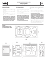
ID-Stanzteile
Identification drawing for die-cut parts
Fig. d'identification des pièces estampées
22
La page est en cours de chargement...
La page est en cours de chargement...

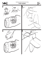
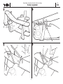
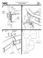
Fig. 1
- Coller le renfort 1 sur le couple moteur 2.
Fig. 2
- Coller les couples 4 - 4 dans le fuselage 5. Si nécessaire,
les poncer légèrement au préalable. La position des cou-
ples dans le fuselage est donnée par les concavités.
- Le couple moteur _ doit être collé avec un piqueur de 2°
approx. et un anticouple de 2° vers la droite.
Fig. 3
- Entailler les fentes pour les traverses d’aile et d’atterris-
seur selon les repères avec un couteau bien aiguisé ou
une lame de rasoir. Utiliser les fentes du couple 3 comme
guide pour le couteau.
Fig. 4
- Coller le support-servo 6 et la platine du récepteur 7 dans
le fuselage.
Bücker Jungmeister
7
Bauanleitung, Assembly instructions, Notice de montage
3041
No.
Fig. 1
- Glue the plywood doubler 1 to the motor bulkhead 2.
Fig. 2
- Check that formers 2 - 4 fit in the fuselage 5, and sand
them slightly if necessary. Glue the formers inside the
fuselage. The position of the formers inside the fuselage
is indicated by notches moulded into the inside surfaces.
- Note that the front former has to be angled slightly to pro-
vide about 2° of right side-thrust and down-thrust.
Fig. 3
- Cut the slots for the wing struts and undercarriage legs at
the marked points using a sharp knife or razor blade.
Use the slots in the formers as a guide for the blade.
Fig. 4
- Glue the servo plate 6 and the receiver plate 7 in the
fuselage.
Bild 1
- Aufdopplung 1 auf den Motorspant 2 kleben.
Bild 2
- Die Spanten 2 - 4 in den Rumpf 5 kleben. Wenn nötig,
Spanten vorher leicht überschleifen. Die Position der
Spanten im Rumpf ist durch Anformungen vorgegeben.
- Der Motorspant 1/2 muß mit ca. 2° Sturz und 2°
Seitenzug nach rechts eingeklebt werden.
Bild 3
- Die Schlitze für Tragflächen- und Fahrwerksstreben mit ei-
nem scharfen Messer oder einer Rasierklinge nach Mar-
kierungen ausschneiden. Die Schlitze im Spant 3 dabei
als Führung für das Messer verwenden.
Bild 4
- Servo-Halteplatte 6 und Empfängerplatte 7 in den Rumpf
kleben.
La page est en cours de chargement...

Bücker Jungmeister
9
Bauanleitung, Assembly instructions, Notice de montage
3041
No.
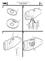
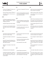
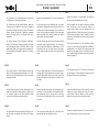
Bild 5
- Aus den Teilen 8 - 11 die Akkubox zusammenkleben.
Fertige Akkubox zwischen Servo-Halteplatte 6 und
Spant 3 im Rumpf verkleben.
Bild 6
- Höhen- und Seitenruder 12 und 13 ansetzen. Spalt "S"
anschleifen. Über die Kanten ohne Spalt jeweils einen
Streifen Klebeband als Ruderscharnier "R" spannen. Die
Ruder mehrfach hin- und herbewegen, um die Leicht-
gängigkeit zu gewährleisten.
Bild 7
- Die Klebebilder beidseitig auf das Seitenruder kleben.
- Ruderhörner 14 mit 1 mm bohren und in eingeschnittene
Schlitze der Ruder 12 und 13 einkleben.
Bild 8
- Höhen- und Seitenleitwerk 12, 13 rechtwinklig zusam-
menkleben. Einheit in den Rumpf kleben. Auf korrekten
Sitz achten.
Fig. 5
- Assemble the battery box from parts 8 - 11.
- Glue the completed battery box between the servo plate 6
and former 3.
Fig. 6
- Sand the grooves "S". Apply a strip of adhesive tape "R"
over the plain (non-channeled) side of the hinge pivot line
of the elevator 12 and rudder 13. Move the control sur-
faces to and fro a few times to ensure that the hinge works
freely.
Fig. 7
- Apply the decals to both sides of the rudder.
- Drill 1 mm Ø linkage holes in the horns 14. Cut slots in the
elevator 12 and rudder 13 and glue the horns in the slots.
Fig. 8
- Glue the tailplane 12 and fin 13 together at right-angles.
Glue the tailplane / fin assembly to the fuselage, checking
carefully that the parts are aligned correctly.
Fig. 5
- À partir des pièces 8 - 11 coller ensemble les éléments du
logement de l’accu. Coller le logement de l’accu entre la
plaque de maintien des servos 6 et les couple 3, dans le
fuselage.
Fig. 6
- Mettre les gouvernes de profondeur 12 et de direction 13
en place. Sur les arêtes, sans jour, coller chaque fois une
bande de ruban adhésif comme charnière „R“. Effectuer
plusieurs fois un mouvement de va-et-vient avec les gou-
vernes pour en garantir la souplesse.
Fig. 7
- Coller les autocollants de chaque côté sur la gouverne de
direction.
- Percer les guignols 14 avec une mèche de 1 mm et les
coller dans les fentes entaillées dans les gouvernes 12 et
13.
Fig. 8
- Coller ensemble le stabilisateur et la dérive 12, 13 à angle
droit. Coller l’unité dans le fuselage. Veiller à ce qu’ils
soient parfaitement installés.
La page est en cours de chargement...

Bücker Jungmeister
11
Bauanleitung, Assembly instructions, Notice de montage
3041
No.
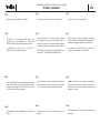
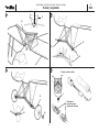
Bild 9
- Die Servos in die Zusatzrahmen 15 einsetzen und mit
einem Tropfen Sekundenkleber fixieren.
- Servos in den Rahmen 6 einsetzen. Die Rahmen noch
nicht miteinander verkleben. Die Servos müssen noch
verschiebbar bleiben.
Bild 10
- Die Schlitze für Seitenrudergestänge 16 und Höhenruder-
gestänge 17 im Rumpfheck einschneiden. Gestänge mit
Führungsröhrchen einschieben.
- Ende jeweils 90° abwinkeln und im Ruderhorn einhängen.
- Zur Sicherung ein kurzes Stück Kunststoffrohr 18 auf das
Ende schieben und mit einem Tropfen Sekundenkleber
sichern.
Bild 11
- In der gleichen Art das vordere Ende der Gestänge bear-
beiten und in den Servohebeln einhängen.
- Führungsröhrchen am Rumpfende und an Spant 4 ver-
kleben.
- Servos mit der Fernsteuerung in Neutralstellung, Ruder in
Mittelstellung bringen. Die Servos mit den Zusatzrahmen
dabei entsprechend verschieben.
- Zusatzrahmen 15 am Servorahmen 6 in dieser Position
verkleben.
Bild 12
- Die Halbschalen des Heckrads 19 aufeinanderkleben.
- Den Stützspant 20 mit dem Hecksporn 21 verkleben. Rad
auf die Achse schieben und ebenfalls mit einem
Stückchen Kunststoffrohr 18 sichern. Schlitz einschnei-
den, Einheit einkleben.
Fig. 9
- Glue the servos to the support plate 15 with a drop of
cyano.
- Fit the servos and the support plate in the servo plate 6,
but do not glue the plates together at the moment; you
may need to shift the servo position.
Fig. 10
- Cut the slots in the fuselage for the rudder pushrod 16 and
the elevator pushrod 17. Fit the pushrods and guide tubes
in the fuselage.
- Connect the formed end of the pushrods to the horns
- Push a small piece of plastic tube 18 onto the end of the
wire, and secure with a drop of cyano.
Fig. 11
- Connect the front end of the pushrod to the servo output
arm in the same way.
- Glue the guide tubes to the fuselage and former 4.
- Set the servos to neutral from the transmitter, and hold the
control surfaces in the neutral position.
- Glue the support plate 15 to the servo plate 6.
Fig. 12
- Glue parts 19 together to form the tail wheel.
- Glue the tail wheel leg 21 to the balsa support 20. Secure
the wheel with a piece of plastic tube 18. Cut a slot and
glue the skid assembly in the slot in the fuselage.
Fig.9
- Installer les servos dans les cadres supplémentaires 15 et
fixer avec une goutte de colle cyanoacrylate.
- Installer les servos dans les cadres 6. Ne pas coller les
cadre ensemble pour l’instant. Les servos doivent pouvoir
encore être déplacés.
Fig. 10
- Entailler les fentes pour la tringle de gouverne de direction
16 et de profondeur 17 dans l’arrière du fuselage. Glisser
les tringles dans des tubes-guides et les tubes en place.
- Cintrer les extrémités des tringles de 90° et les accrocher
aux guignols.
- Pour fixer, glisser un petit morceau de tube de plastique
18 sur l’extrémité et l’y fixer avec une goutte de colle
cyanoacrylate.
Fig. 11
- Traiter de la même manière l’extrémité avant des tringles
et l’accrocher au palonnier du servo correspondant.
- Coller les tubes-guides à l’extrémité du fuselage et au
couple 4.
- Amener les servos au neutre avec l’ensemble de radio-
commande. Disposer les gouvernes au neutre. Déplacer
les servos en conséquence avec le cadre supplémen-
taire.
- Coller le cadre supplémentaire 15 au cadre des servos 6
dans cette position.
Fig. 12
- Coller ensemble les demi-coquilles de la roue de queue
19.
- Coller le couple de renfort 20 à l’éperon 21. Glisser la
roue sur l’axe et l’y fixer également avec un morceau de
tube plastique 18. Couper une fente, installer l’unité et la
coller.
La page est en cours de chargement...

Bücker Jungmeister
13
Bauanleitung, Assembly instructions, Notice de montage
3041
No.
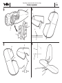
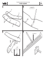
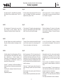
Bild 13
- Zwei Halterungen 22 nach Markierungenfür die Flächen-
streben auf die Oberseite der unteren Tragfläche 23, vier
Halterungen auf die Unterseite der oberen Tragfläche 24
kleben.
Bild 14
- Nach den Öffnungen der Halterungen rechteckige Vertie-
fungen für die Flächenstreben einschneiden. Tiefe: maxi-
mal halbe Flächendicke.
Bild 15
- Die untere Tragfläche mittig auf den Rumpf kleben. X
rechts = X links. Die Fläche muß rechtwinklig zur Rumpf-
längsachse sitzen.
-- Die schwarzen Rumpfdekorbilder einige Minuten in
Wasser legen und auf dem Rumpf aufbringen.
Bild 16
- Je zwei Flächenstreben 25 - 29 und die Hauptfahrwerks-
streben 30 - 34 aus den beigefügten Balsastreifen gemäß
der 1:1 Zeichnung auf Seite 5 zuschneiden.
- Die Schnittkanten überschleifen.
Fig. 13
- Glue the strut supports 22 to the upper face of the bottom
wing 23 and the lower face of the top wing 24 at the
marked points.
Fig. 14
- Cut rectangular slots for the struts in the wings. Maximum
slot depth: half the wing thickness.
Fig. 15
- Glue the bottom wing 23 to the fuselage 5. Note that the
wing must be positioned centrally and „square“ relative to
the fuselage centreline (X right = X left).
- Place the water-slide trim stripe transfers in water for a
few minutes, then apply them to the fuselage.
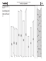
Fig. 16
- Cut to length all the wing struts 25-29 (two each) and the
undercarriage struts 30-34 from the strip balsa supplied,
as shown in the drawing on page 5 .
- Sand the cut ends at the correct angle.
Fig. 13
- Coller deux supports 22 pour les traverses de l’aile sur
l’extrados de l’aile du bas 23 et quatre supports sur l’in-
trados de l’aile du haut 24 selon les repères.
Fig. 14
- En fonction des dégagements des supports, entailler des
concavités carrées pour les traverses de l’aile.
Profondeur maximale : la moitié de l’épaisseur de l’aile.
Fig. 15
- Coller l’aile du bas au centre du fuselage. X à droite = X
à gauche. L’aile doit être perpendiculaire à l’axe longitudi-
nal du fuselage.
- Installer les autocollants noirs du fuselage quelques min-
utes dans l’eau et les appliquer au fuselage.
Fig. 16
- Couper les étais d’aile 25 - 29 (deux de chaque) et les
étais d’atterrisseur principal 30 - 34 dans les bandes de
balsa fournies selon les indications du schéma à l’échelle
1 de la page 5.
- Poncer les arêtes de coupe.
La page est en cours de chargement...

Bücker Jungmeister
15
Bauanleitung, Assembly instructions, Notice de montage
3041
No.
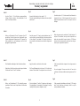
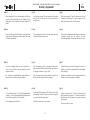
Bild 17
- Die Schablonen "S" zum Zusammenbau von Rumpf und
Tragflächen nach Zeichnung vorbereiten.
- Die Schablonen auf dem Baubrett fixieren, dabei den
Rumpf mit unterer Tragfläche und die obere Tragfläche
einsetzen. Auf mittigen Sitz achten. Teile mit Stecknadeln
fixieren. Korrekte Position der Tragflächen zueinander
prüfen. Vorsichtig arbeiten, Schaumteile sind druck-
empfindlich.
- Die äußeren Streben 25 und 26 einkleben. Sorgfältig ar-
beiten. Die Position der Flächen zueinander entscheidet
über die Flugeigenschaften. Die Flächen dürfen nicht ge-
geneinander verdreht, verschoben oder verwunden sein.
Der Einstellwinkel muß gemäß Schablonen "S" eingehal-
ten werden.
Bild 18
- Die inneren Streben 27, 28 und 29 zwischen oberer Trag-
fläche und Rumpf spannungsfrei einkleben. Auch in der
Mitte müssen die Einstellwinkel der Flächen zueinander
eingehalten werden.
Bild 19
- Vordere Fahrwerksstrebe 30 mit der Verstärkung 35 ver-
kleben und in die untere Fläche einsetzen. Hintere Strebe
31 einsetzen, Streben an der Fläche verkleben. Darauf
achten, daß die Streben zueinander fluchten.
Bild 20
- Die Hartschaum-Fahrwerksverkleidung 36 nach der Form
des Fahrwerks zuschneiden und zwischen die Streben
kleben.
Fig. 17
- Prepare the wing assembly jigs „S“ as shown in the draw-
ing.
- Fix the assembly jigs to the building board, at the same
time fitting the fuselage and bottom wing into them. Fit the
top wing and pin all the parts together. Check that the top
wing is correctly positioned relative to the bottom wing
and the fuselage. Work carefully, because the foam is
quite delicate, and easily damaged.
- Glue the outboard wing struts 25 and 26 in place, working
as carefully and accurately as possible - the correct posi-
tion of the top wing relative to the bottom wing is crucial if
the model is to fly well. The wings must not be warped,
and the angle of incidence must be correct as dictated by
the jig.
Fig. 18
- Glue the inboard wing struts 27, 28 and 29 between the
fuselage and the wing. Note that the struts must not proj-
ect above the top wing. With the help of the jig check that
the angle of incidence of both wings is correct at the cen-
tre section.
Fig. 19
- Glue the front undercarriage legs 30 to the triangular rein-
forcements 35, and insert them in the fuselage. Add the
rear undercarriage legs 31 and glue them to the wing.
Check that the undercarriage legs line up correctly with
each other.
Fig. 20
- Trim the triangular foam fairings 36 to the shape of the
undercarriage legs and glue them in place.
Fig. 17
- Préparer les gabarits „S“ d’assemblage du fuselage et
des ailes selon les indications du schéma.
- Fixer les gabarits sur le chantier et installer le fuselage
avec l’aile du bas et avec l’aile du haut. Veiller à ce
qu’elles soient centrées. Fixer les éléments avec des
aiguilles de fixation. Contrôler la correction de la position
des ailes l’une par rapport à l’autre. Travailler avec beau-
coup de soin, les éléments de mousse sont très sensibles
à la pression.
- Coller les étais extérieurs 25 et 26. Travailler avec beau-
coup de soin. La position mutuelle des ailes détermine le
comportement en vol ultérieur. Elle ne doivent pas être
gauchie l’une par rapport à l’autre, ni décalées, ni de tra-
vers. L’angle d’attaque doit être préservé selon les indica-
tions des gabarits „S“.
Fig. 18
- Coller les étais intérieurs 27, 28 et 29 entre l’aile du haut
et le fuselage. Au centre également, l’angle d’incidence
des ailes doit être préservé mutuellement.
Fig. 19
- Coller l’étai d’atterrisseur avant 30 au renfort 35 et mettre
l’aile du bas en place. Mettre l’étai arrière 31 en place,
coller les étais à l’aile en veillant à ce qu’ils soient par-
faitement en ligne les uns par rapport aux autres.
Fig. 20
- Couper le carénage d’atterrisseur 36 en mousse dure à la
forme de l’atterrisseur et le coller entre les étais.

Bücker Jungmeister
16
Bauanleitung, Assembly instructions, Notice de montage
3041
No.
21 22
23 24
32
33
34
33
32
37
38
38
40
40
39
Stecksystem
connector system
Système de connexion
X links X rechts
Schema, scheme, schéma
F

Bücker Jungmeister
17
Bauanleitung, Assembly instructions, Notice de montage
3041
No.
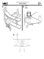
Bild 21
- Die übrigen Streben 32 - 34 gemäß Zeichnung einkleben.
Auf korrekten Sitz des Fahrwerks achten. X rechts = X
links.
Bild 22
- Die Fahrwerksachse 37 einsetzen und nur an den mit-
tleren Streben mit Epoxy verkleben. Außen die
Gummiringe 38 aufziehen, damit das Fahrwerk federt.
Bild 23
- Die Räder 39 werden innen und außen mit den Nietchen
40 gesichert. Nietchen verkleben. Gummiringe nicht mit-
verkleben.
Bild 24
- Den Motor entstören. Dazu die Kondensatoren 47 nF jew-
eils mit einem Beinchen an das Gehäuse löten, welches
dazu blankzufeilen ist. Zweites Beinchen mit
Isolierschlauch an die Motorpole stecken. Die Beinchen
des Kondensators mit Isolierschlauch versehen und
ebenfalls an die Motorpole stecken.
- Ferritkern "F" aufschieben. Das Motoranschlußkabel an
die Motorpole löten, die Kondensatoren werden dabei mit-
verlötet.
- Das Stecksystem anbringen. Position der Stecker zuein-
ander beachten.
- Regleranleitung beachten.
Fig. 21
- Glue the remaining undercarriage struts 32-34 in place as
shown in the drawing. Check that the undercarriage is
aligned correctly (X right = X left).
Fig. 22
- Fit the wheel axle 37 through the undercarriage legs and
epoxy it to the undercarriage leg joiner. Wrap the rubber
bands 38 round the axles to provide springing.
Fig. 23
- The wheels 39 are secured inside and out with the plastic
rivets 40 which are glued to the undercarriage axle 37.
Take care not to get glue on the rubber bands.
Fig. 24
- Attach the suppressors 47 nF to the electric motor as fol-
lows: solder one pin of each capacitor to the motor can,
after filing the metal surface perfectly clean. Fit an insu-
lating sleeve on each of the second pins and push them
through the motor terminals. Fit insulating sleeves on both
pins of the capacitor and fit the pins through the motor ter-
minals the same way.
- Fit fhe ring "F". Solder the power cables to the motor ter-
minals, soldering the capacitor pins in place at the same
time.
- Attach the plugs of the connector system. Check the posi-
tion of the plugs.
- Read the instructions supplied with the speed controller.
Fig. 21
- Coller les autres étais 32 - 34 selon les indications du
schéma. Veiller à la correction de la position de l’atterris-
seur. X à droite = X à gauche.
Fig. 22
- Mettre l’axe d’atterrisseur 37 en place et le coller unique-
ment aux étais centraux avec de la colle époxy. À l’ex-
térieur, installer les élastiques 38 assurant l’amortisse-
ment de l’atterrisseur.
Fig. 23
- Les roues 39 seront fixées à l’intérieur et à l’extérieur
avec les petits rivets de plastique 40. Coller les rivets. Ne
pas coller les élastiques.
Fig. 24
- Antiparasiter le moteur. Pour ce faire, souder chaque fois
une broche des condensateurs au carter du moteur,
préalablement limé. La seconde broche sera connectée
aux pôles du moteurs avec des morceaux de gaine
isolante.
- Munir les broches du condensateur de morceaux de
gaine isolante et les planter également sur les pôles du
moteur.
- Munir le cordon de la bague "F". Souder le cordon de con-
nexion du moteur aux pôles du moteur en soudant simul-
tanément les broches des condensateurs.
- Installer le système de connexion sur le variateur, le
moteur et l’accu. Tenir compte de la position mutuelle des
connecteurs.
- Tenir compte des indications de la notice du variateur.
La page est en cours de chargement...

Bücker Jungmeister
Bauanleitung, Assembly instructions, Notice de montage
3041
No.
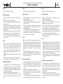
Bild 25
- Motorwelle mit Schleifpapier in Längsrichtung aufrauhen.
- Etwas Loctite in die Bohrung des Ritzels träufeln. Das Ritzel
auf die Motorwelle aufpressen.
- Die Unterlegscheibe auflegen und das Getriebegehäuse auf
den Motor stecken.
- Innenzahnrad gut einfetten.
- Die Darstellung zeigt den Antrieb mit montierter Luftschrau-
be.
Bild 26
- Antrieb einschieben, ø 1,5 mm Löcher bohren. Antrieb befe-
stigen. Luftschraube auf 8 mm zentrisch aufbohren, auf die
Welle schieben und mit der M 8 Mutter sichern.
Bild 27
- Den Regler mit Doppelklebeband an der Akkubox befesti-
gen.
- Regler und Servos am Empfänger anschließen.
- Den Empfänger mit Doppelklebeband an der Empfänger-
platte 7 befestigen.
Bild 28
- Empfangsanlage betriebsbereit zusammenstecken.
- Laufrichtung der Ruder und Ruderausschläge prüfen.
- Motorlauf prüfen.
- Der Motor muß von vorn gesehen gegen den Uhrzeiger-
sinn drehen. Ist dies nicht der Fall, die Kabel an den
Motorpolen durch Umlöten vertauschen.
- Bei allen Montage-, Wartungs- und Einstellarbeiten nie-
mals in den Drehkreis der Luftschraube geraten - Verlet-
zungsgefahr.
Fig. 25
- Roughen the motor shaft with abrasive paper horizontally.
Apply a drop of Loctite to the hole in the pinion. Press the
pinion onto the motor shaft
- Install the washer and fit the gearbox on the motor.
- Grease the internal gear generously.
- The drawing shows the motor assembly with the propeller
fitted.
Fig. 26
- Install the power unit in the fuselage and secure it after
drilling the 1.5 mm holes. Drill out the propeller hub using an
8 mm Ø drill, slip it on the shaft and secure it with an M8 nut.
Fig. 27
- Attach the speed controller to the battery box using double-
sided foam tape.
- Connect the speed controller and the servos to the receiver.
- Fix the receiver to the receiver plate 7 inside the cockpit
using double-sided foam tape.
Fig. 28
- Connect all the components of the receiving system.
- Check the direction and travel of the rudder and elevator
control systems.
- Check the motor control system.
- Check the direction of rotation of the motor as follows:
when viewed from the front the propeller should rotate
anti-clockwise. If it rotates in the opposite direction,
un-solder the cables at the motor terminals and swap
them over.
- Caution: when the battery is connected to the power
system it is essential to keep well clear of the rotational
plane of the propeller when working on the model, as
the spinning blades can easily injure you if the motor
unexpectedly starts running.
19
Fig. 25
- Poncer l'arbre du moteur avec du papier de verre en
direction horizontal.
- Disposer une goutte de Loctite dans le trou du pignon.
Planter le pignon sur l’arbre du moteur.
- Installer la rondelle comme intercalaire et planter le carter
du mécanisme sur le moteur.
- Bien graisser la roue dentée intérieure.
- L'illustration présente l'entraînement avec l'hélice en place.
Fig. 26
- Mettre l’entraînement en place, percer les truos de 1,5 mm
et le fixer. Porter le trou de l’hélice à 8 mm en observant la
concentricité au perçage, la glisser sur l’arbre et l’y fixer
avec l’écrou M 8.
Fig. 27
- Fixer la variateur avec de l’adhésif double face au logement
de l’accu.
- Raccorder le variateur et les servos au récepteur.
- Fixer le récepteur avec du double face à la platine du
récepteur 7.
Fig. 28
- Mettre l’ensemble de réception en ordre de marche en
l’interconnectant.
- Contrôle la direction du débattement des gouvernes et leur
course
- Contrôler le sens de rotation du moteur.
- Le moteur, vu de face, doit tourner dans le sens
contraire des aiguilles d’une montre. Si ce n’est pas le
cas, intervertir les fils sur les pôles du moteur en les
dessoudant puis en les ressoudant.
- Pour tous les travaux de montage, d’entretien et de
réglage ne jamais approcher la main du plan de rotation
de l’hélice, danger de blessure.
La page est en cours de chargement...

Bücker Jungmeister
21
Bauanleitung, Assembly instructions, Notice de montage
3041
No.
Bild 29
- Restliche Dekorbilder aufbringen.
Bild 30, Auswiegen
- Den Schwerpunkt „C.G.“ beidseitig am Rumpf anzeich-
nen.
- Das Modell komplett zusammenbauen.
- Den Akku einschieben und mit Schaumgummi gegen Ver-
rutschen sichern.
- Das Modell im Schwerpunkt unterstützen und aus-
pendeln lassen. Die Idealstellung ist erreicht, wenn das
Modell mit leicht nach unten hängendem Vorderteil in der
Waage bleibt.
- Hängt das Leitwerk nach unten, muß vorn Trimmblei zu-
gegeben werden. Wenn das Rumpfvorderteil zu stark
nach unten hängt, hinten mit Trimmblei korrigieren.
- Trimmblei, welches in das Styropor eingedrückt wird, mit
Epoxy sichern.
Bild 31
- Tip: Um eine bessere Wendigkeit beim Kurvenflug zu
erreichen, kann die V-Form erhöht werden. Dazu gemäß
Skizze eine geradlinige Verspannung aus
dünnemTakelgarn oder einem Nylonfaden zwischen den
unteren und oberen Flächenstreben herstellen. V-Form
über die Spannung regulieren. (Anhaltswert 2 cm pro
Seite).
- Auf gleichmäßige Einstellung der V-Form rechts und links
achten.
- Geeignete V-Form erfliegen, dann die Verspannung mit
Foam Speed oder ropoxi an den Streben fixieren.
Einfliegen, Flughinweise
- Für den Erstflug einen nicht zu windigen Tag aussuchen.
Als Gelände eignet sich eine flache, freie Wiese am
besten. Nähe von Hochspannungsleitungen, verkehrsre-
ichen Straßen, Ansiedlungen und Flugplätzen sowie an-
deren Hindernissen meiden.
- Nochmals eine Funktionskontrolle durchführen.
- Immer den Gasknüppel in Stellung „Motor aus“ bringen,
den Sender einschalten. Erst dann den Akku anschlie-
ßen.
Fig. 29
- Apply the remaining water-slide transfers.
Fig. 30, Balancing
- Mark the balance point (Centre of Gravity - CG) on both
sides of the fuselage.
- Assemble the model completely.
- Install the flight battery and pack foam rubber against it to
prevent it shifting.
- Support the model at the marked points and allow it to
hang freely. Ideally it will now balance level, with the nose
inclined slightly down.
- If the tail hangs down, add lead ballast at the nose. If the
nose hangs down too far, add lead ballast at the tail.
- Any lead ballast can simply be pushed into the styrofoam
and secured with a smear of epoxy.
Fig. 31
- Tip: to improve the model’s manoeuvrability and turning
radius, you can increase the dihedral slightly. This is done
by cutting a length of thin thread or nylon line and tension-
ing it between the bottom and the top wing struts as shown
in the sketch. The amount of tension in the thread dictates
the dihedral; we recommend 2 cm per side as starting
point.
- Check that the dihedral is the same on both sides.
- Try different dihedral settings until you are satisfied, then
apply a drop of Foam Speed or ropoxi to fix the thread to
the structure permanently.
Test flying, flying notes
- For the first flight wait for a day with no more than a light
breeze. The ideal flying site is a large, flat, open grassy
meadow. Keep well clear of high-tension overhead
cables, busy roads, residential areas and airfields, and all
obstacles.
- Check all the working systems one more time.
- Always move the throttle stick to the „motor off“ position
before you switch the transmitter on, and only then con-
nect the flight battery.
- When switching off always disconnect the battery from the
speed controller first (to switch off the receiving system),
Fig. 29
- Appliquer les autocollants de décoration.
Fig. 30, Équilibrage
- Marquer l’emplacement du centre de gravité („C.G.“) de
chaque côté sur le fuselage.
- Assembler complètement le modèle.
- Mettre l’accu en place et le bloquer avec de la mousse
plastique afin qu’il ne puisse glisser.
- Caler le modèle au niveau de son centre de gravité et le
laisser en suspens. Il atteint sa position idéale lorsque il
reste en équilibre avec le nez légèrement piqueur.
- Si les empennages pendent vers le bas, il faut ajouter du
plomb de lestage à l’avant. Si le nez est trop piqueur, cor-
riger en ajoutant du plomb de lestage à l’arrière.
- Enfoncer le plomb de lestage dans le styropor et l’y fixer
avec de la colle époxy.
Fig. 31
- Un conseil: pour obtenir une meilleure maniabilité en
virage, il est possible d’accroître le dièdre. Pour ce faire,
selon les indications du schéma, réaliser un haubanage
rectiligne en fil fin ou à l’aide d’un fil de nylon entre les
étais d’aile inférieur et supérieur. Assurer la régulation du
dièdre à l’aide de la tension du haubanage. (Valeur de
référence : 2 cm par côté). Veiller à ce que le réglage du
dièdre soit identique à droite et à gauche.
- Faire des essais en vol avec le dièdre approprié et fixer
ensuite le haubanage aux étais avec du Foam Speed ou
du ropoxi.
Le premier vol, conseils de pilotage
- Pour le premier vol nous vous recommandons de choisir un
jour à vent faible. Le terrain de vol peut être une prairie
plane et dégagée relativement vaste. Éviter la proximité
des lignes à haute tension, des routes fréquentées, des
lotissements et des terrains d’aviation de même que toute
forme d’obstacle.
- Effectuer un nouveau contrôle des fonctions.
- Amener toujours le manche des gaz en position „moteur
coupé“. Mettre l’émetteur en marche puis raccorder seule-
ment l’accu.

Bücker Jungmeister
22
Bauanleitung, Assembly instructions, Notice de montage
3041
No.
- Zum Ausschalten immer die Verbindung Akku - Motorregler
trennen, erst dann Empfangsanlage und den Sender aus-
schalten.
- Für den Handstart sollte ein Helfer anwesend sein, der das
Modell in die Luft befördern kann.
- Das Modell mit laufendem Motor mit nicht zu geringem
Schub gerade und horizontal aus der Hand starten. Sofort
die Steuerung übernehmen.
- Nach dem Start den Steigflug nicht zu früh einleiten, son-
dern das Modell in flachem Horizontalflug Fahrt aufnehmen
lassen.
- Überzogene Flugzustände vermeiden. In diesem Fall
nachdrücken und in den Horizontalflug übergehen.
- Falls erforderlich, die entsprechenden Ruder nachtrimmen.
- Das Flugverhalten genau beobachten. Sind Korrekturen
erforderlich, so sind diese nach der ersten Landung vorzu-
nehmen.
- Das Modell kann auch vom Boden gestartet werden. Es
eignet sich eine Hartbelagspiste.
- Vor dem ersten Bodenstart einige Rollversuche durchfüh-
ren, um sich mit dem Verhalten des Modells am Boden ver-
traut zu machen.
- Sind Ihnen die Reaktionen des Modells bekannt, wird das
Modell mit der Nase genau gegen den Wind gestellt. Kon-
tinuierlich bis zur vollen Motorleistung Gas geben und das
Modell durch leichtes Ziehen des Höhenruders vom Boden
abheben. Das Modell nicht überziehen. Falls erforderlich,
sofort nachtrimmen.
Reparaturen
- Bei einer eventeuell erforderlichen Reparatur an Styropor-
teilen wie folgt vorgehen:
- Bruchstelle freilegen. Die Bruchstelle ansonsten so wenig
wie möglich verändern.
- Die Teile unter Zugabe von Epoxy wieder paßgenau zu-
sammenfügen und ausrichten.
- Die Klebestelle gut aushärten lassen. Durch Klebstoff ent-
standene Unregelmäßigkeiten beschleifen.
- Bei fehlenden Bruchstücken diese durch gleichwertiges
Styropormaterial ersetzen.
robbe Modellsport GmbH & Co. KG
Technische Änderungen vorbehalten
and only then switch off the transmitter.
- If you are going to hand-launch the model we recommend
that you ask somebody to launch for you, so that you can
concentrate on controlling the model right from the outset.
- Switch the motor on, and launch the model with a fairly
hard push directly into any wind, keeping the wings and
fuselage level. Take control of the model immediately.
- Don’t allow the model to climb steeply initially; it is much
safer to allow speed to build up in level flight at first.
- It is essential to avoid the model stalling (nose high, too
slow). Apply down-elevator to prevent this happening and
return the model to level flight.
- If necessary adjust the transmitter trims until the model
flies „hands off“.
- Watch the model’s behaviour in the air very carefully. If
you have to move the trims, adjust the mechanical link-
ages when the model is back on the ground so that you
can return the trims to centre.
- The model can also be taken off from the ground if you
have access to a hard, smooth take-off strip.
- Carry out a few taxi-ing tests before you try a take-off, so
that you get a „feel“ for the model’s general ground-han-
dling, and are familiar with the model’s response to the
rudder.
- When you feel confident about the model’s characteristics
place it on the ground with the nose facing directly into
wind. Steadily advance the throttle until the stick is at „full
throttle“. Allow the model to pick up plenty of speed before
applying gentle up-elevator to lift off. Take care not to slow
the model down too much and cause a stall. Adjust the
trims immediately if necessary.
Repairs
- If you should ever need to repair the styrofoam parts, this
is the procedure:
- Expose the break completely. Otherwise do not modify
the broken surfaces at all.
- Apply a thin coating of epoxy to the break, push the parts
back together and align them carefully.
- Allow the glue to harden thoroughly. Remove any irregu-
larities caused by the adhesive.
- If a section of the broken component is missing, cut a
replacement part from the same grade of styrofoam.
We reserve the right to alter technical specifications.
- Pour couper, procéder dans l’ordre inverse en coupant
d’abord la liaison de l’accu pour couper l’ensemble de
réception avant d’arrêt l’émetteur.
- Pour le lancement à la main, il est recommandé de deman-
der l’assistance d’un tiers qui soit en mesure de lancer le
modèle.
- Lancer le modèle avec une bonne poussée, droit et hori-
zontal, alors que le moteur tourne. Prendre immédiatement
les commandes.
- Après le lancement, ne pas engager le vol ascensionnel
trop tôt mais permettre au modèle de prendre de la vitesse
avec un vol rectiligne relativement horizontal.
- Éviter de cabrer le modèle. Si c’est le cas, pousser le
manche de profondeur afin qu’il retrouve son assiette de
vol.
- Si nécessaire, trimmer la gouverne qui l’exige.
- Observer le comportement en vol du modèle. Si des cor-
rections s’impose, les appliquer après avoir atterri.
- Il est également possible de faire décoller le modèle du sol.
Il faut une piste en dure.
- Avant d’effectuer le premier décollage du sol, effectuer
plusieurs séances de roulage au sol pour se familiariser
avec le comportement du modèle.
- Lorsque les réactions du modèle sont reconnues, l’installer
le nez exactement dans le vent et donner des gaz en con-
tinu jusqu’au plein régime et dégager le modèle du sol en
tirant légèrement sur le manche de profondeur. Ne pas trop
tirer, si nécessaire, rectifier immédiatement au niveau des
trims.
Réparations
- Si une réparation quelconque s’impose au niveau des élé-
ments de styropor, procéder comme suit:
- Dégager les emplacement à réparer. Sinon, modifier le
moins possible le secteur abîmé.
- Réunir les deux parties de la cassure, en les ajustant avec
précision, après les avoir enduites de colle époxy.
- Bien laisser sécher la colle avant de poncer les emplace-
ments présentant des irrégularités à cause de la colle.
- Si des morceaux manquent au niveau d’une cassure, les
remplacer par une matière identique.
Sous réserve de modification technique
La page est en cours de chargement...
-
 1
1
-
 2
2
-
 3
3
-
 4
4
-
 5
5
-
 6
6
-
 7
7
-
 8
8
-
 9
9
-
 10
10
-
 11
11
-
 12
12
-
 13
13
-
 14
14
-
 15
15
-
 16
16
-
 17
17
-
 18
18
-
 19
19
-
 20
20
-
 21
21
-
 22
22


ROBBE Bucker Jungmeister 3041 Assembly And Operating Instructions Manual
- Catégorie
- Jouets télécommandés
- Taper
- Assembly And Operating Instructions Manual
dans d''autres langues
- English: ROBBE Bucker Jungmeister 3041
- Deutsch: ROBBE Bucker Jungmeister 3041
Documents connexes
-
ROBBE Easy Go 3043 Assembly And Operating Instructions Manual
-
-
-
-
-
-
-
ROBBE Arcus Assembly And Operating Instructions Manual
-
-