ROBBE BK 117 Assembly And Operating Instructions Manual
- Catégorie
- Jouets
- Taper
- Assembly And Operating Instructions Manual

Montage- und Bedienungsanleitung
Assembly and operating instructions
Notice de montage et d’utilisation
BK 117
No. S 2918

BK 117
No.
S 2918
Der Rumpfbausatz BK 117 ist für den Einbau von FUTURA-Mechaniken in Verbindung mit dem Umbausatz 1:10 [S2931] sowie Benzinmotor ZG 23 vorgesehen.
Als Zubehör für den ZG 23 werden der Schalldämpfer [S0906] und die Auspuffverlängerung BK 117 [S2946] benötigt.
Die Teile in [ ] Klammern sind nicht im Rumpfbausatz enthalten.
Bei Umbau des Heckgetriebes [S2919] (für Antriebsdraht Ø 2 mm) auf den Heckrotor Ø 24 mm [S2977] werden benötigt:
- Heckgetriebegehäuse R+L [S4624]
- Distanzhülse [S4833]
- Kupplung hinten [S4747]
Für den Zweiblattrotorkopf werden schwerpunktkorrigierte GfK-Hauptrotorblätter [S2939 rechtsdrehend] oder [S2940 linksdrehend] empfohlen.
Der Vierblattrotorkopf [S2914] sollte nur mit entsprechend schwerpunktkorrigierten GfK-Rotorblättern geflogen werden. Zusätzlich werden bei seiner Verwendung
der Taumelscheibenmitnehmer [S2802], ein Kugelbolzen M2,5 x 6 [S4442], 4 Gestänge M2,5 x 60 [S3589] und 8 Kugelgelenke 2,5 [S3083] benötigt.
Lange Heckrotorblätter (Holz 140 mm lang) sind unter der Best.-Nr. S3855 erhältlich.
Als Klebstoffe empfehlen wir: UHU-plus endfest 300 und robbe ropoxi, [5066].
Rumpfausbau
Rumpföffnungen (a-j), gemäß den Anrissen, herstellen. Dies geschieht durch Aussägen, Ausfeilen oder mit Hilfe eines kleinen Elektrofräsers.
Die Verglasungen (b, c, e, f) werden, wie in Ansicht A (am Beispiel einer Türscheibe) gezeigt, mit ca. 6 mm breitem Rand ausgeschnitten und in den Rumpf
eingepaßt. Öffnungen evtl. etwas nacharbeiten. Frontscheibe (d) in den Absatz einpassen. Beide Rumpföffnungen (a) sollten, zur besseren Luftzufuhr und zum
Anlassen des Motors, unverschlossen bleiben.
Beachten: Die Scheiben (b, c, e, f) werden später, nach dem Lackieren, von innen in die Rumpföffnungen eingesetzt und am Rand verklebt (Pattex transparent).
Bei einem Cockpitausbau nach eigenem Ermessen, kann die Frontscheibe auch mit Blechschrauben 2,2x6,5 (S0042) befestigt werden.
Der Spantensatz ist bereits zugeschnitten. Er sollte probeweise zusammengesetzt und nach evtl. Nacharbeit, wie in Ansicht B und C gezeigt, ausgerichtet und
sorgfältig verleimt werden (Weißleim oder dicker Sekundenkleber). Die beiden seitlichen Auflagen (19) werden jedoch erst nach dem Einsetzen in den Rumpf und
dem endgültigen Verkleben des Spantenaufbaues eingesetzt und verklebt. Mechanik aufsetzen und an den hinteren Befestigungsbohrungen anschrauben
(Ansicht C, Detail k). Vorderen Befestigungspunkt (l) übertragen, Mechanik abnehmen und 4 mm Bohrung herstellen.
Ansicht C: Kufenbügelhalterungen (S3352) mit Klebstoff (Epoxydharz) von innen in die vorgesehenen Ausschnitte einsetzen. Einschlagmuttern M3 (S2466), von
außen in den vorderen und hinteren Spant eindrücken, mit Schraube fest ins Holz ziehen und zusätzlich mit Epoxydharzklebstoff sichern.
Ansicht K: Trägerplatte (S1682) auf der Rückseite sowie Klebefläche des Rumpfes aufrauhen. Zentrierungsbohrungen im Rumpf evtl. nacharbeiten, und die
Trägerplatte mit UHU-plus endfest 300 verkleben.
Folgende Mechanikteile durch beiliegende Teile ersetzen:
- Hauptrotorwelle 186 mm durch Hauptrotorwelle 196 mm (S4775)
- Taumelscheiben-Gestänge [S3203 + S0497] durch (S0436 + S0528)
- Falls erforderlich, Heckwellenanschluß [S3300] (für Antriebsdraht Ø 2 mm) durch Kupplung vorn (S4742)
- Falls erforderlich, Heckrotorwelle [S3380] (für Antriebsdraht Ø 2 mm) durch Heckrotoreingangswelle (S3705)
Bei den Trainer- Mechaniken die Heckrohrverlagerung [S4325] / [S4606] durch das Distanzstück [S4136] ersetzen.
Ansicht L: Die Haltewinkel (S1425) an den hinteren Befestigungsbohrungen des Distanzstückes (S4136 oder S4191) mit Inbusschrauben M3x45 (S1722) und
Stopmuttern M3 [S0012] befestigen. Mechanikhalter (S4047) in das Distanzstück eindrücken.
Zeichnung D: Das Heckgetriebe [S2919] (für Antriebsdraht ø 2mm) unter Verwendung der Getriebeschalen [S4624], der Distanzhülse [S4833], den PT-
Schrauben [S4283, S1005] und der Heckeingangswelle [S4747] auf das Heckgetriebe ø24mm [S2977] umrüsten.
Den vorbereiteten Spantenaufbau durch die obere Öffnung in den Rumpf einschwenken. Mechanik einsetzen und mit dem Spantenaufbau verschrauben
(Inbusschrauben M4x25 + M3x25).
Einheit mittig ausrichten. Spantenaufbau am Rumpf anheften und anschließend sorgfältig mit Epoxydharzklebstoff verkleben.
Obere Mechanikbefestigung, gemäß Ansicht L herstellen. Je nach Spanteneinbau kann der Abstand der Mechanik zur Rumpfwand unterschiedlich sein. Länge
der Halterung (7) in Verbindung mit dem Halter (20) und der Sperrholzunterlage anpassen, zweites Befestigungsloch bohren. Sperrholz an der entsprechenden
Stelle des Rumpfes einkleben. Befestigungsbohrungen 2 mm für den Halter (20) herstellen und Halter anschrauben.
Ansichten F + G: Kufenbügel (S1738) in den Rumpf einschieben, mittig ausrichten und mit Kufenbügelhalterungen (S3352) sowie Inbusschrauben M3x25
(S0037) am Spantenaufbau anschrauben. Die Kufenbefestigung (S1737) auf die Kufenrohre aufstecken. Je eine Stopmutter M3 (S0012) in die Kufenverbinder
(8) drücken (Kunststoffeinsatz der Mutter nach außen). Zur Montage der Kufenbefestigung einen Streifen Sperrholz 11x2x500 mm in die Nut der Kufenverbinder
drücken, und mit dessen Hilfe den Kufenverbinder in das Rohr schieben, bis das Gewinde in der Bohrung der Kufenbefestigung sichtbar wird. Inbusschraube
M3x16 (S0031) eindrehen.
Ansichten G + H: Befestigungsschelle (9) auf die Kufenbügel (S1738) schieben. Kufenbefestigungen (S1737) auf die Kufenbügel (S1738) drücken und von hin-
ten mit Blechschraube 2,2 x 6,5 (S0042) sichern (1,5 mm vorbohren).
Verbindungswinkel (10) mit Inbusschraube M3x25 (S0037) und Stopmutter M3 (S0012) an der Befestigungsschelle und mit Senkschraube M3x10 (11) und
Stopmutter M3 (S0012) am Trittbrett befestigen, ausrichten und festziehen (Anschraubhöhe beachten).
Ansicht K: Rohr ø 20 mm (S1684) durch eine Rumpföffnung (g) in den Rumpf einführen und bis auf Anschlag in den Mechanikhalter (S4047) einschieben.
Am Rohr (S1684) eine Markierung im Abstand von 2 mm zur Halbschelle der Trägerplatte (S1682) anbringen.
Ansicht M: Rohr (S1684) aus dem Rumpf herausnehmen, an der Markierung absägen und planfeilen bzw. schleifen. Dazu die Bohrlehre (S2963) als Spannhilfe
verwenden.
Ansicht L: Mechanikhalter (S4047) aus der Mechanik ausbauen und mit dem Rohr ø 20 mm (S1684) verkleben. Klebung zusätzlich mit PT-Schraube 2,5 x 6,5
(S1005) sichern - 1,5 mm vorbohren.
Antriebsrohr ø 6 mm (S1685) so in die Bohrlehre schieben, daß es mit einem Ende bündig abschließt. An diesem Ende vom Antriebsrohr die 2 mm Löcher A und
B gemäß der Bohrlehre bohren. Das Antriebsrohr in der Bohrlehre umsetzen. Das äußere Loch mit einer Feile zum Schlitz öffnen und sauber entgraten - C.
Eine Kupplungsklaue (S4633) aufstecken und mit Schraube M2x10 (S0020) sichern. Beim Eindrehen verschiedene Lochdurchmesser der Kupplungsklaue
beachten.
2
BK 117
No.
S 2918
Ansicht K: Antriebsrohr in den Rumpf einführen und Kupplungsklaue (S4633) bis auf Anschlag in Kupplung vorn (S4742) eindrücken.
Das Antriebsrohr (S1685) 5 mm vor der Trägerplatte (S1682) mit einer Markierung „MK“ versehen.
Antriebsrohr aus dem Rumpf herausnehmen, an der Markierung absägen und planfeilen bzw. schleifen.
Dazu die Bohrlehre (S2963) als Spannhilfe verwenden. Die Kupplungsklaue vom Rohr entfernen.
Die Löcher ø 2 mm Aund B bohren. Äußeres Loch zum Schlitz öffnen - C.
Ansicht N: Antriebsrohr (S1685) ausmessen und die Positionen für die Lagerbockhülsen (S4750), mit jeweils dem selben Abstand, markieren.
Die Lagerbockhülsen (S4750) jeweils mit dem Bund zueinander mit etwas Epoxy-Kleber auf dem Antriebsrohr (S1685) festkleben. Die O-Ringe (S3544)
auf die Lagerböcke (S47482) nach Zeichnung aufschieben. Die montierten Lagerböcke (S47482) ebenfalls mit etwas Epoxy-Kleber auf den
Lagerbockhülsen (S4750) festkleben. Achtung: Es darf kein Kleber in die Kugellager (S01311) gelangen. Die Kupplungsklauen (S4633) auf das
Antriebsrohr (S1685) mit Loctite aufstecken und mit Zylinderschrauben M 2 x 10 (S0020) sichern.
Ansichten P + Q: Das 45° Getriebe montieren. Umlenkhebel bearbeiten. Getriebe mit Inbusschrauben, U-Scheiben, Bolzen und Hebel an der
Trägerplatte befestigen.
Antriebsrohr ø 6 mm (70-1686) so in die Bohrlehre schieben, daß es mit einem Ende bündig abschließt. An diesem Ende die 2 mm Löcher A und B
gemäß der Bohrlehre bohren. Das Antriebsrohr in der Bohrlehre umsetzen. Das äußere Loch mit einer Feile zum Schlitz öffnen und sauber entgraten
- C.
Eine Kupplungsklaue (S4633) mit Loctite aufstecken und mit Schraube M 2 x 10 (S0020) sichern. Beim Eindrehen verschiedene Lochdurchmesser der
Kupplungsklaue beachten.
Antriebsrohr in das Seitenleitwerk des Rumpfes einführen und Kupplungsklaue im 45° Getriebe einkuppeln.
Ansicht Q: Heckrotorspant (S4046) mit einem Abstand von 44 mm zur Seitenleitwerksvorderkante in den Rumpf einkleben.
Ansicht R: Den Heckrotorspant zusätzlich mit den Blechschrauben 2,2 x 6,5 (S0042) und den U-Scheiben (S0000) sichern.
Auf das freie Ende des Antriebsrohres (70-1686) die zweite Kupplungsklaue aufstecken. Das Heckgetriebe einkuppeln. Maß „Y“ vom Heckrotorspant
bis zur Auflage vom Heckgetriebe messen.
Ansicht M1: Beim Kürzen beachten.
- Heckrotor ø 24 mm [S2977]: Antriebsrohr mit Hilfe der Bohrlehre um Maß „Y“ + 1 mm kürzen.
Die Löcher ø 2 mm Aund B bohren. Äußeres Loch zum Schlitz öffnen - C.
Zweite Kupplungsklaue mit Loctite aufstecken und mit Schraube M 2 x 10 (S0020) sichern.
45° Getriebe aus dem Rumpf ausbauen.
Ansicht A: Höhenleitwerk (12) mittig in Ausschnitt H einkleben. Seitenleitwerk (13) ansetzen und ebenfalls verkleben.
Rumpfdeckel (16) in obere Rumpföffnung einpassen und mit dem Rumpf verbohren (1,5 mm). Getriebeabdeckung (17) nach Anriß ausschneiden, mit-
tig fixieren und ebenfalls mit dem Rumpf verbohren. Sperrholzstreifen, zur Verstärkung des Rumpfdeckels, unter die Rumpfkante kleben und ebenfalls
durchbohren. Bohrungen in Rumpfdeckel und Getriebeabdeckung auf 2 mm aufbohren.
Rumpfdeckel (16) und die Getriebeabdeckung (17) nach der Endmontage der Mechanik mit Blechschrauben 2,2x6,5 (S0042) sowie U-Scheiben
(S0000) am Rumpf befestigen.
Bohrungen zur Befestigung der Türgriffe, Antennen, Scheibenwischer und Haltegriffe an den gezeigten Stellen anbringen. Je nach Farbgebung des
Modells sind die Beschlagteile, Lüftungsgitter und Austritte vor oder nach der Lackierung zu verkleben.
Ansicht S: Seitliche Auflage (19) und Rumpfunterseite mit Öffnung für Auspuffverlängerung versehen. Auflage auf den Spantenaufbau kleben.
Nahtstellen evtl. leicht verschleifen. Holzteile mehrmals grundieren und schleifen. Durch Anstrich gegen Kraftstoff schützen. Rumpf lackieren. Nur
Kunstharzlacke verwenden.
Wichtig: Nicht unnötig viel Lack auftragen. Zuviel Lack erhöht erheblich das Gesamtgewicht. Mehrere 100 Gramm sind schnell auflackiert!
Mechanikeinbau
Die Kupplungsklauen (S4633) leicht einfetten und kompletten Starrantrieb mit Hilfsrohr unter Verwendung von Öl in das Heckrohr (S1684) einschieben.
Das Rohr ø 20 mm (S1684) mit den Servohaltern (S0940) mit Servo, den Gestängeführungen (S1241), dem zweiteiligen Gestänge (S0375, S3477) mit
Gestängeverbinder (S1242) und Gabelanschlüssen (S0059) bestücken.
Ansicht L: Einheit in den Rumpf einführen. Mechanikhalter (S4047) in das Distanzstück der Mechanik eindrücken und zusammen mit der oberen Me-
chanikbefestigung am Haltewinkel (5) festschrauben.
Ansichten P + Q: Heckservo mit Empfänger bzw. Autopilot verbinden.
Das hintere Ende des Rohres ø 20 mm (S1684) mit der Schelle (S4371) und den Inbusschrauben M 3 x 14 (S3198) an der Trägerplatte (S1682) befes-
tigen.
45° Winkelgetriebe einbauen. Dabei die Kupplungsklauen des Antriebsrohres (S1685) in der Mechanik und im 45° Winkelgetriebe einrasten lassen.
Gabelanschluß am Winkelgetriebehebel einhängen.
Kupplungsklauen des Antriebsrohres (S1686) leicht einfetten und zusammen mit dem Heckgetriebe in das Seitenleitwerk einsetzen. Dabei die
Kupplungsklauen im 45° Winkelgetriebe und Heckgetriebe einrasten lassen.
Heckgetriebe festschrauben.
Gestänge (S3452) mit Gabelanschlüssen versehen, in das Seitenleitwerk einführen und mit dem Hebel des 45° Winkelgetriebes und dem Heckgetriebe-
Winkelhebel verbinden.
Bei Einsatz des Heckrotors [S2977] müssen zur Befestigung am Heckrotorspant im Seitenleitwerk vier ø 6 mm Löcher gebohrt werden.
Bei Verwendung des Zweiblattrotorkopfes muß unbedingt die beiliegende, längere Stabilisierungsstange (S4516) montiert werden. Es empfiehlt sich,
einen Satz Tariergewichte [S0755] zu verwenden.
Technische Änderungen vorbehalten
3

BK 117
No.
S 2918
BK 117
No.
S 2918
The BK 117 helicopter fuselage kit is designed to accept FUTURA fuselage mechanics in conjunction with the 1:10 conversion set [S2931] and the ZG 23
petrol engine. For the ZG 23 you will need the silencer [S0906] and the exhaust extension for the BK 117 [S2946], and these parts are not included in the kit.
The parts in square brackets [ ] are not included in the kit.
If you are converting the tail rotor gearbox [S2919] (for 2 mm Ø steel rod drive shaft) to take the tail rotor 24 mm Ø [S2977] you will also need:
- tail rotor gearbox housing R + L [S4624]
- spacer sleeve [S4833]
- tail rotor input shaft [S4747]
For the two-blade rotor head we recommend CG-corrected GRP main rotor blades [S2939 - right-hand rotation] or [S2940 - left-hand rotation].
The four-blade rotor head [S2914] should only be flown with the matching CG-corrected GRP rotor blades. To use this head you will also need the swashplate
driver [S2802], the M2.5 x 6 ball-end bolt [S4442], four M2.5 x 60 mm pushrods [S3589] and eight 2.5 mm ball-links [S3083].
Long tail rotor blades (wood, 140 mm long) are available under Order No. 3855.
We recommend the following adhesives: UHU-plus endfest 300 and Robbe Ropoxi [5066].
Completing the fuselage
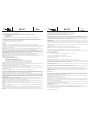
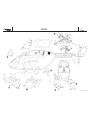
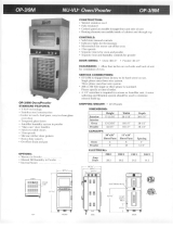
Cut the openings (a - j) in the fuselage using the marked lines as a guide. You can either use a small electric disc-cutter for this, or use a saw and file.
View A shows a typical door glazing panel as an example of the method of fixing the glazing. Cut out the glazing panels (b, c, e and f) leaving a flange about 6
mm wide all round, and trim them to fit in the fuselage. Adjust the window openings if necessary. Trim the front screen (d) to fit in the recess. Both fuselage open-
ings (a) should be left open for better air throughflow and for easy access to the engine for starting.
Note: the glazing panels (b, c, e and f) should be fitted on the inside of the fuselage openings and glued in place with Pattex transparent (clear contact cement)
once the model has been painted. If you install scale cockpit fittings (optional) you may prefer to secure the front screen with 2.2 x 6.5 mm self-tapping screws
(S0042).
The fuselage formers are supplied pre-cut. Assemble the parts „dry“ (without glue) and trim them as necessary until they can be aligned as shown in views B
and C. Carefully glue the parts together using white glue or high-viscosity (thick) cyano. Note that the lateral supports (19) are not glued to the other parts at this
stage; they are fitted when the assembly has been installed and glued in the fuselage. Place the mechanics on the assembly and fit the retaining screws in the
rear holes as shown in view C, detail k. Mark the position of the front attachment point (l), remove the mechanics and drill a 4 mm Ø hole at that point.
View C: epoxy the plastic parts (S3352) to the inside of the openings designed for them. Press M3 captive nuts (S2466) into the outside of the front and rear
formers, force them tightly into the wood and apply epoxy round them for additional security.
Roughen up the rear face of the carrier plate (S1682) and the joint surface inside the fuselage.
View K: adjust the locating holes in the fuselage if necessary, then glue the carrier plate in position using UHU-plus endfest 300.
The following components of the main mechanics have to be replaced:
- Main rotor shaft 186 mm by main rotor shaft 196 mm(S4775)
- Swashplate pushrods [S3203 + S0497] by (S0436 + S0528)
- If necessary tail rotor shaft connector S3300] (for 2 mm Ø steel rod drive shaft) by front coupling (S4742)
- If necessary tail rotor shaft [S3380] (for 2 mm Ø steel rod drive shaft) by tail rotor input shaft (S3705)
Remove the tail boom support [S4325] / [S4606] from the trainer mechanics and fit the spacer [S4136] in its place.
View L: attach the brackets (S1425) to the rear fixing holes of the spacer (S4136 or S4191) using M3 x 45 socket-head cap screws (S1722) and M3 self-lock-
ing nuts (S0012). Press the mechanics holder (S4047) into the spacer .
Drawing D: convert the tail rotor gearbox [S2919] (for 2 mm Ø steel rod drive shaft) to the 24 mm Ø specification [S2977] by fitting the gearbox shells [S4624],
the spacer sleeve [S4833], the self-tapping screws [S4283, S1005] and the tail rotor input shaft [S4747].
Place the prepared wooden former assembly in the fuselage, swivelling it to get it through the top opening. Fit the mechanics and screw the assembly to the for-
mer structure using M4 x 25 and M3 x 25 socket-head cap screws.
Set the assembly central in the fuselage. Tack the wooden parts to the fuselage, check alignment again, then epoxy them in place securely.
Make up the top mechanics attachment as shown in view L . The distance from the mechanics to the fuselage sides may vary slightly depending on the exact
position of the wooden formers. Trim the length of the support (7) in conjunction with the holder (20) and the plywood support, then drill the second mounting
hole. Glue the plywood part to the fuselage in the correct position. Drill 2 mm Ø holes for the holder (20) and screw the holder in place.
Views F + G: slide the skid bars (S1738) into the fuselage, set them central and fix them to the former structure using the plastic parts (S3352) and M3 x 25
socket-head cap screws (S0037). Fit the skid mounting (S1737) onto the skid tubes. Press an M3 self-locking nut (S0012) into each of the skid connectors (8),
with the plastic insert facing out. To fit the skid mountings press a strip of 2 mm plywood 11 x 500 mm into the channel in the skid connectors, and use this as a
tool to slide the connector into the tube until the thread is visible in the hole in the skid mounting. Fit an M3 x 16 socket-head cap screw (S0031) to secure it.
Views G + H: slip the retaining clip (9) on the skid bars (S1738). Press the skid mountings (S1737) onto the skid bars (S1738) and secure them from the rear
with a 2.2 x 6.5 mm self-tapping screw (S0042) after drilling a 1.5 mm Ø pilot hole.
Attach the connecting bracket (10) to the mounting clip using an M3 x 25 socket-head cap screw (S0037) and M3 self-locking nut (S0012), and fix it to the step
with an M3 x 10 countersunk screw (11) and M3 self-locking nut (S0012). Align the parts carefully - note the correct installed height - before tightening the screws.
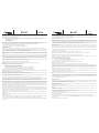
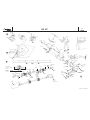
View K: Fit the 20 mm Ø tube (S1684) through the fuselage opening (g) and into the fuselage, then push it into the mechanics holder (S4047) as far as it will
go. Draw a mark on the tube (S1684) 2 mm from the half-clip on the carrier plate (S1682).
View M: remove the tube (S1684) from the fuselage, saw it off at the marked point and file or sand the end flat and square. Use the drilling jig (S2963) as a
clamp for this job.
View L: Remove the mechanics holder (S4047) from the mechanics and glue it to the 20 mm Ø tube (S1684). Drill a 1.5 mm Ø pilot hole and fit a 2.5 x 6.5 mm
self-tapping screw (S1005).
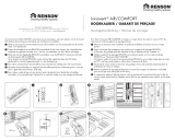
Slide the 6 mm Ø drive tube (S1685) into the drilling jig until one end is flush with it. At this end drill the 2 mm Ø holes A and B in the drive tube using the drilling
jig as a template. Turn the drive tube round in the drilling jig. Open up the outer hole with a file to form a slot and remove all rough edges - C.
Push one coupling claw (S4633) onto the drive tube and secure it with an M2 x 10 screw (S0020). Note the different hole diameters in the coupling claw before
you fit the screw.
View K: slide the drive tube into the fuselage and press the coupling claw (S4633) into the front coupling (S4742) as far as it will go. Draw a mark “MK“
on the drive tube (S1685) 5 mm forward of the carrier plate (S1682).
Remove the drive tube from the fuselage, saw it off at the marked point and file or sand the end flat and square, using the drilling jig (S2963) as a clamp.
Remove the coupling claw.
Drill the 2 mm Ø holes Aand B, and file out the outer hole to form a slot - C.
View N: measure the length of the drive tube (S1685) and mark the positions for the bearing bracket sleeves (S4750). The spacing should be se same.
Apply a little epoxy to the bracket sleeves (S4750) and glue them to the tubular drive shaft (S1685) with the flanges facing each other. Slide the O-rings
(S3544) onto the brackets (S47482) according to the drawing. Fix the ballraces (S01311) attached to the brackets (S47482) to the bracket sleeves
(S4750), again using a little epoxy. Caution: take care to avoid adhesive getting into the ballraces (S01311). Apply Loctite to the coupling claws (S4633),
fit them on the tubular drive shaft (S1685) and secure them with the M2 x 10 cheesehead screws (S0020).
Views P + Q: assemble the 45° gearbox, and trim the bellcrank. Mount the gearbox on the carrier plate using socket-head cap screws and washers,
and fit the bolt and crank.
Slide the 6 mm Ø drive tube (70-1686) into the drilling jig until one end is flush with it. At this end drill the 2 mm Ø holes A and B in the drive tube using
the drilling jig as a template. Turn the drive tube round in the drilling jig. Open up the outer hole with a file to form a slot and remove all rough edges -
C.
Apply Loctite to one coupling claw (S4633), push it onto the drive tube and secure it with an M2 x 10 screw (S0020). Note the different hole diameters
in the coupling claw before you fit the screw.
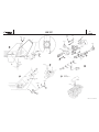
Fit the drive tube in the integral vertical stabiliser and engage the coupling claw in the 45° gearbox.
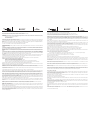
View Q: glue the tail rotor bulkhead (S4046) in the fuselage at a distance of 44 mm from the front edge of the vertical stabiliser.
View R: fit the 2.2 x 6.5 mm self-tapping screws (S0042) and the washers (S0000) for additional security.
Fit the second coupling claw on the plain end of the drive tube (70-1686) and engage the tail rotor gearbox. Measure dimension „Y“ from the tail rotor
bulkhead to the mounting surface of the tail rotor gearbox.
View M1: please note the when cutting the tube to length:
- 24 mm Ø tail rotor [S2977]: use the drilling jig, and shorten the drive tube by dimension „Y“ + 1 mm.
Drill the 2 mm Ø holes Aand B, and file out the outer hole to form a slot - C.
Fit the second coupling claw (not forgetting the Loctite) and secure it with an M2 x 10 screw (S0020).
Remove the 45° gearbox from the fuselage.
View A: glue the horizontal stabiliser (12) in slot H, checking that it is exactly central. Glue the vertical stabilisers (13) to it.
Trim the fuselage hatch (16) to fit in the top fuselage opening and drill 1.5 mm Ø holes through both parts. Cut out the gearbox cover (17) following the
marked lines, tape it in place centrally and drill through the cover and fuselage as before. Strips of plywood are used to reinforce the fuselage cover;
glue them under the edge of the fuselage and continue the holes through the ply. Open up the holes in the fuselage cover and the gearbox cover to 2
mm Ø.
Fix the fuselage cover (16) and the gearbox cover (17) to the fuselage using 2.2 x 6.5 mm self-tapping screws (S0042) and washers (S0000), but not
until the mechanics assembly has been installed permanently.
Drill holes for the door handles, aerials, screen wipers and hand-holds at the points shown. Install the detail fittings, ventilation grilles and steps before
or after painting the model, depending on your choice of colour scheme.
View S: cut an opening in the side support (19) and the underside of the fuselage to clear the exhaust extension. Glue the support to the former struc-
ture.
Examine the fuselage joint seams and sand them lightly where necessary. Apply several coats of primer to the wooden parts, sanding smooth between
coats. Apply fuel-proofer to prevent the parts absorbing oil and fuel. The fuselage can now be painted. We recommend only synthetic enamel paints for
this model. Important: be sparing with the paint, as pigment is heavy and you need to keep an eye on the model’s all-up weight. It is very easy to add
several hundred grammes of weight in this way!
Installing the mechanics
Lightly grease the coupling claws (S4633), then oil the mating surfaces and slide the complete rigid drive system and jig tube into the tail boom (S1684).
Complete the 20 mm Ø tube (S1684) by fitting the servo mounts (S0940) and servo, the pushrod guides (S1241), and the two-part pushrod (S0375,
S3477) complete with pushrod connector (S1242) and clevises (S0059).
View L: place this assembly in the fuselage. Press the mechanics holder (S4047) in the mechanics spacer and screw it to the bracket (5) together with
the top mechanics attachment.
Connect the tail rotor servo to the receiver or gyro.
Views P + Q: fix the rear end of the 20 mm Ø tube (S1684) to the carrier plate (S1682) using the clip (S4371) and M3 x 14 socket-head cap screws
(S3198).
Install the 45° gearbox, engaging the coupling claws on the drive tube (S1685) in the mechanics and the 45° gearbox as you do so. Connect the clevis
to the lever on the angle gearbox.
Grease the claws of the coupling attached to the drive tube (S1686) and fit it in the vertical stabiliser together with the tail rotor gearbox. Engage the
coupling claws in the 45° angle gearbox and the tail rotor gearbox at the same time.
Tighten the tail rotor gearbox retaining screws.
Fit clevises to both ends of the pushrod (S3452), fit the pushrod in the vertical stabiliser and connect it to the lever on the 45° angle gearbox and the
bellcrank on the tail rotor gearbox.
When fitting the tail rotor [S2977] you will need to drill four 6 mm Ø holes in the vertical stabiliser to allow access to the tail rotor bulkhead.
If you are using the two-blade rotor head it is essential to fit the longer flybar (S4516) supplied in the kit. We also recommend installing a set of iner-
tia weights [S0755].
We reserve the right to alter technical specifications.
4 5

BK 117
No.
S 2918
Vue K: engager le tube d’entraînement dans le fuselage et presser la griffe (S4633) jusqu’en butée dans l’accouplement avant (S4742). Munir le tube
d’entraînement (S1685) d’un repère “MK“, 5 mm avant la plaque-support (S1682).
Retirer le tube d’entraînement du fuselage et scier au niveau du repère avant de limer ou de poncer à plat.
Pour ce faire, utiliser le gabarit de perçage (S2963) comme dispositif de bridage. Retirer la griffe d’accouplement.
Percer les trous de 2 mm de diamètre Aet B. Ouvrir le trou extérieur en fente - C.
Vue N: mesure la longueur du tube de 6 mm ø et marquer la position pour les manchons porte-palier (S4750) à écart symétrique.
Coller les manchons porte-palier (S4750) avec l’épaulement de chacun d’eux avec de la colle époxy sur le tube de transmission (S1685). Enfiler les
joints toriques (S3544) sur les porte-palier (S47482) selon le croquis. Coller également les roulements à billes (S01311) des porte-palier (S47482) avec
un peu de colle époxy sur les manchons porte-palier (S4750). Attention : veiller à ce que la colle ne s’introduise pas dans les roulements à billes
(S01311). Engager les mâchoires d’accouplement (S4633) sur le tube de transmission (S1685) avec du Loctite et l’y fixer avec les vis à tête cylindrique
M 2 x 10 (S0020).
Vues P + Q: monter le mécanisme à 45°. Traiter le palonnier de renvoi selon les indications du schéma complémentaire. Fixer le mécanisme avec les
vis six pans creux, les rondelles, les axes et palonnier à la plaque-support.
Glisser le tube d’entraînement de 6 mm de diamètre (70-1686) dans le gabarit de perçage de telle manière qu’une extrémité soit à fleur. À cette
extrémité, percer les trous de 2 mm A et B selon les indications du gabarit de perçage. Retourner le tube d’entraînement dans le gabarit de perçage.
Ouvrir le trou extérieur en fente en limant et l’ébarber - cf. détail C du schéma complémentaire.
Planter une griffe d’accouplement (S4633) enduite de Loctite sur le tube d’entraînement et bloquer avec la vis M 2 x 10 (S0020). Lors du serrage, observ-
er les divers diamètres de trous de la griffe de serrage.
Planter le tube d’entraînement dans la dérive du fuselage et accoupler la griffe d’accouplement au mécanisme à 45°.
Vue Q: coller le couple de rotor arrière (S4046) dans le fuselage avec un écart de 44 mm par rapport à l’arête avant de la dérive.
Vue R: fixer le couple du rotor arrière en place avec les vis autotaraudeuses 2,2 x 6,5 mm (S0042) et les rondelles (S0000).
Planter la seconde griffe d’accouplement dans l’extrémité libre du tube d’entraînement (70-1686). Accoupler le mécanisme du rotor arrière. Mesurer la
cote „Y“ entre le couple du rotor arrière et le support du mécanisme du rotor arrière.
Vue M1: Tenir compte de nuances suivantes lors du raccourcissement
- Rotor arrière de 24 mm de diamètre [S2977]: raccourcir le tube d’entraînement de la cote „Y“ + 1 mm, à l’aide du gabarit de perçage.
Percer les trous Aet B de 2 mm de diamètre. Ouvrir le trou extérieur en fente en le limant - cf. C
Planter la seconde griffe d’accouplement avec du Loctite et la bloquer avec la vis M 2 x 10 (S0020).
Déposer la mécanique à 45° du fuselage.
Vue A: coller le stabilisateur (12) au centre de la découpe H. Mettre le stabilisateur (13) en place et le coller également.
Ajuster le couvercle du fuselage (16) dans l’ouverture supérieure du fuselage et le percer avec le fuselage (foret de 1,5 mm). Découper le couvercle du
mécanisme (17) selon les repères, le fixer au centre et le percer également avec le fuselage. Coller les bandes de contreplaqué pour renforcer le cou-
vercle du fuselage sous l’arête du fuselage et les percer également. Porter les trous dans le couvercle du fuselage et dans le couvercle du mécanisme
à 2 mm de diamètre.
Fixer le couvercle du fuselage (16) et le couvercle du mécanisme (17) au fuselage avec les vis autotaraudeuses 2,2 x 6,5 (S0042) et les rondelles
(S0000) après avoir achevé le montage de la mécanique.
Percer les trous pour la fixation des poignées de porte, les antennes, les essuie-glace et les poignées de maintien aux emplacements indiqués. En fonc-
tion de la mise en peinture du modèle, coller les éléments de décoration, calandres et marchepieds avant ou après.
Vue S: munir le support latéral (19) et la partie inférieure du fuselage d’une ouverture pour la rallonge de pot d’échappement. Coller le support sur la
structure des couples.
Ajuster et poncer, si nécessaire. Apprêter plusieurs fois les éléments de bois et les poncer. Les protéger contre les projection de carburant avec de la
peinture. Peindre le fuselage. N’utiliser que des peintures à base de résine synthétique. Attention: ne pas appliquer trop de peinture. Un excès de pein-
ture risque en effet d’accroître inutilement le poids du modèle. On applique rapidement plusieurs centaines de grammes !
Mise en place de la mécanique
Graisser légèrement les mâchoires d’accouplement (S4633) et introduire la transmission rigide complète avec le tube auxiliaire de montage dans la
flèche du rotor arrière (S1684) en employant un peu de lubrifiant.
Équiper le tube de 20 mm de diamètre (S1684) des support-servo (S0940) avec servo, des guide-tringle /S1241), des tringles en deux parties (S0375,
S3477) avec raccord (S1242) et des chapes (S0059).
Vue L:engager l’unité dans le fuselage. Planter le porte-mécanique (S4047) dans l’entretoise de la mécanique et fixer ensemble avec la fixation
supérieure de la mécanique à l’équerre de maintien (5).
Raccorder le servo du rotor arrière au récepteur et à l’Autopilote.
Vues P + Q: fixer l’extrémité arrière du tube de 20 mm de diamètre (S1684) avec le collier (S4371) et les vis six pans creux M 3 x 14 (S3198) à la plaque-
support (S1682).
Installer l’engrenage à 45° en engageant les griffes d’accouplement du tube d’entraînement (S1685) dans la mécanique et dans l’engrenage à 45°.
Accrocher la chape au palonnier de renvoi de l’engrenage.
Graisser légèrement les griffes d’accouplement du tube d’entraînement (S1686) et l’installer avec le mécanisme arrière dans la dérive en enclenchant
les griffes d’accouplement dans l’engrenage à 45° et l’engrenage arrière.
Fixer l’engrenage arrière.
Munir la tringle (S3452) des chapes, l’engager dans la dérive et la relier au palonnier de l’engrenage à 45° et au palonnier de renvoi du mécanisme
arrière.
Si c’est le rotor arrière [S2977] qui est mis en place, il faut pour la fixation au couple du rotor arrière percer quatre trous de 6 mm de diamètre dans la
dérive.
Si le rotor mis en place est un rotor bipale, il faut absolument installer la barre stabilisatrice la plus longue (S4516) fournie dans le kit. Il est recom-
mandé d’utiliser un jeu de contrepoids [S0755].
Sous réserve de modification technique.
7
BK 117
No.
S 2918
Ce kit fuselage BK 117 est conçu pour équiper une mécanique du fuselage FUTURA en liaison avec le kit de transformation au 1/10e [S2931] et le moteur à
essence ZG23. Pour le ZG 23, il faut par ailleurs acquérir le silencieux [S0906] et la rallonge de pot d’échappement BK 117 [S2946].
Les pièces présentées entre crochets [ ] ne font pas partie de la boîte de construction.
Il faut par ailleurs acquérir le silencieux [S0906] et la rallonge de pot d’échappement BK 117 [S2946].
Si le mécanisme de transmission du rotor arrière [S2919] (pour tige de transmission de Ø 2 mm) est installé sur le rotor arrière Ø 24 mm [S2977]
il faut en plus:
- un carter de rotor arrière droit et gauche [S4624]
- manchon entretoise [4833]
- un accouplement arrière [S747].
Pour la tête rotor à deux pales, il est recommandé d’utiliser les pales de rotor principal en résine époxy renforcé fibre de verre à centre de gravité corrigé
[S2939 rotation vers la droite] ou [S2940 rotation vers la gauche].
Le rotor quadripale [S2914] ne doit être mis en œuvre qu’avec les pales en résine époxy renforcé fibre de verre à centre de gravité corrigé correspondantes.
Il faut, par ailleurs, y joindre l’entraîneur de plateau cyclique [S2802], un pivot sphérique M 2,5 x 6 [S4442], 4 tringles M 2,5 x 60 [S3589] et 8 biellettes 2,5
[S3083].
Les pales de rotor arrière longues (bois, 140 mm de long) sont disponibles sous la référence S3955.
Pour coller, nous recommandons les colles UHU-plus endfest 300 et robbe ropoxi [5066].
Aménagement du fuselage
Selon les repères portés sur le fuselage, pratiquer les ouvertures (a-j). Cette opération peut être réalisée en sciant, en limant ou à l’aide d’une petite fraise
électrique.
Comme donné en exemple pour la fenêtre de la porte sur le détail A, découper les vitrages (b, c, e, f) avec une marge d’environ 6 mm et les ajuster au fuse-
lage. Reprendre éventuellement les ouvertures. Ajuster le pare-brise (d) dans l’épaulement. Les deux ouvertures (a) resteront de préférence ouvertes pour
assurer un meilleur refroidissement du moteur et faciliter son démarrage.
Attention: les vitres (b, c, e, f) seront ultérieurement, après mise en peinture, installées par l’intérieur dans les ouvertures du fuselage et collées en bordure
(colle Pattex transparente). Si vous aménagez la cabine à vos goûts, il est également possible de fixer le pare-brise avec des vis autotaraudeuses 2,2 x 6,5
(S0042).
Le jeu de couples est déjà découpé. Les assembler pour en vérifier l’ajustement et les retoucher éventuellement, puis, comme indiqué sur les détails B et
C, les centrer et les coller avec soin (colle blanche ou cyanoacrylate épaisse). Les deux supports latéraux (19) ne seront cependant installés et collés qu’après
mise en place dans le fuselage et collage effectif de la structure des couples. Mettre la mécanique en place et la fixer aux alésages de fixation arrière (sché-
ma C, détail k). Reporter le point de fixation avant (l), retirer la mécanique et percer avec une mèche de 4 mm.
Schéma C: installer les éléments de plastique (S3352) de l’intérieur dans les découpes prévues et les coller avec de la colle époxy. Planter les écrous noyés
M 3 (S2466) de l’extérieur dans le couple arrière et couple avant, les serrer dans le bois à l’aide de vis et les bloquer ensuite avec de la résine époxy.
Poncer la face arrière de la plaque-support (S1682) et la zone de collage du fuselage.
Vue K: reprendre éventuellement l’alésage de centrage dans le fuselage et coller la plaque-support avec de la colle UHU-plus endfest 300.
Remplacer les éléments de la mécanique suivants par les éléments du kit:
- arbre de rotor principal 186 mm par arbre de rotor principal 196 mm (S4775)
- tringlerie du plateau cyclique [S3203+S0497] par (S0436+S0528)
- si nécessaire, le raccord de rotor arrière [S3300] (pour tige de transmission de Ø 2 mm) par l’accouplement avant (S4742)
- si nécessaire, l’arbre de rotor arrière [S3380] (pour tige de transmission de Ø 2 mm) par l’arbre d’admission du rotor arrière (S3705).
Sur les mécaniques d’entraînement remplacer le palier de rotor arrière [S4325] / [S4606] par l’entretoise [S4136].
Vue L: fixer les équerres de maintien (S1425) aux trous arrière de l’entretoise (S4136 ou S4191) avec les vis six pans creux M3 x 45 (S1722) et les écrous
autobloquants M3 (S0012). Planter le porte-mécanique (S4047) dans l’entretoise.
Schéma D: transposer le mécanisme arrière [S2919] (pour tige de transmission de Ø 2 mm) avec les coquilles de carter [S4624], le manchon entretoise
[S4833], les vis autotaraudeuses [S4283, S1005] et l’arbre d’entrée arrière [S4747] sur le mécanisme du rotor arrière Ø 24 mm [S2977]
Faire pivoter la structure des couples préparée par l’ouverture supérieure du fuselage, mettre la mécanique en place et la fixer à la structure des couples (vis
six pans creux M 4 x 25 + M 3 x 25).
Centrer parfaitement l’unité, fixer la structure des couples au fuselage avec de la coller avec soin à l’aide de résine époxy.
Réaliser la fixation supérieure de la mécanique selon les indications de la vue L. En fonction de la mise en place des couples, l’écart de la mécanique par
rapport à la paroi du fuselage peut être différent. Ajuster la longueur du support (7) dans le raccord avec support (20) et l’embase de contreplaqué, percer le
second trou. Coller le contreplaqué à l’emplacement correspondant du fuselage. Réaliser les trous de 2 mm pour le support (20) et visser le support.
Vues F + G: glisser l’étrier de patins (S1738) dans le fuselage, le centrer et le fixer aux couples avec les éléments de plastique (S3352) et les vis six pans
creux M 3 x 25 (S0037). Planter la fixation de patin (S1737) sur les tubes de patins. Presser chaque fois un écrou autobloquant M 3 (S0012) dans les rac-
cords de patin (8) (garniture de plastique de l’écrou vers l’extérieur). Pour monter la fixation des patins, presser une bande de contreplaqué 11 x 2 x 500 mm
dans L’encoche du raccord de patin, et, avec son aide, glisser le raccord de patin dans le tube jusqu’à ce que le filetage devienne visible dans l’alésage du
raccord de patin. Mettre la vis six pans creux M 3 x 16 (S0031) en place.
Vues G + H: glisser le collier de fixation (9) sur l’étrier de patin (S1738). Presser les fixations de patin (S1737) sur l’étrier de patin (S1738) et le bloquer de
l’arrière avec la vis autotaraudeuse 2,2 x 6,5 (S0042), prépercer d’abord avec une mèche de 1,5 mm.
Selon les indications de la vue H, fixer l’équerre de raccordement (10) avec la vis six pans creux M 3 x 25 (S0037) et l’écrou autobloquant M 3 (S0012) au
collier de fixation et avec la vis à tête fraisée M 3 x 19 (11) et l’écrou autobloquant M 3 (S0012) au marchepied, centrer et serrer (attention à la hauteur de
vissage).
Vue K: engager le tube de 20 mm de diamètre (S1684) dans l’ouverture du fuselage (g) et le glisser jusqu’en butée dans le porte-mécanique (S4047).
Appliquer un repère sur le tube (S1684) avec un écart de 2 mm par rapport au demi-collier de la plaque-support (S1682).
Vue M: retirer le tube (S1684) du fuselage, le scier au niveau du repère et le limer à plat ou le poncer à plat. Pour ce faire, utiliser le gabarit de perçage
(S2963) comme auxiliaire de bridage.
Vue L: retirer le porte-mécanique (S4047) de la mécanique et le coller au tube de 20 mm de diamètre (S1684). Bloquer en plus le collage avec la vis 2,5 x
6,5 (S1005), prépercer avec une mèche de 1,5 mm.
Glisser le tube d’entraînement de 6 mm de diamètre (S1685) dans le gabarit de perçage de telle manière qu’il soit à fleur avec une extrémité. À cette extrémité,
percer les trous de 2 mm A et B selon les indications du gabarit de perçage. Retourner le tube d’entraînement dans le gabarit de perçage. Ouvrir le trou
extérieur en fente en limant et l’ébarber - cf. détail C.
Planter une griffe d’accouplement (S4633) sur le tube d’entraînement et bloquer avec la vis M 2 x 10 (S0020). Lors du serrage, observer les divers diamètres
de trous de la griffe de serrage.
6

BK 117
No.
S 2918
Ø 4 mm
S0000
S0042
Ø 1,5 mm
6 mm
Ø 4 mm
S1737
S1729
S1738
S1728
S1738
S1728
S1738
S0037
S3352
95 mm
S3352
S0042
S0000
5 mm
S0031
S0042
S1737
S0012
S1728
S0012
S0012
S0037
S1738
A
C
B
F
H
G
S2466
S2466
robbe Form 70-3864 GAB
D
S4283
S4624
S1005
S4624
S4486
S0249
S4747
S4833
S4303
S4303
S2977
(16)
(4)
(6)
(5)
(13)
(12)
(17)
(8)
(9)
(10)
(11)
(19)
(19)
(19)
(19)

BK 117
No.
S 2918
K
1/3
S4750
S4750
S1685
S1685
S1684
S3544
S3544
S3544
S3544
S0020
S0020
S4633
S4633
Hilfsrohr
Jig tube
Tube auxiliaire
S01311
S01311
S4750
S4750
S47482
S47482
Für Rohr
For tube Ø 20 x 0,5
Pour tube
d
D
Bitte beachten:
Please note: d < D
À noter:
1/3
1/3
N
S1682
S4375
Ø 2 mm
S2963
M
S0059
S1242
S3477
S3705
S1005
S1241
S1684
S0375
S0059
S4375
S0940
S0077
S4742
S0012
S4047
S1005
S1722
S4047
S0010
S0000
S0020
S3198
M3x14
L
2 mm
5 mm
1
0
m
m
1
0
m
m
6
m
m
6
m
m
1
m
m
S4047
S4136
S4191
S1684
S4136
S4191
„MK“
robbe Form 70-14092 GAB
(20)
(7)
(7)
(5)
(5)
(5)
„MK“
S0039
M3x10

BK 117
No.
S 2918
S0042
S0000
S0042
S0000
S4046
1,5 mm
5 mm
4
4
m
m
S3452
S0020
M2x10
S0020
M2x10
70-1686
S4633
S4633
Ø 2 mm
+
1
m
m
Y
S3705
S3198
M3x14
S4371
S1682
S1680
S1641
S1680
S0001
S0037
S4303
S4303
S3705
S1681
S0041
S0007
S0038
S1687
R
P
Q
M1
S
nur ZG 23
ZG 23 only
seulement ZG 23
S0906
S2946
robbe Form 70-14092 GAB
20-5530
(13)
(12)
(17)
(1)
(15)

robbe Modellsport GmbH & Co. KG
Metzloserstr. 36
Telefon 06644 / 870
36355 Grebenhain
robbe Form 70-14091 FAB
-
 1
1
-
 2
2
-
 3
3
-
 4
4
-
 5
5
-
 6
6
-
 7
7
-
 8
8


ROBBE BK 117 Assembly And Operating Instructions Manual
- Catégorie
- Jouets
- Taper
- Assembly And Operating Instructions Manual
dans d''autres langues
- English: ROBBE BK 117
- Deutsch: ROBBE BK 117
Documents connexes
Autres documents
-
 Nu-Vu Food Service System OP-3/9M Fiche technique
-
 Renson Invisivent COMFORT Ultra Guide d'installation
-
Parkside PSVH 56 A1 Operating Instructions Manual
-
MULTIPLEX Domino Le manuel du propriétaire
-
-
-
-
-
Equipex EP800 Le manuel du propriétaire
-
 Graine créative 14131260 Mode d'emploi


