
NCR59722x20Customer
Display
Release2.0
UserʹsGuide
BD20‐1372‐A
IssueF

TheproductdescribedinthisbookisalicensedproductofNCRCorporation.
NCRisaregisteredtrademarkofNCRCorporation.
ItisthepolicyofNCRCorporation(NCR)toimproveproductsasnewtechnology,components,software,
andfirmwarebecomeavailable.NCR,therefore,reservestherighttochangespecificationswithoutprior
notice.
Allfeatures,functions,andoperationsdescribedhereinmaynotbemarketedby
NCRinallpartsofthe
world.Insomeinstances,photographsareofequipmentprototypes.Therefore,beforeusingthisdocument,
consultwithyourNCRrepresentativeorNCRofficeforinformationthatisapplicableandcurrent.
Tomaintainthequalityofourpublications,weneedyourcommentsontheaccuracy,clarity,
organization,
andvalueofthisbook.
Addresscorrespondenceto:
Manager,InformationProducts
NCRCorporation
2651SatelliteBlvd.
Duluth,GA30096
Copyright©1999
ByNCRCorporation
Dayton,OhioU.S.A.
AllRightsReserved

Preface
Thismanualisforhardwareinstaller/servicepersonnel,system
integrators,fieldengineers,andprogrammers.
Safety Requirements
Warning: This device does not contain any user serviceable parts
and should only be serviced by a qualified service technician.
Caution: Thisdeviceshouldonly bepoweredbya(SELV)Safety
ExtraLowVoltagepowersupplysourcewithanavailablepowerlevel
of5amperesorless,andsuitableforthecountry ofinstallation.The
powersourcemustbecertifiedbytheappropriatesafetyagencyforthe
countryofinstallation.
LematérieldoitêtrereliéselectriquementaucircuitåTrèsBasse
TensiondeSécurité(TBTS)ayantunelimitede5ampères
correspondantdefaçonsatisfaisanteetacceptabledanslepaysoùle
matérieldoitêtreinstallé.Lesourced’alimentationdoitêtreapprovée
paruneagencedenormalisationappropriéeetacceptable
danslepays
oùlematérieldoitêtreinstallé.
Caution: Forcontinuedprotectionagainstriskoffire,replaceonly
withthesametypeandratingsoffuse.
Pourpréveniretvousprotégercontreunrisquedefeu,remplacerla
fusibleavecuneautrefusibledemêmetype,seulement.
Caution: Thepowersupply
cordisusedasthemaindisconnect
device.Ensurethatthesocketoutletislocated/installednearthe
equipmentandiseasilyaccessible.
Lecordond’alimentationestutilisécommeinterrupteurgénéral.La
prisedecourantdoitetrêsituéeouinstalléeaproximitédumatérielet
êtrefaciled’accés.

0-2 Chapter 1: Introduction

Chapter 1: Introduction 0-3
Table of Contents
Chapter1:Introduction
Models ....................................................................................................1‐1
Features ..................................................................................................1‐1
VFDModels ....................................................................................1‐1
Hardware ....................................................................................1‐1
Software.......................................................................................1‐2
LCDModels ....................................................................................1‐3
Hardware ....................................................................................1‐3
Software.......................................................................................1‐3
Chapter2:SitePreparation
PhysicalEnvironment ..........................................................................2‐1
WorkingRange ...............................................................................2‐1
StorageEnvironment .....................................................................2‐2
TransitEnvironment ......................................................................2‐2
Dimensions......................................................................................2‐3
VFDModels ................................................................................2‐3
LCDModels................................................................................2 ‐6
ElectricalEnvironment.........................................................................2‐7
VFDACPowerRequirements......................................................2‐7
VFDDCPowerRequirements......................................................2‐7
LCDACPowerRequirements......................................................2‐7
LCDDCPowerRequirements......................................................2‐7
OperationalEnvironment....................................................................2‐7
SystemConfiguration ....................................................................2‐7
MountingHoleDimensions ................................................................2‐8

0-4 Chapter 1: Introduction
Chapter3:Installation
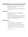
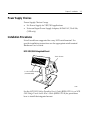
InstallingtheCustomerDisplay .........................................................3‐1
SELVPowerSourceWarning .......................................................3‐1
InstallationGoal..............................................................................3‐2
CableRequirements .......................................................................3‐2
PowerSupplyChoices...................................................................3‐3
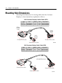
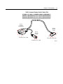
InstallationProcedures ..................................................................3‐3
NCR5952/5962IntegratedMount ...........................................3‐3
RS‐232SerialInterface ...............................................................3‐4
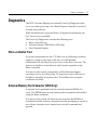
Diagnostics.............................................................................................3‐5
Micro‐controllerTest......................................................................3‐5
ExternalMemoryTestCharacter(VFDOnly)............................3‐5
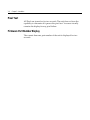
PixelTest..........................................................................................3‐6
FirmwarePartNumberDisplay...................................................3‐6
Chapter4:ProgrammingSetUp
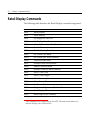
Host/RetailDisplayCommandInterface ..........................................4‐1
RetailDisplayCommands...................................................................4‐2
ResetDisplay...................................................................................4‐4
EraseDisplay...................................................................................4‐5
SetDiagnosticStateOn ..................................................................4‐5
SetDisplayStateOn.......................................................................4‐6
SetLowPowerStateOn ................................................................4‐6
EnableCursor..................................................................................4‐7
DisableCursor ................................................................................4‐7
SetScreenSaveBlank.....................................................................4‐8
SetScreenSaveWalk .....................................................................4‐8
TurnOnScreenSave......................................................................4‐9
DisableScreenSaveOption ..........................................................4‐9

Chapter 1: Introduction 0-5
EnableCharacterBlink ..................................................................4‐9
DisableCharacterBlink ...............................................................4‐10
MoveCursorLeft..........................................................................4‐10
MoveCursorRight.......................................................................4‐10
MoveCursorUp ...........................................................................4‐11
MoveCursorDown ......................................................................4‐11
MoveCursorToSpecifiedPosition ...........................................4‐12
BrightnessAdjustment ................................................................4‐13
ReadDisplayIDByte...................................................................4‐13
ReadDisplayIDString ................................................................4‐14
DisplayESCCharacter.................................................................4‐14
SelectCharacterSetn...................................................................4‐14
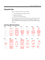
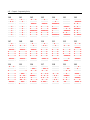
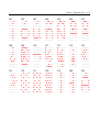
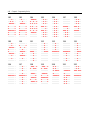
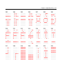
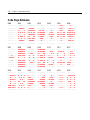
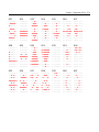
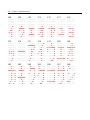
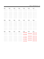
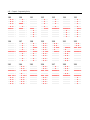
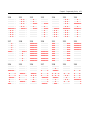
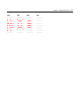
CharacterSets ......................................................................................4‐15
CodePage850(International) ....................................................4‐15
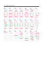
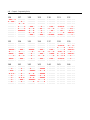
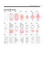
CodePageKatakana ....................................................................4‐28
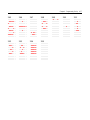
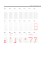
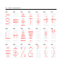
CodePage866(Cyrillic) ..............................................................4‐41
Chapter5:Service
SafetyRequirements.............................................................................5‐1
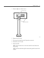
ServicingtheDisplay............................................................................5‐3
NormalOperation ..........................................................................5‐3
TroubleshootingProcedures.........................................................5‐3
ServicingtheVFDorLCD.............................................................5‐4
CleaningtheDisplay......................................................................5 ‐6

0-6 Chapter 1: Introduction
Revision Record
Issue Date Remarks
A Feb97 Firstissue
B Nov98 Updatetoinclude5972‐1100
C Mar99 Added5963IntegratedDisplayMount
D Jan03 Removed5972‐2x00model.Addeddimension
information.
E Feb03 Addedcharactersets.
F June03 AddednewLCDmodels

Chapter 1: Introduction 0-7
Radio Frequency Interference Statements
Federal Communications Commission (FCC)
InformationtoUser
ThisequipmenthasbeentestedandfoundtocomplywiththelimitsforaClassA
digitaldevice,pursuanttoPart15ofFCCRules.Theselimitsaredesignedtoprovide
reasonableprotectionagainstharmfulinterferencewhentheequipmentisoperatedin
acommercialenvironment.Thisequipmentgenerates,uses,andcan
radiateradio
frequencyenergyand,ifnotinstalledandusedinaccordancewiththeinstruction
manual,maycauseharmfulinterferencetoradiocommunications.Operationofthis
equipmentinaresidentialareaislikelytocauseinterferenceinwhichcasetheuser
willberequiredtocorrecttheinterferenceathisownexpense.
NCRisnotresponsibleforanyradioortelevisioninterferencecausedbyunauthorized
modificationofthisequipmentorthe substitutionorattachmentofconnectingcables
andequipmentotherthanthosespecifiedbyNCR.Thecorrectionofinterference
causedbysuchunauthorizedmodification,substitutionorattachmentwillbethe
responsibility
oftheuser.Theuseriscautionedthatchangesormodificationsnot
expresslyapprovedbyNCRmayvoidtheuser’sauthoritytooperatetheequipment.
Canadian Department of Communications
ThisdigitalapparatusdoesnotexceedtheClassAlimitsforradionoiseemissions
fromdigitalapparatussetoutintheRadioInterferenceRegulationsoftheCanadian
DepartmentofCommunications.
Leprésentappareilnumériquen’émetpasdebruitsradioélectriquesdépassantles
limitesapplicablesauxappareilsnumériquesdelaclasseAprescrites
dansle
Règlementsurlebrouillageradioélectriquesédictéparleministrèredes
CommunicationsduCanada.
Voluntary Control Council For Interference (VCCI)

0-8 Chapter 1: Introduction

Chapter 1: Introduction
Models
TheNCR5972CustomerDisplayisdesignedtobeanoptionaldisplay
devicefortheNCRretailterminals.Itcanalsoserveasadisplayfor
anyindustry‐standardPC.ItisaVacuumFluorescentDisplay(VFD).
• 5972‐10002x20VFD(LightGray)
• 5972‐11002X20VFD(DarkGray,
LowPostMount)
• 5972‐12002x20VFD(LightGray,EuroSymbol)
• 5972‐13002x20VFD(DarkGray,LowPostMount)
• 5972‐14002x20VFD(CharcoalGray,LowPostMount)
• 5972‐24002x20LCD(LightGray,1mCable)
• 5972‐25002x20LCD(LightGray,4mCable)
Features
VFD Models
Hardware
• ParallelI/ForEIA‐232I/Fsupport
• Thecomponentsforbothinterfacesarepopulatedonone
printedcircuitboard.Bothinterfaces areactive,thoughonly
oneinterfacecanbephysicallyconnectedatatime.Thedisplay
communicatesviatheinterfaceconnectedtoit.
• Socketfor32KofPROM
foradditionalcharactersets
• Cables

1-2 Chapter 1: Introduction
• PowerSupply
• MountingOptions
TableMount,LightGray,16‐in.Post
TableMount, LightGray,8‐in.Post
TableMount,LightGray,NoPost
• RemoteMount,8‐in.Post,LightGray
• RemoteMount,8‐in.Post,DarkGray
• IntegratedMount,
TelescopingPost,CharcoalGrayfor7458
• IntegratedMount,TelescopingPost,LightGrayfor5964
• IntegratedMount,TelescopingPost,LightGray
• NoMount
Software
• VFDcontrolof7x9pixelcharacters
• ParallelI/F
• EIA‐232SerialI/F(9600BPS,8bitcharacter,noparity,1stopbit)
• Diagnostics
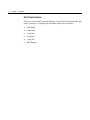
• Supportfor19charactersets
• 3Charactersetsinbaseunit
• CodePage858(International)
• Katakana
• CodePage866(Cyrillic)
• Socketallowsforsupportofupto16additional charactersets

Chapter 1: Introduction 1-3
LCD Models
Hardware
• Cables
• PowerSupply
• MountingOptions
TableMount,LightGray,16‐in.Post
TableMount,LightGray,8‐in.Post
TableMount,LightGray,NoPost
• RemoteMount,8‐in.Post,LightGray
• IntegratedMount,TelescopingPost,LightGrayfor5964
• IntegratedMount,TelescopingPost,LightGray
• NoMount
Software
• PoweredRS‐232I/F
• Diagnostics
• 1Charactersetinbaseunit
• CodePage858(International)

1-4 Chapter 1: Introduction

Chapter 2: Site Preparation
Thischapterdescribestheinstallationprocessincludingsite
considerations,operatingconditions,mountingoptions,and
connections.
Physical Environment
Theworkingrange,storage,andtransitenvironmentsarepresentedin
thefollowingtables.
Working Range
Condition Range
Tem
p
erature 10°Cto40°C
(
50°Fto104°F
)
Tem
p
eratureChan
g
e 10°C(18°F)/Hour
Humidit
y
Ran
g
e 20%to80%(NoCondensation)
Humidit
y
Chan
g
e 10%/hour
BarometricPressure 105,000Pato69000Pa
Note: Condensationmayoccurwhenequipmentistransferredfrom
coldtowarmareasduringshipment.Theequipmentdesignshall
permitoperationaftercondensationhasoccurred,adryingoutprocess
hasbeenaccomplished,andtheequipmentstabilizedtotheoperating
environment.

2-2 Chapter 2: Site Preparation
Storage Environment
Forperiodsuptothreemonths:
Condition Range
Tem
p
erature‐10°Cto50°C
(
14°Fto120°F
Humidit
y
10%to90%RH
BarometricPressure 105,000to70,000Pa
Transit Environment
Forperiodsuptooneweek:
Condition Range
Tem
p
erature‐40°to60°C
(
‐40°Fto140°F
)
Humidit
y
5%to95%RH
BarometricPressure 105,000to70,000Pa

Chapter 2: Site Preparation 2-3
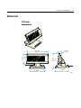
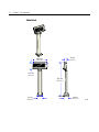
Dimensions
VFD Models
Desktop Mount
17241
262 mm
(10.3 in.)
162 mm
(6.4 in.)
173 mm
(6.8 in.)
119 mm
(4.7 in.)
30 mm
(1.2 in.)
178 mm
(7.0 in.)

2-4 Chapter 2: Site Preparation
16-Inch Post
262 mm
(10.3 in.)
15708
95 mm
(3.75 in.)
561 mm
(22.1 in.)
30 mm
(1.2 in.)
119 mm
(4.7 in.)
95 mm
(3.75 in.)

Chapter 2: Site Preparation 2-5
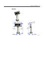
8-Inch Post
20131a
95 mm
(3.75 in.)
356 mm
(14.1 in.)
262 mm
(10.3 in.)
119 mm
(4.7 in.)
356 mm
(14.1 in.)
30 mm
(1.2 in.)
95 mm
(3.75 in.)

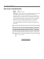
2-6 Chapter 2: Site Preparation
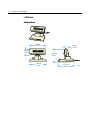
LCD Models
Desktop Mount
15412
173 mm
(6.8 in.)
139 mm
(5.5 in.)
30 mm
(1.2 in.)
178 mm
(7.0 in.)
68 mm
(2.6 in.)
178 mm
(7.0 in.)
La page est en cours de chargement...
La page est en cours de chargement...
La page est en cours de chargement...
La page est en cours de chargement...
La page est en cours de chargement...
La page est en cours de chargement...
La page est en cours de chargement...
La page est en cours de chargement...
La page est en cours de chargement...
La page est en cours de chargement...
La page est en cours de chargement...
La page est en cours de chargement...
La page est en cours de chargement...
La page est en cours de chargement...
La page est en cours de chargement...
La page est en cours de chargement...
La page est en cours de chargement...
La page est en cours de chargement...
La page est en cours de chargement...
La page est en cours de chargement...
La page est en cours de chargement...
La page est en cours de chargement...
La page est en cours de chargement...
La page est en cours de chargement...
La page est en cours de chargement...
La page est en cours de chargement...
La page est en cours de chargement...
La page est en cours de chargement...
La page est en cours de chargement...
La page est en cours de chargement...
La page est en cours de chargement...
La page est en cours de chargement...
La page est en cours de chargement...
La page est en cours de chargement...
La page est en cours de chargement...
La page est en cours de chargement...
La page est en cours de chargement...
La page est en cours de chargement...
La page est en cours de chargement...
La page est en cours de chargement...
La page est en cours de chargement...
La page est en cours de chargement...
La page est en cours de chargement...
La page est en cours de chargement...
La page est en cours de chargement...
La page est en cours de chargement...
La page est en cours de chargement...
La page est en cours de chargement...
La page est en cours de chargement...
La page est en cours de chargement...
La page est en cours de chargement...
La page est en cours de chargement...
La page est en cours de chargement...
La page est en cours de chargement...
La page est en cours de chargement...
La page est en cours de chargement...
La page est en cours de chargement...
La page est en cours de chargement...
La page est en cours de chargement...
La page est en cours de chargement...
La page est en cours de chargement...
La page est en cours de chargement...
La page est en cours de chargement...
La page est en cours de chargement...
La page est en cours de chargement...
La page est en cours de chargement...
La page est en cours de chargement...
La page est en cours de chargement...
La page est en cours de chargement...
La page est en cours de chargement...
-
 1
1
-
 2
2
-
 3
3
-
 4
4
-
 5
5
-
 6
6
-
 7
7
-
 8
8
-
 9
9
-
 10
10
-
 11
11
-
 12
12
-
 13
13
-
 14
14
-
 15
15
-
 16
16
-
 17
17
-
 18
18
-
 19
19
-
 20
20
-
 21
21
-
 22
22
-
 23
23
-
 24
24
-
 25
25
-
 26
26
-
 27
27
-
 28
28
-
 29
29
-
 30
30
-
 31
31
-
 32
32
-
 33
33
-
 34
34
-
 35
35
-
 36
36
-
 37
37
-
 38
38
-
 39
39
-
 40
40
-
 41
41
-
 42
42
-
 43
43
-
 44
44
-
 45
45
-
 46
46
-
 47
47
-
 48
48
-
 49
49
-
 50
50
-
 51
51
-
 52
52
-
 53
53
-
 54
54
-
 55
55
-
 56
56
-
 57
57
-
 58
58
-
 59
59
-
 60
60
-
 61
61
-
 62
62
-
 63
63
-
 64
64
-
 65
65
-
 66
66
-
 67
67
-
 68
68
-
 69
69
-
 70
70
-
 71
71
-
 72
72
-
 73
73
-
 74
74
-
 75
75
-
 76
76
-
 77
77
-
 78
78
-
 79
79
-
 80
80
-
 81
81
-
 82
82
-
 83
83
-
 84
84
-
 85
85
-
 86
86
-
 87
87
-
 88
88
-
 89
89
-
 90
90


NCR NCR 5972 Manuel utilisateur
- Taper
- Manuel utilisateur
dans d''autres langues
- English: NCR NCR 5972 User manual
Documents connexes
Autres documents
-
Whirlpool AWZ 2103 Le manuel du propriétaire
-
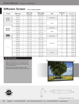 Procolor DIFFUSION SCREEN Le manuel du propriétaire
-
BIXOLON BCD-1000/1100 Guide d'installation
-
Trane Horizon OANE360A Installation, Operation and Maintenance Manual
-
Eaton DG1-357D6FB-C21C Communications Manual
-
 Ncr Rsd Atlanta Orderman9 WiFi WiFi Handheld Device Manuel utilisateur
-
Compaq 9G Le manuel du propriétaire
-
Denon DN-HC4500 Manuel utilisateur
-
-
AOpen AP5TC Manuel utilisateur

