
Veritas
®
Mk.II Power Sharpening System
INS-216-02 Rev. G
U.S. Patent No. 6,676,495
Mk.II Power Sharpening
System

ii
Veritas
®
Mk.II Power Sharpening System
Limited Warranty
Veritas
®
Tools Inc. warrants the Veritas
®
Mk.II Power Sharpening System against faulty
materials or workmanship for a period of fi ve years from date of purchase, less the electrical
components (including the motor and all wiring), which are warranted for a period of two
years from date of purchase. This warranty does not apply to wearing parts such as abrasives
and V-belt. During the warranty period, the defective product will be repaired or replaced
without charge or, at our option, the purchase price will be refunded. This warranty does
not cover damage caused by misuse or ordinary wear.
This warranty gives you specifi c legal rights, and you may have other rights, which vary
from one jurisdiction to another.
CANADA: 1090 Morrison Drive, Ottawa, ON K2H 1C2
USA: 814 Proctor Avenue, Ogdensburg, NY 13669-2205
customerser[email protected]
www.veritastools.com
© Veritas Tools Inc. 2009

iii
Table of Contents
Chapter 1: Introduction ................................................................................................. 1
Safety Rules ..........................................................................................................................2
Table 1: Minimum Gauge for Extension Cord..........................................................2
Requirements ........................................................................................................................3
Grounding Instructions .............................................................................................3
Règles de sécurité .................................................................................................................5
Tableau 1 : Jauge nominale d’une rallonge. ..............................................................5
Exigences ..............................................................................................................................7
Consignes de mise à la terre ......................................................................................7
Chapter 2: Unpacking & Assembly ............................................................................... 9
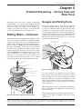
Chapter 3: General Principles – Straight-Edged Tools: Chisels and Planes ...............11
Quick Start .......................................................................................................................11
Tool Registration ................................................................................................................12
Abrasives ............................................................................................................................12
Micro-Bevels ......................................................................................................................12
Tool Holding .......................................................................................................................13
Standard Projection .................................................................................................13
Short Projection .....................................................................................................13
Skew Chisels ...........................................................................................................13
Chapter 4: Operation – Straight-Edged Tools:Chisels and Planes..............................15
How to Sharpen a New Tool ...............................................................................................15
Step 1: Lapping .......................................................................................................15
Step 2: Create the Primary Bevel ............................................................................16
Step 3: Create the Micro-Bevel ...............................................................................17
How to Resharpen a Tool ....................................................................................................17
How to Sharpen a Damaged Tool .......................................................................................17
Buffi ng/Honing ...................................................................................................................18
To Use .....................................................................................................................18
Convex Cutting Edge ..........................................................................................................18
Chapter 5: Freehand Sharpening – Carving Tools and Other Tools ...........................19
Buffi ng Wheel – Horizontal................................................................................................19
Gouges and Parting Tools ...................................................................................................19
Other Tools .........................................................................................................................20
Table of Contents

iv
Veritas
®
Mk.II Power Sharpening System
Chapter 6: Care and Maintenance ..............................................................................21
Lubrication .........................................................................................................................21
Abrasives ............................................................................................................................21
Spare Parts ..........................................................................................................................21
V-Belt ..................................................................................................................................21
To replace the belt ...................................................................................................21
Sound and Vibration Damping ...........................................................................................22
Chapter 7: Troubleshooting ..........................................................................................23
Sharpening on the Platter ....................................................................................................23
Micro-Bevel and Primary Bevel Not Parallel .........................................................23
Micro-Bevel on the Heel Instead of the Edge ........................................................23
Excessive Heat Build-Up .......................................................................................23
Edge Not Square Across Tool ................................................................................24
Incomplete Micro-Bevel .........................................................................................25
Motor Troubleshooting .......................................................................................................25
Drive Train ..............................................................................................................25
V-Belt Tension Adjustment .....................................................................................25
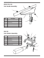
Appendix A: Exploded Assemblies & Master Parts List ..............................................26
Parts #3 & #4 Tool Guide Assembly ..................................................................................28
Part #5 Tool Holder Assembly ............................................................................................28
Appendix B: Optional & Accessory Parts ....................................................................29
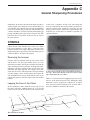
Appendix C: General Sharpening Procedures ............................................................31
CHISELS ...........................................................................................................................31
Removing the Lacquer ............................................................................................31
Lapping the Face of the Chisel ...............................................................................31
Shaping the Edge ....................................................................................................32
When to Resharpen? ...............................................................................................33
Buffi ng or Stropping Chisels ..................................................................................34
Utility Bevel-Edge Chisels .................................................................................................34
Paring Chisels .....................................................................................................................35
Mortise and Firmer Chisels ................................................................................................35
Skew Chisels .......................................................................................................................36
Corner Chisels ....................................................................................................................36
Japanese Chisels .................................................................................................................37
PLANES .............................................................................................................................38
Tuning a Plane ....................................................................................................................38
Sharpening the Blade of a Plane .........................................................................................40
Choosing a Bevel Angle ..........................................................................................40
Bench Planes ......................................................................................................................40
Smoothing Planes (#3, #4½, #5½) .....................................................................................41
Scrub Plane .........................................................................................................................41
Jack Planes, Jointer Planes and Others (#5, #6, #7 and #8) ...............................................41

v
Table of Contents
Block Planes .......................................................................................................................41
Bevel Angles ..........................................................................................................42
Low-Angle Block Planes ........................................................................................43
KNIVES..............................................................................................................................43
Sharpening Kitchen Knives ................................................................................................43
Bevel Angles ...........................................................................................................44
Using a Belt Sander ................................................................................................44
Using Stones ...........................................................................................................45
Marking Knives ..................................................................................................................45
Drawknives .........................................................................................................................45
Carver’s Drawknife .................................................................................................45
CARVING TOOLS.............................................................................................................46
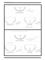
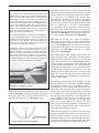
Sharpening Gouges .............................................................................................................46
Choosing a Bevel Angle ..........................................................................................46
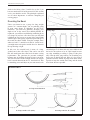
Rounding the Bevel .................................................................................................50
Gouge Tips – Fingernail, Square End or Swept Forward? .....................................51
Truing the Sweep ....................................................................................................51
Honing a Gouge ......................................................................................................52
Bent Gouges .......................................................................................................................53
Back-Bent Gouges ..................................................................................................54
Veining Tools ......................................................................................................................54
Parting Tools .......................................................................................................................54
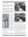
Shaping the Heel .....................................................................................................54
Wing Sweep ............................................................................................................55
Sharpening Parting Tools ........................................................................................56
Inshaves ..............................................................................................................................56
Scorps .................................................................................................................................57
Micro-Scorps ...........................................................................................................57
Hook Knives .......................................................................................................................57
Keeping Carving Tools Sharp .............................................................................................58
Index ............................................................................................................................59

vi
Veritas
®
Mk.II Power Sharpening System

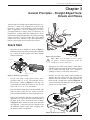
1
Introduction
The Veritas
®
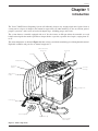
Mk.II Power Sharpening System will effi ciently sharpen any straight-edged chisel, plane blade or
carving tool to a degree of sharpness that cannot be surpassed by any other method. It is also an excellent general-
purpose system for a wide variety of tools with shaped edges, including gouges and V-tools.
The system features a turntable equipped with an 8" disc that rotates at 650 rpm. Above the turntable are a tool
holder and tool guide that make it possible to sharpen blades at specifi c, repeatable bevel angles, ranging from 15°
to 45°.
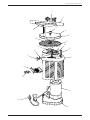
The main components are shown in Figure 1 (below) to help you with the terminology used throughout this manual.
Exploded assemblies and parts list are shown in Appendix A.
Chapter 1
Introduction
Figure 1: Main components.
Platter Retention
Thumbscrew
Turntable
Abrasive Discs (4)
4mm thick
Platter
3mm thick
Platter
Hex Keys (2)
Bevel Gauge
Registration Jig
Power Cord with
On/Off Switch
Locking Screw
Tool Guide
Assembly
Tool Holder

2
Veritas
®
Mk.II Power Sharpening System
WARNING: For your own safety, read the
instructions manual before operating the
Veritas
®
Mk.II Power Sharpening System.
Safety Rules
These safety instructions are provided to ensure safe use
of the Veritas
®
Mk.II Power Sharpening System. To ensure
your own safety, read these before you begin to use this
product and always follow these safety instructions.
1. Learn the tool’s applications and limitations as well
as the specific hazards related to the tool.
2. Use common sense. If an action appears to be
unsafe, it likely is. DON’T OVERREACH. Keep
proper footing and balance at all times.
3. Use correct power supply. Never use a power
source for which this tool was not designed. It
could cause serious injury. This tool is equipped
with a three-prong plug; it should be plugged into
a three-hole electric receptacle. An adapter should
be properly grounded (see Grounding Instructions,
page 3).
4. REDUCE THE RISK OF UNINTENTIONAL
STARTING. Make sure switch is in off position
before plugging in. USE PROPER EXTENSION
CORD. Make sure your extension cord is in good
condition. When using an extension cord, be sure
to use one heavy enough to carry the current your
product will draw. An undersized cord will cause a
drop in line voltage, resulting in loss of power and
overheating. Table 1 shows the correct size to use,
depending on cord length and nameplate ampere
rating. If in doubt, use the next heavier gauge. The
smaller the gauge number, the heavier the cord.
5. Wear proper eye protection. Everyday eyeglasses
have only impact-resistant lenses; they are not
safety glasses. Also use a face or dust mask if the
grinding operation is dusty. Visitors should wear
the same protection.
6. KEEP CHILDREN AWAY. All visitors should
be kept a safe distance from work area. MAKE
WORKSHOP KID PROOF with padlocks, master
switches, or by removing starter keys.
7. Wear proper apparel. Avoid wearing loose clothing,
gloves, ties, rings and bracelets, as these can get
caught in moving parts.
8. Long hair should be tied back and secured.
9. Do not work under the influence of drugs, alcohol, or
medication. Drugs, alcohol, medication and lack of
sleep cause impaired judgment and coordination and
should not be combined with power tool operation.
10. Use in an appropriate environment. Power tools
should be used only in dry, clean and well-lit
environments. Exposure to rain or use in the
presence of flammable liquids or gases could result
in damage or injury. Don’t use power tools in damp
or wet locations, or expose them to rain.
11. Keep power cord away from heat, oil and sharp edges.
12. Remove adjusting keys and wrenches before use.
Form habit of checking to see that keys and
adjusting wrenches are removed from tool before
turning it on.
13. Keep hands away from moving parts until they
have come to a complete stop and the power has
been disconnected.
14. Keep workplace clean. Cluttered work areas invite
accidents.
Table 1: Minimum Gauge for Extension Cord.
Ampere Rating
Volts Total length of cord in feet
120 V 25 ft 50 ft 100 ft 150 ft
More Than
Not More
Than AWG
0 6 18 16 16 14
6 10 18161412
10 12 16 16 14 12
12 16 14 12 Not Recommended

3
Introduction
15. Do not use the sharpening system if it is damaged.
A tool that does not operate correctly is a safety
hazard and should be fixed before further use. A
part that is damaged should be carefully checked to
determine that it will operate properly and perform
its intended function – check for alignment of
moving parts, binding of moving parts, breakage of
parts, mounting, and any other conditions that may
affect its operation.
16. Always disconnect the tool from the power source
when installing an accessory, adjusting the drive
belt or any other part. NEVER LEAVE TOOL
RUNNING UNATTENDED. TURN POWER OFF.
17. Refer to the Care and Maintenance section of this
manual for repairs and service details. Use only
identical replacement parts.
18. Do not alter or misuse the tool. Stop any operation
immediately if you notice anything abnormal.
19. Handle blades with care. This product will allow
the user to sharpen blades to a far greater degree
than is otherwise commonly possible.
20. Support workpiece with the tool guide and
sharpening system on the work surface. Never
lower the tool guide assembly so that it contacts
a rotating disc. Make sure the workpiece is not
in contact with the turntable before the power is
turned on. Wait until the sharpening system attains
full speed before proceeding.
21. Make sure the blade does not contact the platter
retention thumbscrew while the sharpening system
is turned on.
22. When the sharpening system is not in use, store it in
a dry area, elevated and out of the reach of children.
23. Do not yank the power cord to disconnect from
receptacle. Instead, use the molded plug to remove
the cord from receptacle.
24. The sharpening system should be used on a flat and
stable surface.
25. Do not operate in gaseous or explosive or other
environments with loose combustible substances
(e.g., wood dust). Sparks from sharpening may cause
fumes, dust or other materials to ignite. If you are
using a Shop-Vac
®
or other vacuum for abrasive dust
collection, remove any combustible material from it
(e.g., wood dust and chips) before sharpening.
26. Never attempt a leading cut with a buffing/honing
disc. Always use a trailing cut so that the disc
rotates away from the edge.
27. Never adjust the tool guide when the system is
running.
28. DON’T FORCE TOOL. It will do the job better
and safer at the rate for which it was designed.
29. USE RIGHT TOOL. Don’t force tool or attachment
to do a job for which it was not designed.
30. USE RECOMMENDED ACCESSORIES. Consult
the owner’s manual for recommended accessories.
The use of improper accessories may cause risk of
injury to persons.
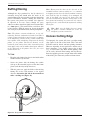
31. Grinding creates heat. Do not touch the ground
portion of the workpiece until you are sure that the
workpiece has cooled.
32. Always pay attention to the position of a blade in
relation to all parts of your body. Orient the tool
in relation to the direction of the moving abrasive
so that its edge will not point toward you should
you ever lose your grip on it. Try to visualize (or
predict) where the workpiece will go if control is
lost, and keep out of the way.
Requirements
There are some basic requirements for the operation of
your Power Sharpening System:
• Power: the cord must be plugged into a 120-volt
grounded outlet on a 15 amp circuit.
Grounding Instructions
1. All grounded, cord-connected tools:
In the event of a malfunction or breakdown,
grounding provides a path of least resistance
for electric current to reduce the risk of electric
shock. This tool is equipped with an electric cord
having an equipment-grounding conductor and a
grounding plug. The plug must be plugged into
a matching outlet that is properly installed and
grounded in accordance with all local codes and
ordinances. Do not modify the plug provided
– if it will not fit the outlet, have the proper
outlet installed by a qualified electrician. Improper
connection of the equipment-grounding conductor
can result in a risk of electric shock. The conductor
with insulation having an outer surface that is green

4
Veritas
®
Mk.II Power Sharpening System
with or without yellow stripes is the equipment-
grounding conductor. If repair or replacement
of the electric cord or plug is necessary, do not
connect the equipment-grounding conductor to a
live terminal. Check with a qualified electrician
or service personnel if the grounding instructions
are not completely understood, or if in doubt as to
whether the tool is properly grounded. Use only
three-wire extension cords that have three-prong
grounding plugs and three-pole receptacles that
accept the tool’s plug. Repair or replace damaged
or worn cord immediately.
2. Grounded, cord-connected tools intended for
use on a supply circuit having a nominal rating
less than 150 volts:
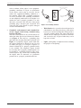
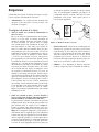
This tool is intended for use on a circuit that has an
outlet that looks like the one illustrated in Sketch
A in Figure 2. The tool has a grounding plug
that looks like the plug illustrated in Sketch A in
Figure 2. A temporary adapter, which looks like
the adapter illustrated in Sketch B, may be used
to connect this plug to a two-pole receptacle as
shown in Sketch B if a properly grounded outlet
is not available. The temporary adapter should
be used only until a properly grounded outlet can
be installed by a qualified electrician. The green-
colored rigid ear, lug, and the like, extending from
the adapter must be connected to a permanent
ground such as a properly grounded outlet box.
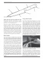
• Work Surface: the system has been designed to be
comfortable to use when placed on a work surface
between 30" and 36" from the floor. This provides a
38" to 44" working height. The same work surface
should also have ample space around it so that tools
and accessories may be placed where they can be
kept close at hand.
• Light: good lighting is important when evaluating
the progress of sharpening.
Figure 2: Grounding methods.
Grounding Pin
Cover of Grounded
Outlet Box
(A)
(B)
Metal
Screw
Temporary
Adapter

5
Introduction
AVERTISSEMENT : Pour votre propre
sécurité, lisez le guide d’utilisation avant de
faire fonctionner le système d’affûtage électrique
Mk.II Veritas
®
.
Règles de sécurité
Les présentes consignes de sécurité visent à faire en sorte
que le système d’affûtage électrique Mk.II Veritas
®
soit
utilisé de façon sécuritaire. Pour votre propre sécurité,
veuillez les lire avant de commencer à utiliser le produit
et respectez-les en tout temps.
1. Apprendre les domaines d’utilisation et les limitations
de l’outil, de même que les dangers connexes.
2. Faire preuve de bon sens. Toute action qui semble
être dangereuse l’est probablement. NE PAS
TENDRE LE BRAS TROP LOIN. Toujours avoir
une bonne prise de pied et un bon équilibre.
3. Utiliser la bonne source d’alimentation. Ne jamais
utiliser une source pour laquelle l’outil n’a pas été
conçu. On pourrait alors se blesser sérieusement.
L’outil est muni d’une fiche à trois broches; celle-ci
doit être branchée dans une prise à trois trous. Tout
adaptateur doit être mis à la terre de façon appropriée
(voir Consignes de mise à la terre, à la page 7).
4. RÉDUIRE LE RISQUE DE MISE EN MARCHE
INVOLONTAIRE. S’assurer que l’interrupteur est
à la position d’arrêt avant de brancher l’appareil.
UTILISER UNE RALLONGE APPROPRIÉE.
S’assurer que la rallonge est en bon état. Lorsqu’on
utilise une rallonge, s’assurer que le calibre des
conducteurs permet d’acheminer le courant appelé
par le produit. Une rallonge sous dimensionnée fera
chuter la tension de secteur, ce qui entraînera une
perte de puissance et fera surchauffer le système.
Le tableau 1 illustre le bon calibre à utiliser, selon
la longueur de la rallonge et l’intensité nominale
indiquée sur la plaque signalétique. En cas de
doute, utiliser une rallonge du calibre supérieur.
Plus le numéro de jauge est petit, plus le calibre des
conducteurs est élevé.
5. Porter la protection des yeux appropriée. Les
lunettes qu’on porte tous les jours sont seulement
munies de verres résistants aux chocs; ce ne sont
pas des lunettes de sécurité. Utiliser également un
masque facial ou antipoussières lorsqu’on procède
à un affûtage qui dégage de la poussière. Les
visiteurs doivent porter la même protection.
6. TENIR LES ENFANTS À DISTANCE. Tous
les visiteurs doivent être gardés à une distance
sécuritaire de la zone de travail. RENDRE
L’ATELIER À L’ÉPREUVE DES ENFANTS en
posant des cadenas et des interrupteurs principaux
ou en retirant les clés des démarreurs.
7. Porter des vêtements appropriés. Éviter de porter
des vêtements amples, des gants, une cravate, des
bagues ou des bracelets, car ils peuvent se prendre
dans les pièces mobiles.
8. Les cheveux longs doivent être attachés derrière la
tête et fixés en place.
9. Ne pas travailler sous l’effet d’une drogue, de
l’alcool ou d’un médicament. La consommation de
ces produits et le manque de sommeil entraînent une
diminution du sens critique et de la coordination,
et sont incompatibles avec l’utilisation d’un outil
électrique.
10. Utiliser le système dans un environnement
approprié. Les outils électriques ne doivent être
utilisés que dans un environnement sec, propre et
bien éclairé. L’exposition à la pluie ou l’utilisation
en présence d’un liquide ou d’un gaz inflammable
risque de causer des dommages ou des blessures.
Éviter de se servir d’un outil électrique dans un
endroit humide ou de l’exposer à la pluie.
11. Garder le cordon d’alimentation loin de la chaleur,
de l’huile et des arêtes tranchantes.
Tableau 1 : Jauge nominale d’une rallonge.
Ampérage
Volt Longueur totale de la rallonge (pieds)
120 V 25 50 100 150
Plus de Pas plus de AWG
0 6 18 16 16 14
6 10 18161412
10 12 16 16 14 12
12 16 14 12 non recommandé

6
Veritas
®
Mk.II Power Sharpening System
12. Enlever les clés et les dispositifs de réglage avant
d’utiliser le système. Prendre l’habitude de vérifier
si les clés et les dispositifs de réglage ont été enlevés
de l’outil avant de mettre celui ci en marche.
13. Garder les mains loin des pièces mobiles jusqu’à ce
que celles-ci se soient complètement immobilisées
et que le cordon d’alimentation ait été débranché.
14. Garder le lieu de travail propre. Les zones de travail
encombrées sont souvent la cause d’accidents.
15. Ne pas utiliser un système d’affûtage endommagé.
Un outil qui ne fonctionne pas correctement constitue
un risque d’accident et il faut le réparer avant de
s’en servir. Il faut vérifier soigneusement toute pièce
endommagée et déterminer si elle fonctionnera
correctement et remplira la fonction prévue – vérifier
si les pièces mobiles sont bien alignées et si des
pièces sont coincées ou brisées; vérifier le montage
et toute autre condition susceptible d’avoir une
incidence sur le fonctionnement du système.
16. Toujours déconnecter l’outil de la source
d’alimentation lorsqu’on pose un accessoire ou
qu’on règle la courroie d’entraînement ou toute
autre pièce. NE JAMAIS LAISSER L’OUTIL EN
MARCHE SANS SURVEILLANCE. COUPER
L’ALIMENTATION.
17. Se reporter à la section Soin et entretien du présent
guide d’utilisation pour trouver des détails au sujet
de la réparation ou de l’entretien courant. Utiliser
uniquement des pièces de rechange identiques.
18. Ne pas modifier ou mal employer l’outil. Cesser
toute opération immédiatement lorsqu’on remarque
quelque chose d’anormal.
19. Manipuler les lames avec soin. Le produit permet
d’affûter des lames de manière à les rendre
beaucoup plus aiguisées qu’il ne serait possible de
le faire autrement.
20. Supporter la pièce à travailler avec le guide de
l’outil et le système d’affûtage sur la surface de
travail. Ne jamais abaisser l’ensemble de guidage
de l’outil de manière à ce qu’il entre en contact
avec un disque tournant. S’assurer que la pièce à
travailler n’est pas en contact avec le disque rotatif
avant de mettre l’appareil sous tension. Attendre
que le système d’affûtage ait atteint le plein régime
avant de poursuivre.
21. S’assurer que la lame n’entre pas en contact avec
la molette de retenue du plateau lorsqu’on met le
système d’affûtage en marche.
22. Lorsqu’il n’est pas utilisé, ranger le système
d’affûtage dans un endroit sec, élevé et hors de
portée des enfants.
23. Ne pas tirer sur le cordon d’alimentation pour
le débrancher de la prise. Utiliser plutôt la fiche
moulée pour débrancher le cordon.
24. Utiliser le système d’affûtage sur une surface plane
et stable.
25. Ne pas utiliser le système dans un environnement
gazeux ou explosif, ou dans tout autre environnement
qui contient des matières combustibles (de la
poussière de bois, par exemple) à l’état libre. Les
étincelles produites par l’affûtage risqueraient alors
de causer l’inflammation des vapeurs, de la poussière
ou d’autres matériaux. En cas d’utilisation d’un
aspirateur Shop-Vac
®
ou de tout autre aspirateur
pour la collecte de la poussière d’abrasif, enlever
les matières combustibles qu’il contient (poussière
et copeaux de bois, par exemple) avant l’affûtage.
26. Ne jamais essayer de faire une coupe en attaque
avec une meule à polir. Toujours utiliser une
coupe en fuite, de sorte que l’abrasif s’éloigne du
tranchant lorsque le disque tourne.
27. Ne jamais régler le guide de l’outil pendant que le
système est en marche.
28. NE PAS TROP EXIGER DE L’OUTIL. Il fera
un meilleur travail, de façon plus sécuritaire, s’il
fonctionne à la capacité pour laquelle il a été
conçu.
29. UTILISER LE BON OUTIL. Éviter de forcer
l’outil ou le dispositif additionnel à faire un travail
pour lequel il n’a pas été conçu.
30. UTILISER LES ACCESSOIRES
RECOMMANDÉS. Consulter le manuel
du propriétaire pour trouver les accessoires
recommandés. L’utilisation d’accessoires
inappropriés risque de causer des blessures.
31. L’affûtage dégage de la chaleur. Ne pas toucher à
la partie meulée de la pièce à travailler tant qu’on
n’est pas certain que cette dernière a refroidi.
32. Toujours faire attention à la position de la lame par
rapport à toutes les parties du corps. Orienter l’outil
par rapport à la direction de l’abrasif en mouvement
de manière à éviter que le tranchant pointe vers soi,
au cas où l’on perdrait la prise de l’outil. Essayer
de visualiser (ou de prévoir) l’endroit où la pièce à
travailler serait projetée en cas de perte de maîtrise,
et s’écarter.

7
Introduction
Exigences
L’utilisation du système d’affûtage électrique est régie
par les exigences fondamentales suivantes :
• Alimentation – Le cordon doit être branché dans
une prise à 120 volts mise à la terre et reliée à un
circuit de 15 ampères.
Consignes de mise à la terre
1. Tous les outils avec cordon d’alimentation et
mise à la terre :
En cas de défaut de fonctionnement ou de panne,
la mise à la terre offre au courant électrique un
chemin de moindre résistance qui réduit le risque
de choc électrique. Le présent outil est équipé
d’un cordon muni d’un conducteur de mise à la
terre du matériel et d’une fiche avec broche de
masse. La fiche doit être branchée dans une prise
correspondante qui a été posée et mise à la terre en
conformité avec toutes les ordonnances et tous les
codes locaux. Éviter de modifier la fiche fournie
– si elle n’est pas adaptée à la prise, faire poser la
prise appropriée par un électricien qualifié. Quand
le conducteur de mise à la terre du matériel est mal
connecté, il y a risque de choc électrique. Il s’agit
du conducteur isolé dont le revêtement de couleur
verte peut être muni de bandes jaunes. Si la fiche
ou le cordon doit être réparé ou remplacé, éviter
de raccorder le conducteur de mise à la terre du
matériel à une borne sous tension. Vérifier auprès
d’un électricien qualifié ou du personnel d’entretien
quand les consignes de mise à la terre ne sont pas
bien comprises ou en cas de doute quant à savoir si
l’outil est bien mis à la terre. Utiliser uniquement
une rallonge à trois conducteurs munis d’une fiche
à trois broches et une prise tripolaire dans laquelle
il est possible de brancher la fiche de l’outil.
Réparer ou remplacer immédiatement tout cordon
endommagé ou usé.
2. Outil avec cordon et mise à la terre, destiné à
être raccordé à un circuit d’alimentation dont la
tension nominale est inférieure à 150 volts :
Le présent outil est destiné à être utilisé sur un circuit
comportant une prise de courant qui ressemble à la
prise illustrée dans le croquis A de la figure 2.
L’outil est équipé d’une fiche bipolaire avec terre
qui ressemble à celle illustrée dans le croquis A de la
figure 2. Un adaptateur temporaire, qui ressemble à
celui illustré dans le croquis B, peut servir à brancher
la fiche dans une prise bipolaire de la façon illustrée
dans le croquis B, quand il n’y a aucune prise mise à
la terre de façon appropriée. L’adaptateur temporaire
ne doit être utilisé que jusqu’à ce qu’une prise mise
à la terre de façon appropriée puisse être posée par
un électricien qualifié. L’oreille ou l’œil de couleur
verte, ou tout dispositif semblable, qui dépasse de
l’adaptateur doit être raccordé à une mise à la terre
permanente, telle qu’une boîte à prises mise à la
terre de façon appropriée.
• Surface de travail – En raison de sa conception, on
doit placer le système sur une surface qui se trouve
à une distance de 30 à 36 po du sol de manière à
être bien à l’aise pendant qu’on l’utilise. On obtient
ainsi une hauteur de travail de 38 à 44 po. Il faut
également que l’espace autour de la surface de
travail soit bien dégagé pour qu’on puisse placer les
outils et les accessoires à portée de la main.
• Lumière – Il est important de disposer d’un bon
éclairage lorsqu’on évalue l’évolution de l’affûtage.
Figure 2 : Méthode de mise à la terre.
Fiche avec broche de masse
Couvercle de la prise
mise à la terre
(A)
Vis à
métaux
Adaptateur
temporaire
(B)

8
Veritas
®
Mk.II Power Sharpening System

9
Unpacking & Assembly
• Remove the main unit from the box.
• Refer to Appendix A: Exploded Assemblies & Master
Parts List to check that you have all the components.
• Remove all packing materials.
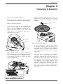
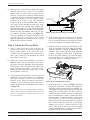
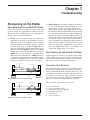
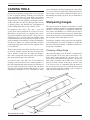
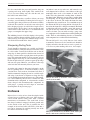
• Set the V-belt. Loosen the three motor mount
screws using the 4mm hex key. Pull the motor
pulley as shown in Figure 3 to tension the belt.
Tighten the motor mount screws. The V-belt
doesn’t need to be any tighter than you can
comfortably set by hand.
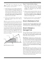
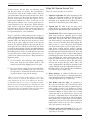
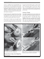
• Check that the pulleys are aligned horizontally.
Place a straight edge across the top surfaces of the
turntable and motor pulleys (see Figure 4). If they
are not aligned, loosen the set screw in the motor
pulley and align them.
• Install the turntable using the two
1
/4-20 ×
1
/2"
button-head cap screws. Ensure that the mating
surfaces are clean before mounting the turntable
(Figure 5).
• A clean environment is essential when applying
the abrasive. Wipe the platter first with a clean
rag dampened with methyl hydrate, methanol,
methylated spirits or isopropyl alcohol. (Mineral
spirits is not recommended as it can leave a slightly
oily residue.)
• Take note that the two platters are different
thicknesses. One is 3mm thick and the other is
4mm thick. Apply the 80x and 100µ (micron) on
opposite sides of the 4mm platter, 40µ and 9µ on
the 3mm platter. Peel the backing off the abrasive
disc. Handling it by the edges, align the center
holes and carefully press down from the center
outward. A rolling pin or sufficiently large dowel
helps. If any bubbles remain after rolling, pierce
them with a sharp point and press them down to
remove the air.
Chapter 2
Unpacking & Assembly
Figure 3: Tensioning the V-belt.
Figure 5: Installing the turntable.
Figure 4: Checking pulley alignment.
Motor Mount
Screw
V-Belt
Motor Mount
Screw
Motor Pulley
1
/4-20 ×
1
/2" Button-Head
Cap Screws
Turntable
Motor Pulley
Straight Edge
Turntable Pulley
Motor Pulley Set
Screw Location
Cross section
showing motor
pulley set screw.

10
Veritas
®
Mk.II Power Sharpening System
• Using the
1
/8" ball-end hex key provided, loosely
install the tool guide rod onto the tool guide yoke
with the two 10-24 ×
1
/2" button-head cap screws
(Figure 6).
• Insert the tool guide assembly into the tool guide
bore in the chassis (Figure 7).
• Tighten the locking screw.
• The tool guide rod must be aligned parallel to the
turntable. Put the thicker of the two platters in place
on the turntable; secure it with the platter retention
thumbscrew. To allow the tool guide assembly to
be adjusted, loosen the locking screw and push the
tool guide assembly all the way down so that the
tool guide yoke comes to rest on the base and only
the 15° mark is visible on the tool guide scale. With
one hand, keep the tool guide rod in contact with
the abrasive disc while tightening the screws. With
your hand off the tool guide rod, check by eye that
it remains absolutely parallel to the platter. If not,
repeat this alignment procedure.
Figure 7: Installation of the tool guide assembly.
Figure 6: Tool guide assembly.
10-24 ×
1
/2" Button-Head
Cap Screws
Tool Guide Rod
Tool Guide Yoke
Locking Screw
Tool Guide
Bore
Tool Guide
Assembly

11
General Principles – Straight-Edged Tools: Chisels and Planes
Any tool with a fl at straight-edged cutting blade up to 2
1
/2"
wide and
1
/2" thick can be sharpened to any bevel angle
between 15° and 45° on the sharpening system’s turntable.
Refer to Appendix C: General Sharpening Procedures
(excerpted from The Complete Guide To Sharpening by
Leonard Lee, available from The Taunton Press) for an
explanation of sharpening principles. If you prefer to jump
right in and learn as you go, reading Quick Start should
enable you to do so. Otherwise, for a full explanation of
how the system works, proceed to Tool Registration.
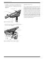
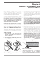
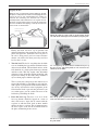
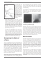
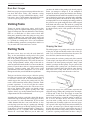
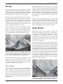
Quick Start
• Set up the tool to be sharpened as shown in Figure 8.
Extend the cutting edge of the tool using the registration
jig as shown to ensure it projects the correct amount
from the tool holder.
• Set the tool guide to the desired bevel angle,
anywhere from 15° to 45°. The included Veritas
®
Bevel Gauge (shown in Figure 1) will help you
to determine the initial bevel angle of any of your
tools, from 15° to 45° in 5° increments.
• Place the thicker (4mm) platter on the turntable with
either the 80x or 100µ face up, secure it with the
platter retention thumbscrew, and turn the power on.
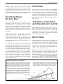
• Engage the tool holder with the tool guide rod and
apply the bevel edge of the blade to the turntable at
the right of the center. Position the tool as shown
in Figure 9 while moving the blade back and forth
and applying a consistent pressure downward on
the turntable. Check results often, stopping once
the primary bevel is established.
Note: Make sure the blade does not contact
the platter retention thumbscrew while the
sharpening system is turned on.
• Turn power off, switch to the thinner (3mm) platter
with the 9µ abrasive facing up and repeat the previous
step. It should take only about 1 to 3 seconds of
grinding to achieve a satisfactory micro-bevel.
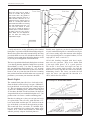
• Remove the wire edge formed when grinding by
applying the back of the blade flat against the 9µ
abrasive while the turntable is rotating. Position the
blade to make a leading cut as shown in Figure 10. If
you feel uncomfortable doing this, turn the power off
and do so as if using a stone.
Chapter 3
General Principles – Straight-Edged Tools:
Chisels and Planes
Figure 8: Setting tool projection.
Figure 9: Tool position.
Figure 10: Wire edge removal.
Registration Jig
Tool Holder

12
Veritas
®
Mk.II Power Sharpening System
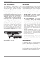
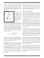
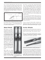
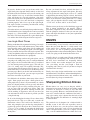
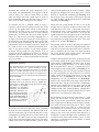
Tool Registration
The system relies on the tool holder to be used
with the tool registration jig and the tool guide to
grind and hone accurate, repeatable bevel angles.
As illustrated in Figure 8, the blade should always
project the same distance from the holder, with
the exception of especially short tools (see Short
Projection). Different bevel angles are achieved
solely by varying the height of the tool guide. The
tool guide post has a series of indents that engage a
ball plunger installed in the base. This creates seven
pre-determined settings for the tool guide height as
shown on the tool guide scale (from 15° to 45° in
5° increments). As the post is moved up and down,
it will register at each 5° setting with a small click.
The corresponding bevel angle is read according to
the lowest number that can be read from the scale
as shown in Figure 11. The guide may be set to
any height between the two extremes; however, if
the angle required is not one of the presets, you will
need to mark the position with a fine-tip marker on
the label, or with a scratch or other mark on the post
itself, for the setting to be repeatable. If unusual
bevel angles are required more often than the seven
presets, you can back off the ball plunger to eliminate
the standard presets by first removing the locking
screw (to access the ball plunger).
Abrasives
The types and grades of abrasives used with the system
have been carefully selected for fast material removal
and cool grinding temperatures. As with all sharpening
methods, the sharpening system uses a range of
abrasives from very coarse to very fi ne. Each grade is
suitable for a specifi c stage of the sharpening process.
Four different grades are included with each system for
use on the turntable. They are as follows:
• 80x (180µ) zirconia – applied to one side of the
thick (4mm) platter, and used for basic shaping of
the bevel and grinding out edge damage.
• 100µ (150x) aluminum oxide (1µ = 1 micron
=
1
/1,000,000 metre) – applied to other side of the
thick (4mm) platter. The micron grade refers to
the average particle size. This abrasive is the
first to be used if the blade was last sharpened on
the system at the same angle and no large nicks
or chips are to be removed from the edge. This
abrasive must also be used if a blade was started
with the 80x platter because, as with all abrasive
action, when progressing from coarse to fine, one
should not make too large a jump from one grade
to the next.
• 40µ (320x) aluminum oxide – applied to one side
of the thin (3mm) platter. This grade is used only
for lapping the face of a chisel or plane blade.
In normal sharpening (i.e., when working on the
bevel), this abrasive is not used.
• 9µ (1200x) aluminum oxide – applied to the
other side of the thin (3mm) platter. This abrasive
is used to create the micro-bevel with the final
cutting edge.
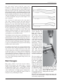
Micro-Bevels
As explained in Appendix C: General Sharpening
Procedures, concentrating one’s honing efforts on a
micro-bevel will save a great deal of time and abrasive.
When using this system, a very slight change of angle is
automatically created when the user switches from the
coarse abrasive discs mounted on the thick platter to the
fi ne abrasive discs mounted on the thin platter. The user
needs to do nothing more than switch to the platter with
the fi ne abrasive to achieve a micro-bevel of about 1°.
Figure 11: Setting the bevel angle.
Locking Screw
Read angle here.

13
General Principles – Straight-Edged Tools: Chisels and Planes
Tool Holding
Standard Projection
Use of the tool holder at the standard projection is covered
in Chapter 4, Step 2: Create the Primary Bevel.
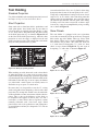
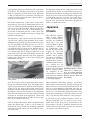
Short Projection
Some tools such as short butt chisels, spokeshaves and
small palm planes have blades that are too short to
register properly at standard projection. Blades as short
as 1
1
/2" may still be sharpened using the short setting
of the blade projection jig. As shown in Figure 12 and
on the label of the blade projection jig, when the short
projection is used, the angle as displayed on the tool
guide is no longer correct. The conversion can be made
using the table pictured on the jig label.
When working on wide, short tools, such as butt chisels
or spokeshave blades, it is often easier to ensure square
registration using the existing edge against the registration
jig rather than the side of the blade and the shoulder of the
tool holder. If the dull edge is out of square, the human
eye (aided with a small square) can usually correct to
obtain the set-up as square as it needs to be.
Be aware that it is not possible to use the 15° setting
on the tool guide when sharpening a chisel at the short
projection. To attempt this would cause the underside
of the tool holder to come into contact with the abrasive
platter. This is due to the thickness of the blade to
be sharpened and applies to chisels only. It is not a
restriction, as short chisels (butt or Japanese) cannot
normally withstand such a low bevel angle. Small
plane blades such as for spokeshaves and palm planes
are much thinner and may be sharpened at 15° with no
interference.
As noted on the Blade Projection Jig Label, when using
short projection do not set the tool guide to 40° or 45°.
Using such a combination of settings will create a bevel
angle of 52° or 59° which, aside from being unusable
cutting angles for woodworking, may cause the tool to
jam between the turntable and tool guide when taking
a leading cut. If for some reason such an obtuse angle
is necessary, it may be accomplished by using a trailing
cut as shown in Figure 21.
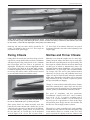
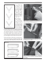
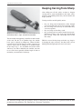
Skew Chisels
The tool holder is equipped with two registration
screws that are normally stored out of the way in tapped
holes on the top of the holder. These are for use with
skew chisels. When used as shown in Figure 13, they
will allow the user to hone a 60° point (30° skew) on
a
1
/2" wide chisel. If sharpening a
3
/4" wide, 30° skew
chisel, set up as shown in Figure 14. Use one screw if
sharpening a 1" wide skew as shown in Figure 15.
Figure 13:
1
/2" skew chisel.
Figure 15: 1" skew chisel.
Figure 14:
3
/4" skew chisel.
! = DO NOT USE
(SEE MANUAL)
!
!
Figure 12: Blade projection jig label.
Contact
Contact
Contact

14
Veritas
®
Mk.II Power Sharpening System
La page est en cours de chargement...
La page est en cours de chargement...
La page est en cours de chargement...
La page est en cours de chargement...
La page est en cours de chargement...
La page est en cours de chargement...
La page est en cours de chargement...
La page est en cours de chargement...
La page est en cours de chargement...
La page est en cours de chargement...
La page est en cours de chargement...
La page est en cours de chargement...
La page est en cours de chargement...
La page est en cours de chargement...
La page est en cours de chargement...
La page est en cours de chargement...
La page est en cours de chargement...
La page est en cours de chargement...
La page est en cours de chargement...
La page est en cours de chargement...
La page est en cours de chargement...
La page est en cours de chargement...
La page est en cours de chargement...
La page est en cours de chargement...
La page est en cours de chargement...
La page est en cours de chargement...
La page est en cours de chargement...
La page est en cours de chargement...
La page est en cours de chargement...
La page est en cours de chargement...
La page est en cours de chargement...
La page est en cours de chargement...
La page est en cours de chargement...
La page est en cours de chargement...
La page est en cours de chargement...
La page est en cours de chargement...
La page est en cours de chargement...
La page est en cours de chargement...
La page est en cours de chargement...
La page est en cours de chargement...
La page est en cours de chargement...
La page est en cours de chargement...
La page est en cours de chargement...
La page est en cours de chargement...
La page est en cours de chargement...
La page est en cours de chargement...
La page est en cours de chargement...
La page est en cours de chargement...
La page est en cours de chargement...
La page est en cours de chargement...
-
 1
1
-
 2
2
-
 3
3
-
 4
4
-
 5
5
-
 6
6
-
 7
7
-
 8
8
-
 9
9
-
 10
10
-
 11
11
-
 12
12
-
 13
13
-
 14
14
-
 15
15
-
 16
16
-
 17
17
-
 18
18
-
 19
19
-
 20
20
-
 21
21
-
 22
22
-
 23
23
-
 24
24
-
 25
25
-
 26
26
-
 27
27
-
 28
28
-
 29
29
-
 30
30
-
 31
31
-
 32
32
-
 33
33
-
 34
34
-
 35
35
-
 36
36
-
 37
37
-
 38
38
-
 39
39
-
 40
40
-
 41
41
-
 42
42
-
 43
43
-
 44
44
-
 45
45
-
 46
46
-
 47
47
-
 48
48
-
 49
49
-
 50
50
-
 51
51
-
 52
52
-
 53
53
-
 54
54
-
 55
55
-
 56
56
-
 57
57
-
 58
58
-
 59
59
-
 60
60
-
 61
61
-
 62
62
-
 63
63
-
 64
64
-
 65
65
-
 66
66
-
 67
67
-
 68
68
-
 69
69
-
 70
70


dans d''autres langues
- English: VERITAS Mk.II User manual
Autres documents
-
Delta 14-651 Manuel utilisateur
-
 Oregon Scientific Mini Grinder Manuel utilisateur
-
Delta 14-651 Le manuel du propriétaire
-
PROPOINT 8680944 Le manuel du propriétaire
-
 Drill Doctor XP Manuel utilisateur
-
 Drill Doctor XP2 Manuel utilisateur
-
Draper Drill Grinding Attachment Mode d'emploi
-
Drill Doctor 350x Manuel utilisateur
-
Drill Doctor 750X Manuel utilisateur
-
Dremel 6700-01 Mode d'emploi


