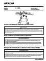
Hitachi C 10FL Instruction Manual And Safety Instructions
- Catégorie
- Outils électroportatifs
- Taper
- Instruction Manual And Safety Instructions

ADVERTENCIA
¡La utilización inapropiada e insegura de esta herramienta eléctrica puede resultar en lesiones
serias o en la muerte!
Este manual contiene información importante sobre la seguridad del producto. Lea y comprenda
este manual antes de utiIizar la herramienta eléctrica. Guarde este manual para que puedan
leerlo otras personas antes de que utilicen la herramienta eléctrica.
MANUAL DE INSTRUCCIONES E INSTRUCCIONES DE SEGURIDAD
AVERTISSEMENT
Une utilisation incorrecte et dangereuse de cet outil motorisé peut entraîner la mort ou de
sérieuses blessures corporelles!
Ce mode d’emploi contient d’importantes informations à propos de la sécurité de ce produit.
Prière de lire et d’assimiler ce mode d’emploi avant d’utiliser l’outil motorisé. Garder ce mode
d’emploi à la disponibilité des autres utilisateurs avant qu’ils utilisent I'outil motorisé.
MODE D'EMPLOI ET INSTRUCTIONS DE SECURITE
WARNING
Improper and unsafe use of this power tool can result in death or serious bodily injury!
This manual contains important information about product safety. Please read and understand
this manual before operating the power tool. Please keep this manual available for others before
they use the power tool.
INSTRUCTION MANUAL AND SAFETY INSTRUCTIONS
C 10FL
Model Stationary Table Saw
Modèle Scie sur table
Modelo Sierra de mesa fija

— 2 —
TABLE DES MATIERES
Français
SECTION PAGE
Spécifications produit ...........................................................27
Consignes de sécurité relatives aux outils électriques ......28
Consignes de sécurité relatives à la scie sur table .............29
Exigences électriques et sécurité .........................................30
Accessoires ............................................................................31
Outils nécessaires pour le montage ....................................31
Contenu de l’emballage ........................................................32
SECTION PAGE
Connaitre votre scie sur table stationnaire .........................34
Glossaire des termes ............................................................35
Montage et réglages .............................................................36
Utilisation ...............................................................................43
Entretien .................................................................................47
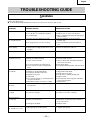
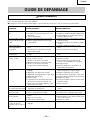
Guide de dépannage .............................................................49
Liste des pièces .....................................................................76
SECCIÓNPÁGINA
Conozca su sierra de mesa fija ............................................58
Glosario se términos .............................................................59
Montaje y ajustes ..................................................................60
Funcionamiento ....................................................................67
Mantenimiento ......................................................................71
Guía de solución de problemas ...........................................73
Lista de piezas .......................................................................76
ÍNDICE
Español
SECCIÓNPÁGINA
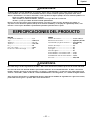
Especificaciones del producto .............................................51
Seguridad de la herramienta eléctrica ................................52
Seguridad de la sierra de mesa ...........................................53
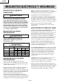
Requisitos eléctricos y seguridad ........................................54
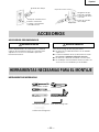
Accesorios .............................................................................55
Herramientas necesarias para el montaje ..........................55
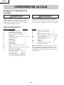
Contenido de la caja .............................................................56
HITACHI AUTHORIZED SERVICE CENTERS
Service under this warranty is available from Hitachi Koki U.S.A., Ltd. at :
IN THE U.S.A.
3950 Steve Reynolds Blvd. Norcross, GA 30093
9409 Owensmouth Ave. Chatsworth, CA 91311
OR CALL: (800) 546-1666 for a service center nearest you.
IN CANADA
6395 Kestrel Road Mississauga, ON L5T 1Z5
OR CALL: (800) 970-2299 for a service center nearest you.
CENTRES TECHNIQUES HITACHI AGREES
La réparation est réalisée dans le cadre de cette garantie par Hitachi Koki U.S.A., Ltd. :
AUX ETATS-UNIS
3950 Steve Reynolds Blvd. Norcross, GA 30093
9409 Owensmouth Ave. Chatsworth, CA 91311
OU APPELEZ LE: (800) 546-1666 pour connaître le centre
technique le plus proche de chez vous.
AU CANADA
6395 Kestrel Road Mississauga, ON L5T 1Z5
OU APPELEZ LE: (800) 970-2299 pour connaître le centre
technique le plus proche de chez vous.
CENTROS DE SERVICIO AUTORIZADOS DE HITACHI
Hitachi Koki U.S.A. Ltd. proporciona un servicio de reparaciones bajo esta garantía en:
EN EE.UU.
3950 Steve Reynolds Blvd. Norcross, GA 30093
9409 Owensmouth Ave. Chatsworth, CA 91311
O LLAME AL: (800) 546-1666 para informarse del centro de
reparaciones más cercano.
EN CANADA
6395 Kestrel Road Mississauga, ON L5T 1Z5
O LLAME AL: (800) 970-2299 para informarse del centro de
reparaciones más cercano.
SECTION PAGE
Know Your Stationaly Table Saw ........................................10
Glossary of terms ..................................................................11
Assembly and Adjustments .................................................12
Operation ...............................................................................19
Maintenance ..........................................................................23
Troubleshooting Guide .........................................................25
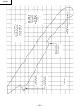
Push Stick Pattern .................................................................26
Parts List ................................................................................76
CONTENTS
English
SECTION PAGE
Product Specifications ............................................................3
Power Tool Safety ...................................................................4
Table Saw Safety ....................................................................5
Electrical Requirements and Safety ...................................... 6
Accessories and Attachments ............................................... 7
Tools Needed For Assembly ..................................................7
Carton Contents ..................................................................... 8

— 3 —
English
WARNING
Some dust created by power sanding, sawing, grinding, drilling and other construction activities contains chemicals
known to the state of California to cause cancer, birth defects or other reproductive harm. Some examples of these
chemicals are:
• Lead from lead-based paints
• Crystalline silica from bricks, cement and other masonry products
• Arsenic and chromium from chemically treated lumber
Your risk from these exposures varies, depending on how often you do this type of work. To reduce your exposure to
these chemicals, work in a well-ventilated area and work with approved safety equipment such as dust masks that are
specially designed to filter out microscopic particles.
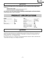
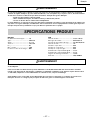
PRODUCT SPECIFICATIONS
SAW
Table Size ....................................... 27-1/8” x 20-1/8”
Table Extensions ........................... Left & Right
Extension Fence Capacity ............. 24” Left & Right
Blade Size....................................... 10”
Rip Scale ........................................ YES
Rip Fence........................................ YES
Miter Gauge ................................... YES
Maximum Cut Depth @ 90°.......... 3-3/8”
Maximum Cut Depth @ 45°.......... 2-1/4”
Maximum Dado Cut Width ........... 13/16”
Net Weight ..................................... 264.5 LBS
WARNING
To avoid electrical hazards, fire hazards or damage to the table saw, use proper circuit protection.
This table saw is wired at the factory for 110-120/220-240 Volt operation. It must be connected to a 110-120 Volt / 15
Ampere or 220-240 Volt / 7.5 Ampere time delay fuse or circuit breaker. To avoid shock or fire, replace power cord
immediately if it is worn, cut or damaged in any way.
Before using your table saw, it is critical that you read and understand these safety rules. Failure to follow these rules
could result in serious injury to you or damage to the table saw.
MOTOR
HP (Maximum developed) ............ 3.0
Type ................................................ Induction
Amps .............................................. 15 / 7.5
Voltage ........................................... 120 / 240
Hz .................................................... 60
RPM (no load) ................................ 3450
Overload Protection ...................... YES

— 4 —
English
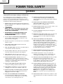
POWER TOOL SAFETY
WARNING
Before using your table saw, it is critical that you read and understand these safety rules. Failure to follow these rules
could result in serious injury or damage to the table saw.
Good safety practices are a combination of common
sense, staying alert and understanding how to use your
power tool. To avoid mistakes that could cause serious
injury, do not plug in your power tool until you have read
and understood the following safety rules:
1. READ and become familiar with this entire Operator’s
Manual. LEARN the tool’s applications, limitations and
possible hazards.
2.
WARNING
Look for this symbol that identifies important safety
precautions. It means CAUTION! BECOME ALERT!
YOUR SAFETY IS INVOLVED!
3. NEVER OPERATE THIS MACHINE WITHOUT THE
SAFETY GUARD IN PLACE FOR ALL THROUGH
SAWING OPERATIONS.
4. DO NOT USE IN A DANGEROUS ENVIRONMENT
such as damp or wet locations or exposure to rain.
Keep work area well lighted.
5. DO NOT use power tools in the presence of flammable
liquids or gases.
6. KEEP WORK AREA CLEAN. Cluttered areas and
benches invite accidents.
7. KEEP CHILDREN AWAY. All visitors should be kept at
a safe distance from the work area.
8. DO NOT FORCE THE TOOL. It will do the job better
and safer at the rate for which it was designed.
9. USE THE RIGHT TOOL. Don’t force the tool or
attachment to do a job for which it is not designed.
10. WEAR PROPER APPAREL. DO NOT wear loose
clothing, gloves, neckties, rings, bracelets or other
jewelry that may get caught in moving parts. Non-slip
footwear is recommended. Wear protective hair
covering to contain long hair.
11. WEAR A FACE MASK OR DUST MASK. Sawing,
cutting and sanding operations produce dust.
12. DISCONNECT TOOLS before servicing and when
changing accessories such as blades, cutters, etc.
13. REDUCE THE RISK OF UNINTENTIONAL STARTING.
Make sure the switch is in the OFF position before
plugging into the power supply.
14. USE ONLY RECOMMENDED ACCESSORIES.
Consult the Operator’s Manual for recommended
accessories. The use of improper accessories may
cause injury to you or damage to the tool.
15. REMOVE ADJUSTING KEYS AND WRENCHES.
Form the habit of checking to see that keys and
adjusting wrenches are removed from the tool before
turning ON.
16. NEVER LEAVE TOOL RUNNING UNATTENDED.
TURN THE POWER “OFF”. Do not leave the tool
before it comes to a complete stop.
17. NEVER STAND ON TOOL. Serious injury could occur if
the tool is tipped or if the cutting tool is
unintentionally contacted.
18. DO NOT OVERREACH. Keep proper footing and
balance at all times.
19. MAINTAIN TOOLS WITH CARE. Keep tools sharp and
clean for most efficient and safest performance.
Follow instructions for lubricating and changing
accessories.
20. CHECK FOR DAMAGED OR LOOSE PARTS.
Before further use of the tool, a guard or other part
that is damaged should be carefully checked to ensure
it will operate properly and perform its intended
function. Check for alignment of moving parts, loose
binding of moving parts, mounting and any other
conditions that may affect its safe operation. A guard
or other part that is loose or damaged should be
properly adjusted repaired or replaced.
21. MAKE WORKSHOP CHILD PROOF with padlocks,
master switches or by removing starter keys.
22. DO NOT operate the tool if you are under the
influence of any drugs, alcohol or medication that
could impair your ability to use the tool safely.
23. USE DUST COLLECTION SYSTEM wherever possible.
Dust generated from certain materials can be
hazardous to your health and in some cases, a fire
hazard. Always operate the power tool in a well-
ventilated area with adequate dust removal.
24. ALWAYS WEAR EYE PROTECTION. Any power tool
can throw foreign objects into your eyes that could
cause permanent eye damage. ALWAYS wear safety
goggles (not glasses) that comply with ANSI safety
standard Z87.1. Everyday glasses have only impact
resistant lenses. They ARE NOT safety glasses.
NOTE: Glasses or goggles not in compliance with
ANSI Z87.1 could cause serious injury when they
break.
25. DIRECTION OF FEED. Feed work into a blade or cutter
against the direction of rotation of the blade or cutter
only.

— 5 —
English
TABLE SAW SAFETY
1. ALWAYS USE SAW BLADE GUARD, splitter and anti-
kickback pawls for every operation for which they can
be used, including through sawing. Through sawing
operations are those in which the blade cuts
completely through the workpiece when ripping or
crosscutting.
2. ALWAYS HOLD WORK FIRMLY against the miter
gauge or rip fence.
3. USE A PUSH STICK when required. Always use a
push stick especially when ripping narrow stock. Refer
to ripping instructions in this Operator’s Manual
where the push stick is covered in detail. A pattern for
making your own push stick is included on page 26.
4. NEVER PERFORM ANY OPERATION “FREE HAND”,
which means using only your hands to support or
guide the workpiece. Always use either the fence or
the miter gauge to position and guide the work.
WARNING: FREEHAND CUTTING IS THE MAJOR
CAUSE OF KICK-BACK & FINGER/HAND
AMPUTATIONS.
5. NEVER STAND or have any part of your body in line
with the path of the saw blade. Keep your hands out
of the saw blade path.
6. NEVER REACH behind or over the cutting tool for any
reason.
7. REMOVE the rip fence when crosscutting.
8. DO NOT USE a molding head with this saw.
9. FEED WORK INTO THE BLADE against the direction of
rotation only.
10. NEVER use the rip fence as a cut-off gauge when
crosscutting.
11. NEVER ATTEMPT TO FREE A STALLED SAW BLADE
without first turning the saw OFF. Turn power switch
OFF immediately to prevent motor damage.
12. PROVIDE ADEQUATE SUPPORT to the rear and the
sides of the saw table for long or wide workpieces.
13. AVOID KICKBACKS (work thrown back towards you)
by keeping the blade sharp, the rip fence parallel to
the saw blade and by keeping the splitter, anti-
kickback pawls and guards in place, aligned and
functioning. Do not release work before it has passed
all the way past the saw blade. Do not rip work that is
twisted, warped or does not have a straight edge to
guide it along the fence.
14. AVOID AWKWARD OPERATIONS and hand positions
where a sudden slip could cause your hand to move
into the saw blade.
15. NEVER USE SOLVENTS to clean plastic parts.
Solvents could possibly dissolve or otherwise damage
the material. Only a soft damp cloth should be used to
clean plastic parts.
16. MOUNT your table saw on a bench or stand before
performing any cutting operations. Refer to
ASSEMBLY AND ADJUSTMENTS on page 12.
17. NEVER CUT METALS or materials which may make
hazardous dust.
18. ALWAYS USE IN WELL-VENTILATED AREA.
Remove sawdust frequently. Clean out sawdust from
the interior of the saw to prevent a potential fire
hazard. Attach a vacuum to the dust port for
additional sawdust removal.
19. NEVER LEAVE THE SAW running unattended. Do not
leave the saw until it comes to a complete stop.
20. For proper operation follow the instructions in this
Operator’s Manual entitled ASSEMBLY AND
ADJUSTMENTS (Page 12). Failure to provide sawdust
fall-through and removal hole will allow sawdust to
build up in the motor area resulting in a fire hazard
and potential motor damage.

— 6 —
English
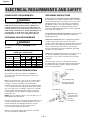
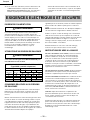
ELECTRICAL REQUIREMENTS AND SAFETY
POWER SUPPLY REQUIREMENTS
WARNING
To avoid electrical hazards, fire hazards or damage to the
table saw, use proper circuit protection. Always use a
separate electrical circuit for your tools. This power tool
is wired at the factory for 120V operation. Connect it to a
120V, 15 Amp circuit and use a 15 Amp time delay fuse or
circuit breaker. To avoid shock or fire, replace the cord
immediately if it is worn, cut or damaged in any way.
EXTENSION CORD REQUIREMENTS
WARNING
Any extension cord must be GROUNDED for safe
operation.
MINIMUM GAUGE FOR EXTENSION CORDS
(AWG type / 120 Volt only)
Ampere Rating Total length in feet
Not
25’ 50’ 100’ 150’
More Than More Than
AWG
0 6 18 16 16 14
6 10 18161412
10 12 16 16 14 12
12 16 14 12 Not Applicable
GUIDELINES FOR EXTENSION CORDS
Any extension cord used for power tools MUST be
grounded (3-wire with two flat prongs and one round
ground prong).
Make sure the extension cord is in good condition. When
using an extension cord, make sure you use one heavy
enough to carry the current the tool will draw. An
undersized cord will cause a drop in line voltage resulting
in loss of power and overheating. The table above shows
the correct size to use according to extension cord length
and nameplate ampere rating. If in doubt, use the next
heavier gauge cord. The smaller the gauge number the
heavier the cord.
NOTE: The 12 to 16 Amp rating is correct for this tool. It is
highlighted in the table above.
Be sure your extension cord is properly wired and in good
condition. Always replace a damaged extension cord or
have it repaired by a qualified person before using it.
Protect your extension cords from sharp objects,
excessive heat and damp or wet areas.
Before connecting the saw to the extension cord, make
sure the saw switch is turned OFF.
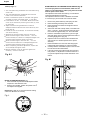
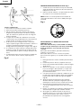
GROUNDING INSTRUCTIONS
IN THE EVENT OF A MALFUNCTION OR BREAKDOWN,
grounding provides a path of least resistance for electric
current and reduces the risk of electric shock. This saw is
equipped with an electric cord that has an equipment
grounding conductor and a grounding plug. The plug
MUST be plugged into a matching receptacle that is
properly installed and grounded in accordance with ALL
local codes and ordinances.
DO NOT MODIFY THE PLUG PROVIDED. If it will not fit the
receptacle, have the proper receptacle installed by a
qualified electrician.
IMPROPER CONNECTION of the equipment grounding
conductor can result in risk of electric shock. The
conductor (wire) with the green insulation (with or without
yellow stripes) is the equipment grounding conductor. If
repair or replacement of the electric cord or plug is
necessary, DO NOT connect the equipment grounding
conductor to a live terminal.
CHECK with a qualified electrician or service personnel if
you do not completely understand the grounding
instructions, or if you are not sure the saw is properly
grounded.
Use only 3-wire extension cords that have 3-prong
grounding plugs and 3-pole grounding receptacles that
accept the saw’s plug. Repair or replace damaged or
worn cords immediately.
3-Prong Plug
Grounding Prong
Properly Grounded
3-Prong Receptacle
2-Prong
Receptacle
Adapter
Grounding Lug
Make Sure This
is Connected to a
Known Ground

— 7 —
English
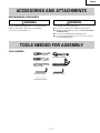
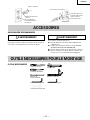
ACCESSORIES AND ATTACHMENTS
RECOMMENDED ACCESSORIES
WARNING
Visit your Hardware Department or see the Power and
Hand Tools Catalog to purchase recommended
accessories for this power tool.
TOOLS NEEDED FOR ASSEMBLY
TOOLS NEEDED
Medium screwdriver
#2 Philips screwdriver
Straight edge
Adjustable wrench
Combination square
4mm Hex wrench
17mm Hex wrench
5mm Hex wrench
WARNING
To avoid the risk of personal injury:
䢇 Do not use a dado with a diameter larger than 8”.
䢇 Maximum dado width is 13/16”. DO NOT USE WIDER
COMBINATIONS.
䢇 Do not use molding head set with this saw.
䢇 Do not modify this power tool or use accessories not
recommended by Store.

— 8 —
English
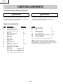
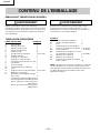
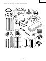
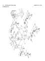
TABLE OF LOOSE PARTS
ITEM DESCRIPTION QUANTITY
A. Table saw assembly 1
B. Table extension wing 2
C. Rear table extension rail 2
D. Front table extension rail 2
E. Rail cover 6
F. Blade guard and splitter 1 each
G. Adhesive washer 3
H. Rip fence 1
I. Miter gauge 1
J. Dust chute 1
K. Blade wrench 1
L. Push stick 1
M. Dodo table insert 1
N. Blade 1
O. Handwheel handle & nuts 1 each
P. Handwheel and handle 1
Q Table extension hardware
Square nut 6
Hex hd. bolt M8x1.25-16 2
Hex hd. bolt M8x1.25-20 4
Hex.socket hd.cap bolt M8x1.25-16 6
Hex hd. bolt & washer M10x1.5-25 6
STAND
V. Top leg bracket 1
W. Bottom leg bracket 1
X. Leg 4
Y. Leg front bracket 1
Z. R & L leg bracket 1 each
AA. Foot and hardware 1 set
BB. Storage bracket & foot hardware 1 set
CC. Caster assemblies A 2
DD. Caster assemblies B 2
EE. Stand & caster mounting hardware 36
NOTE: To make assembly easier, keep contents of box
together. Apply a coat of automobile wax to the table.
Wipe all parts thoroughly with a clean dry cloth. This will
reduce friction when pushing the workpiece.
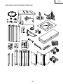
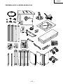
CARTON CONTENTS
UNPACKING AND CHECKING CONTENTS
WARNING
Separate all parts from packing materials. Check each part
with the illustration on the next page and the “Table of
Loose Parts” to make certain all items are accounted for,
before discarding any packing material.
WARNING
If any part is missing or damaged, do not attempt to
assemble the table saw, plug in the power cord, or turn
the switch ON until the missing or damaged part is
obtained and is installed correctly.

— — 9
UNPACKING YOUR STATIONARY TABLE SAW
A
B
C
D
E
F
G
H
I
J
K
L
M
N
O
P
Q
VW X Y Z
AA
BB
CC
DD
EE
English

— 10
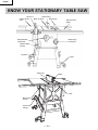
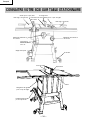
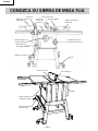
Miter Gauge
Blade Guard
Rip Fence
ON/OFF Switch
with key
Leg Stand
Table Extension
(Right)
Table Extension
(Left)
Blade Tilt Scale
Blade Tilting
Handwheel
Blade Elevation
Handwheel
Caster
Miter Gauge
Storage
Rip Fence
Storage
Splitter
Table Insert
Table
—
English
KNOW YOUR STATIONARY TABLE SAW

— 11 —
English
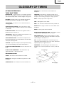
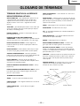
GLOSSARY OF TERMS
HITACHI PROFESSIONAL
TABLE SAW TERMS
MITER GAUGE – A guide used for crosscutting operations
that slides in the tabletop channels located on either side
of the blade. It helps make accurate straight or angle cuts.
RIP FENCE – A guide used for rip cutting that clamps to
the tabletop. It allows the workpiece to be straight.
TABLE INSERT – Provides access to the blade arbor for
changing blades.
OVERLOAD RESET SWITCH – Resets the thermocouple
and provides a way to restart the saw motor if it overheats
or overloads.
BLADE BEVEL SCALE – Measures the angle the blade is
tilted when set for a bevel cut.
TABLE SCALE – Measures the distance the rip fence is set
from the blade, allowing quick setups.
ANTI-KICKBACK PAWLS – Prevents the workpiece from
being kicked upward or back toward the front of the table
saw by the spinning blade.
SPLITTER – Keeps the workpiece spread apart after being
cut, to prevent binding on the blade and workpiece.
BLADE ELEVATION HANDWHEEL – Raises and lowers the
blade.
BLADE TILTING HANDWHEEL – Tilts the blade to any
angle between 0° to 45° for bevel cuts.
WOODWORKING TERMS
ARBOR – The shaft on which a blade is mounted.
BEVEL CUT – An angle cut made through the face of the
workpiece.
COMPOUND CUT – A simultaneous bevel and miter cut.
CROSSCUT – A cut made across the width of the
workpiece.
FREEHAND – Performing a cut without using a fence
(guide), hold down or other proper device to prevent the
workpiece from twisting during the cutting operation.
GUM – A sticky sap from wood products.
HEEL – Misalignment of the blade.
KERF – The amount of material removed by a blade cut.
MITER CUT – An angle cut made across the width of the
workpiece.
RESIN – A sticky sap that has hardened.
REVOLUTIONS PER MINUTE (RPM) – The number of turns
completed by a spinning object in one minute.
SAW BLADE PATH – The area of the workpiece or table
top directly in line with the travel of the blade or the part
of the workpiece that will be cut.
SET – The distance between two saw blade tips, bent
outward in opposite directions to each other. The further
apart the tips are, the greater the set.
WORKPIECE – The item being cut. The surfaces of a
workpiece are commonly referred to as faces, ends and
edges.
Leading Edge
Sawblada Path
Trailing Edge
Surface
Kerf
Workpiece

— — 12
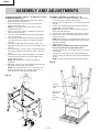
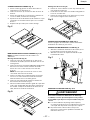
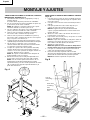
ASSEMBLY AND ADJUSTMENTS
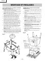
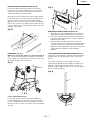
ASSEMBLE TABLE SAW TO STAND (Fig. A, B)
1. Place protective corrugated cardboard or old blanket
on floor to protect the saw table surface.
2. Place the saw up-side down on the protective material
(Fig. B).
3. Position the recessed-side dust chute and the stand
up-side down on the saw base.
NOTE: Make sure front of stand and front of saw are
facing the same direction.
4. Line up four holes in saw base, dust chute and stand.
5. Fasten saw to dust chute and stand using four bolts,
washers and nuts.
NOTE: Place washer on each bolt before inserting into
saw base and through the support. Nut must be flush
against the bracket.
6. Tighten all four nuts.
NOTE: Do not overtighten the locknuts mounting the
base to the stand (you may damage the base).
7. Carefully set the saw in its upright position on a clean
level surface.
8. Push down on the lever of right wheel assemblies to
unlock. Push up on the lever of right wheel assemblies
to lock.
NOTE: You will need assistance form another person.
Fig. B
Leg set
mounting
hole
Saw base
hole
Dust chute
mounting
hole
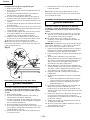
ASSEMBLE STAND (Fig. A)
1. Unpack all parts and group by type and size (Fig. A).
Refer to parts list for quantities.
2. Attach one support (4) to leg (1) using one square
neck bolt (2) and nut (3).
NOTE: Do not tighten bolts until stand is properly
aligned (see step # 7).
3. Attach other end of support to another leg using one
square neck bolt and nut.
4. Join front frame assemblies using support (5) square
neck bolts and nuts.
5. Join rear frame assemblies using short upper support
(6) and short bottom support (7), square neck bolts
and nuts.
6. Place three rubber feet (8) onto three leg and the
adjustable foot (9) and nut (10) onto the bracket of the
other leg.
7. Attach the hooks (11) and power cord storage (12) to
the frame as desired. The hooks are used to hold the
fence.
8. Place stand on level surface and adjust so all legs are
contacting the floor and are at similar angles to the
floor.Tighten all bolts.
NOTE: Stand should not rock after all bolts are
tightened.
9. Mounting a caster (13) on each leg by tightening three
bolts (14) and nuts (15). Four casters.
NOTE: Two casters marked "A" are used for the Front-
Right & Rear-Left legs, two casters marked "B" are
used for the Front-Left & Rear-Right legs.
Fig. A
1
6
1
1
4
4
12
8
14
15
5
3
3
3
9
10
3
2
7
11
13
1
ESTIMATED ASSEMBLY TIME 50~70 MINUTES (2 PEOPLE)
English

— — 13
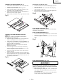
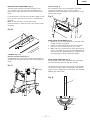
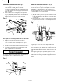
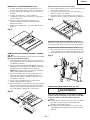
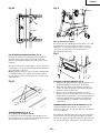
ASSEMBLY THE TABLE EXTENSION (Fig. C)
1. Place the left table extension next to the saw table,
aligning the mounting holes (1).
2. Place bolts (2) and thread in mounting holes.
3. Place a straight edge or combination square on the
saw table, across the table extension.
4. Adjust the mounting bolts (2) until the extension is
flush with the saw table. Tighten.
5. Repeat these procedures for the right extension table.
Fig. C
ASSEMBLY THE FRONT AND REAR TABLE RAIL
(Fig. D, E)
NOTE: Front of table rails assemblies are different.
Assembly the front rail (Fig. D)
1. Attach the right front side cover (1) into right front
table rail (2). Repeat for the left front rail.
2. Place the hex. bolts M8-20 (3), hex bolts M8-16 (4)
through the holes at the front table edge. Screw the
square nuts (5) onto each bolts.
NOTE: Keep the bolts and square nuts loosened
before front rail fixed.
3. Attach the right front rail onto proper location by
having the square nuts pass through the slot of the
front rail. Repeat for the left front rail.
4. Attach the middle plug (6) to connect the two half
front rail. (Fig. E)
5. When the blade was installed, use the rip fence and
gauge to adjust the front rail to proper location. When
the front rail is level with table, then fix the front rail
by tightening the six bolts.
Fig. D
1
2
3
4
4
5
6
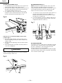
Assembly the rear table rail (Fig. E)
6. Attach the side covers (1) and middle plug (2) to the
rear table rails (3).
7. Place the rear table rails on the saw table, aligning
with the holes in each rail.
8. Place the bolts (4) and tread in the holes; tighten the
bolts and check the alignment again.
Fig. E
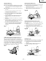
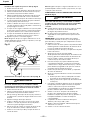
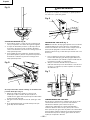
BLADE RAISING HANDWHEEL (Fig. F)
Thread the blade handwheel handle (1) into blade raising
handwheel (2) and tighten.
BLADE TILTING HANDWHEEL (Fig. F)
1. Attach the blade tilting handwheel (3) to the elevation
screw at the front of the saw.
2. Attach and tighten the dome nut (4) at the end of the
shaft.
Fig. F
1
2
4
3
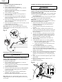
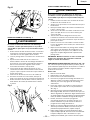
BLADE GUARD ASSEMBLY (Fig. G, H)
WARNING
To avoid injury from an accidental start, make sure the
switch is in the OFF position and the plug is disconnected
from the power source outlet.
When installing the blade guard, cover the blade teeth
with a piece of folded cardboard to protect yourself
from possible injury.
Never operate this machine without the safety guard
in place for all through sawing operations.
1
2
1
4
2
3
English

— — 14
Installing the blade guard assembly (Fig. G)
1. Remove the table insert.
2. Unlock the blade bevel lock knob (1).
3 With the blade evevation handwheel (2), raise the
blade to the maximum height.
4. Using the blade tilting handwheel, tilt the blade to
45 on the bevel scale.
5. Lock the blade tilt locking knob.
6. Locate the splitter assembly mounting bracket in
back of the blade.
7. Cover the blade teeth with a folded cardboard or
position the plastic blade guard over the blade to
protect your hands.
8. Place the two kickback pawls (5) toward the rear of the
table, and align the splitter mounting holes to the
holes in the bracket.
9. Place the steel flat washers (6) on the two bolts (7) and
tread the bolts into the holes.
10. Tighten the bolts with the angled wrench.
Note: Make sure the "anti-kick back pawls" do not get
caught between the insert and the guard, but rest on top
of the insert.
Fig. G
5
Removing the blade guard assembly (Fig. H)
WARNING
To avoid injury from an accidental start, make sure the
switch is in the OFF position and the plug is disconnected
from the power source outlet.
1. Remove the table insert.
2. With the blade elevation handwheel (1), raise the
blade to the maximum height.
3. Loosen blade lock handle (2) and move the handwheel
(1) to 45 on the bevel scale.
4. Tighten the bevel lock handle.
5. Cover the blade teeth with a piece of folded cardboard
or position the plastic blade guard over the blade to
protect your hands.
6. Loosen the knob (5) and remove the blade guard
assembly, then retighten the knob.
7. Return the blade to 90 and replace the table insert.
Note: Make sure the "anti-kick back pawls" do not get
caught between the insert and the guard, but rest on top
of the insert.
ALIGNING THE BLADE GUARD SPLITTER (Fig. H)
WARNING
To avoid injury from an accidental start, make sure the
switch is in the OFF position and the plug is disconnected
from the power source outlet.
When installing the blade guard, cover the blade teeth
with a piece of folded cardboard to protect yourself
from possible injury.
Never operate this machine without the safety guard
in place for all through sawing operations.
IMPORTANT: The splitter must always be correctly
aligned with the blade so the cut workpiece will pass on
either side without binding or twisting.
1. Remove the table insert and raise the blade to the
maximum height by turning the blade elevation
handwheel clockwise.
2. Lift the blade guard and position it toward the rear of
the table.
3. Adjust the blade to the 90 vertical position by
unlocking the blade tilting lock knob and turning the
bevel tilting handwheel counterclockwise, and then
lock into position.
4. To see if the blade (1) and splitter (2) are correctly
aligned, lay a combination square along the side of
the blade and against the splitter (making sure the
square is between the teeth of the blade).
5. Tilt the blade to the 45 position and check the
alignment again.
6 If the blade and splitter are not correctly aligned:
a. Remove the blade guard by removing the wing
bolt that locks the guard in place.
b. Loosen and remove the two bolts (3) from the
mounting bracket (7).
7. Place two adhesive washers (5) on the guard
mounting bracket (attached to the saw). Position
them over the corresponding mounting bolt holes
(refer to step 6-b) after removing the adhesive backing
affixed to the washers.
8. Replace the two guard mounting bolts (3) and tighten
securely. Also reattach the blade guard assembly,
affixing it to the machine by its corresponding wing
bolt.
9. Check the splitter and blade alignment again at both
90 and 45 .
10. Add or remove the adhesive washers until the
alignment is correct.
11. Replace the table insert.
Fig. H
1
2
7
5
2
3
1
2
6
7
English

— — 15
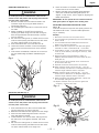
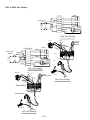
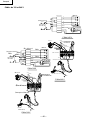
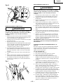
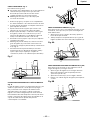
REMOVING THE BLADE (Fig. I)
WARNING
To avoid injury from an accidental start, make sure the
switch is in the OFF position and the plug is disconnected
from the power source outlet.
1. Remove the table insert and raise the blade to the
maximum height by turning the blade elevation
handwheel clockwise.
2. Lift the blade guard and position it toward the rear of
the table.
3. Adjust the blade to the 90 vertical position by
unlocking the blade tilting lock knob and turning the
bevel tilting handwheel counterclockwise, and then
lock into position.
4. Pull the motor locking lever (1) toward the front of the
machine while spinning the blade until the latch locks
into place and the blade will no longer turn.
5. Place the blade wrench (3) on the arbor nut (4).
6. Loosen and remove the arbor nut and the flange by
pulling the wrench toward the front of the machine
(5).
7. Then remove the blade (6). Clean but do not remove
the inner blade flange (5) before reassembling the
blade.
Fig. I
INSTALLING A BLADE (Fig. I)
WARNING
To avoid injury from an accidental start, make sure the
switch is in the OFF position and the plug is disconnected
from the power source outlet.
1. Place the blade onto the arbor with the blade teeth
pointing forward to the front of the saw.
2. Make sure the blade fits flush against the inner flange.
3. Clean the outer blade flange and install it onto the
arbor and against the blade.
4. Thread the arbor nut onto the arbor, making sure the
flat side of the nut is against the blade, then hand-
tighten.
5. Pull the motor locking lever (1) toward the front of the
machine while spinning the blade until the latch locks
into place and the blade will no longer turn.
6. Place the wrench on the arbor nut and turn clockwise
(toward the rear of the saw table).
7. Replace the table insert and blade guard assembly.
Verify that the blade and blade guard splitter are
aligned. If they are not, refer to page 14, Aligning The
Blade Guard Splitter.
IMPORTANT: Do not operate this saw until the blade and
blade guard splitter are aligned and in working order.
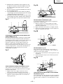
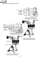
ADJUSTING THE 90 AND 45 POSITIVE STOPS
(Fig. J, K)
Your saw has positive stops that will quickly position the
saw blade at 90 and 45to the table. Make adjustments
necessary.
90 Stop
1
3
4
6
5
1. Disconnect the saw from the power source.
2. Turn the blade tilting handwheel until the blade tilting
scale is at 90.
3. Turn the blade elevation handwheel and raise the
blade to the maximum elevation.
4. Place a combination square on the table and against
the blade to check if the blade is 90to the table.
5. If the blade is not 90to the table. R emove the back
cover (2) of the base by removing the screw(1), three
for each side.
6. Adjust the bevel tilting handwheel to make an
adequate distance between the anchor block (3) and
bevel gear (4).
7. Loosen the two set screws(5) of the anchor block
(3) with 3mm allen key.
8. Separate the anchor block(3) from the worm(6).
When the bevel angle is more than 90, turn the
anchor block(3) to A direction in adequate degree until
the bevel angle and bevel scale is the same.
When the bevel angle is less than 90, tur n the
anchor block to B direction in adequate degree until
the bevel angle and bevel scale is the same.
9. When completing the above adjustment, replace the
set screws(5) and tighten them.
10. Replace the back cover (2) and then tighten the
screws(1), three for each side.
Fig. J
Fig. K
1
2
A
B
4
3
5
6
only if
English

— 16
Fig. K-1
BLADE TILTING INDICATOR (Fig. L)
1. When the blade is positioned at 90, adjust the blade
tilt pointer to read 0 on the scale.
2. Remove the magnifier, position the pointer over 0
and replace the magnifier.
NOTE: Make a trial cut on scrap wood before making
critical cuts. Measure for accuracy.
Fig. L
0
5
10
BLADE PARALLEL TO THE MITER GAUGE GROOVE (Fig. M)
To avoid injury from an accidental start, make sure the
switch is in the OFF position and the plug is disconnected
from the power source outlet.
This adjustment was made at the factory, but it should be
rechecked and adjusted if necessary.
This adjustment must be correct or kickback could result
in a serious injury and accurate cuts cannot be made.
1. Remove the yellow switch key and unplug the saw.
2. Raise the blade guard away from the blade.
3. Raise the blade to the maximum height and set the
belel angle at 0 .
4. Select and mark with a felt tip marker, one blade tooth
with a right set angle and position this tooth at the
front of the saw approximately 1/2 above the table.
5. Place the combination square base (1) into the right
side miter gauge groove (2) flush against the inside of
the miter gauge groove. (Fig. M)
6. Adjust the ruler so it touches the front marked tooth
and lock ruler so it holds its position in the square
assembly.
7. Rotate the blade to the rear of the saw bringing the
marked tooth approximately 1/2 above the blade.
8. Carefully slide the combination square to the rear until
the ruler touches the marked tooth.
9. If the ruler touches the marked tooth at the front and
rear position, no adjustment is needed at this time. If
not, perform adjustment procedure described in next
section.
Fig. M
1
2
45 Stop (Fig.K-1)
""
"
"
A
B
3
4
5
6
—
1. Turn the blade tilting handwheel until the blade tilting
scale is 45.
2. Turn the blade elevation handwheel and raise the
blade to the maximum elevation.
3. Place a combination square on the table and against
the blade to check if the blade is 45to the table.
4. If the blade is not 45to the table. R emove the back
cover (2) of the base by removing the screw(1), three
for each side.
5. Adjust the bevel tilting handwheel to make an
adequate distance between the anchor block (3) and
bevel gear (4).
6. Loosen the two set screws(5) of the anchor block(3)
with 3mm allen key.
7. Separate the anchor block(3) from the worm(6).
When the bevel angle is more than 45, turn the
anchor block(3) to A direction in adequate degree until
the bevel angle and bevel scale is the same.
When the bevel angle is less than 45, tur n the
anchor block to B direction in adequate degree until
the bevel angle and bevel scale is the same.
8. When completing the above adjustment, replace the
set screws(5) and tighten them.
9. Replace the back cover (2) and then tighten the
screws(1), three for each side.
English

— — 17
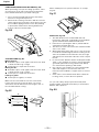
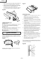
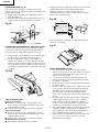
INSTALLING THE TABLE INSERT (Fig. N)
The table insert has been previously installed on your
unit. However, you must verify that the table insert is
flush with the table top surface on all four corners of the
insert.
If the table insert is not flush with the table, adjust the four
bolts (1) with a 4mm hex. wrench until it is parallel with
the table.
Note: To raise the insert, turn the hex screws
counterclockwise, to lower the insert, turn the hex screws
clockwise.
Fig. N
1
STORAGE (Fig. O, P)
Rip fence and miter gauge (Fig. O)
Storage brackets for the rip fence (2) and miter gauge (1)
are located on the right side of the saw housing and frame
of leg.
Fig. O
2
2
3
1
4
1
Power Cord (Fig. P)
For convenience and to prevent damage to the power
cord when the table saw is not in use or is being
transported, the frame of leg has two brackets (1) on the
side for cord atorage.
Fig. P
1
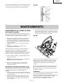
MITRE GAUGE ADJUSTMENT (Fig. Q)
1. Make sure that the mitre gauge bar (1) will slide freely
through the table top grooves.
2. Loosen the lock knob handle (2) and turn the gauge
body (3) to set the pointer (4) at 0 on the scale.
3. Make a 90 cut in a scrap piece of wood. Check the cut
to see if it is 90. If not, loosen the lock knob handle (2)
and move the mitre gauge body until it is square to the
miter gauge bar by using a combination square.
MITRE GAUGE OPERATION (Fig. Q)
The mitre gage is accurately construted with index stops
at 0 , 15 , 30 , 45 , 60 both right and left side.
The operate the mitre gage, simply loosen the lock handle
(2) and move the body of the mitre gauge to the desired
angle. The mitre gauge body will stop at 0 , 15 , 30 , 45 ,
60 both right and left side.
Fig. Q
English

— 18 —
English
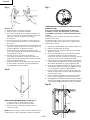
RIP FENCE ADJUSTMENT (Fig. R)
1. For adjustments, position the fence to the right of the
blade, parallel with the miter gauge groove.
2. Place the rear clamp (1) of the fence on the back rail of
the table, and lower the front end over the front rail
(2). Push the handle (3) down to lock.
3. To change the position of the fence, lift up on the
handle to unlock, and slide the fence to the desired
position, then push the handle down to lock.
Fig. R
2
3
If the fence is loose when the handle is in the locked
position: (Fig. S)
1. Move the handle upward to the unlocked position.
Turn the adjusting screw (4) clockwise until the rear
clamp is snug.
2. DO NOT turn the adjusting screw more than 1/4 turn
at a time.
3. Over-tightening the screw will cause the rip fence to
come out of alignment.
WARNING
Failure to properly align the fence can cause “kickback”
and serious injury could occur.
Fig. S
41
RIP FENCE INDICATOR (Fig. T)
NOTE: The rip fence indicator points to the scale on the
front of the table saw. Measurement shown by the
indicator will provide the user with accuracy up to 1/16 of
an inch. Measurement shown is the distance from the
blade to the side of the fence closest to the blade.
1. To check the accuracy, measure the actual distance to
the side of the rip fence. If there is a difference
between the measurement and the indicator, adjust
the indicator as shown next.
2. Loosen the indicator screws (1). Slide the indicator to
the correct measurement position on the scale, then
retighten the indicator screws (1).
Fig. T
11
2
RIP FENCE OPERATION
The rip fence moves to either side of saw blade. The right
side is the most common position. Front and rear guide
the fence. Calibrations on the front guide rail show
distance between fence and saw blade.
To adjust rip fence, raise clamp lever to maximun height,
push fence desired distance from saw blade, and turning
micro-set knob (2) left or right.

— 19 —
English
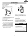
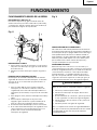
OPERATION
Fig. V
1
2
3
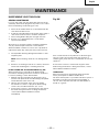
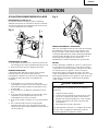
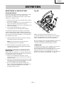
OVERLOAD PROTECTION
This saw has an overload relay button that resets the
motor after it shuts off due to overloading or low voltage.
If the motor stops during operation, turn the ON / OFF
switch to the OFF position. Wait about five minutes for the
motor to cool, push in on the reset button and turn the
switch to the ON position.
CUTTING OPERATIONS
There are two basic types of cuts: ripping and
crosscutting. Ripping is cutting along the length and the
grain of the workpiece. Crosscutting is cutting either
across the width or across the grain of the workpiece.
Neither ripping nor crosscutting may be done safely
freehand. Ripping requires the use of the rip fence, and
crosscutting requires the miter gauge.
WARNING
Before using the saw each and every time, check the
following:
1. The blade is tightened to the arbor.
2. The bevel angle lock knob is tight.
3. If ripping, the fence is locked into position & is parallel
to the miter gauge groove.
4. The blade guard is in place and working properly.
5. Safety glasses are being worn.
The failure to adhere to these common safety rules, and
those printed in the front of this manual, can greatly
increase the likelihood of injury.
BASIC SAW OPERATIONS
RAISE THE BLADE (Fig. U)
To raise or lower the blade, turn the blade elevation
handwheel (1) to the desired blade height, and then
tighten the bevel lock handle (2) to maintain the desired
blade angle.
Fig. U
1
2
3
TILTING THE BLADE
1. To tilt the saw blade for bevel cutting, loosen the lock
knob (2) and turn the tilting handwheel (3).
2. Tighten the lock knobs (2) to secure.
ON / OFF SWITCH (Fig. V)
The ON / OFF switch has a removal key. With the key
removed from the switch, unauthorized and hazardous
use by children and others is minimized.
1. To turn the saw ON, lift switch cover (1) and insert the
safety switch key (2) into the slot in the switch. Move
the switch (3) upward to the ON position.
2. To turn the saw OFF, move the switch downward.
3. To lock the switch in the OFF position, grasp the end
(or yellow part) of the safety switch key, and pull it
out.
4. With the safety switch key removed, the switch will
not operate.
5. If the safety switch key is removed while the saw is
running, it can be turned OFF but cannot be restarted
without inserting the safety switch key.

— 20 —
English
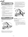
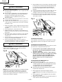
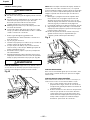
RIPPING (Fig. W, X)
WARNING
To prevent serious injury:
䢇 Never use a miter gauge when ripping.
䢇 Do not allow familiarity or frequent use of your table
saw to cause careless mistakes. Remember that even
a careless fraction of a second is enough to cause a
severe injury.
䢇 Keep both hands away from the blade and clear from
the path of the blade.
䢇 The workpiece must have a straight edge against the
fence and must not be warped, twisted, or bowed
when ripping.
1. Remove the miter gauge and store it in the “storage”
compartment in the base of the saw.
2. Secure the rip fence to the table.
3. Raise the blade so it is about 1/8” higher than the top
of the workpiece.
4. Place the workpiece flat on the table and against the
fence. Keep the workpiece away from the blade.
5. Turn the saw ON and wait for the blade to come to
full speed.
6. Slowly feed the workpiece into the blade by pushing
forward only on the workpiece section (1) that will
pass between the blade and the fence. (Fig. W)
WARNING
AVOID KICKBACK by pushing forward on the section of
the workpiece that passes between the blade and the
fence. Never perform any freehand operations.
Fig. W
1
NOTE: Always use a push stick. When width of the rip is
narrower than 2” the push stick cannot be used because
the guard will interfere…therefore, use the auxiliary fence
so the push stick can be used as shown on page 26.
7. Keep your thumbs off the table top. When both of
your thumbs touch the front edge of the table (2),
finish the cut with a push stick. To make an additional
push stick, use the pattern on page 26.
8. The push stick (3) should always be used. (Fig. X)
9. Continue pushing the workpiece with the push stick
(3) until it passes through the blade guard and clears
the rear of the table.
10. Never pull the piece back when the blade is turning.
Turn the switch OFF. When the blade completely
stops, you can then remove the workpiece.
Fig. X
1
3
2
BEVEL RIPPING
This cut is the same as ripping except the blade bevel
angle is set to an angle other than “0°”.
RIPPING SMALL PIECES
To avoid injury from the blade contact, never make cuts
narrower than 1/2” wide.
1. It is unsafe to rip small pieces. Instead, rip a larger
piece to obtain the size of the desired piece.
2. When a small width is to be ripped and your hand
cannot be safely press between the blade and the
rip fence, use one or more push sticks to move the
workpiece. Always use a push stick during ripping
operations.
La page est en cours de chargement...
La page est en cours de chargement...
La page est en cours de chargement...
La page est en cours de chargement...
La page est en cours de chargement...
La page est en cours de chargement...
La page est en cours de chargement...
La page est en cours de chargement...
La page est en cours de chargement...
La page est en cours de chargement...
La page est en cours de chargement...
La page est en cours de chargement...
La page est en cours de chargement...
La page est en cours de chargement...
La page est en cours de chargement...
La page est en cours de chargement...
La page est en cours de chargement...
La page est en cours de chargement...
La page est en cours de chargement...
La page est en cours de chargement...
La page est en cours de chargement...
La page est en cours de chargement...
La page est en cours de chargement...
La page est en cours de chargement...
La page est en cours de chargement...
La page est en cours de chargement...
La page est en cours de chargement...
La page est en cours de chargement...
La page est en cours de chargement...
La page est en cours de chargement...
La page est en cours de chargement...
La page est en cours de chargement...
La page est en cours de chargement...
La page est en cours de chargement...
La page est en cours de chargement...
La page est en cours de chargement...
La page est en cours de chargement...
La page est en cours de chargement...
La page est en cours de chargement...
La page est en cours de chargement...
La page est en cours de chargement...
La page est en cours de chargement...
La page est en cours de chargement...
La page est en cours de chargement...
La page est en cours de chargement...
La page est en cours de chargement...
La page est en cours de chargement...
La page est en cours de chargement...
La page est en cours de chargement...
La page est en cours de chargement...
La page est en cours de chargement...
La page est en cours de chargement...
La page est en cours de chargement...
La page est en cours de chargement...
La page est en cours de chargement...
La page est en cours de chargement...
La page est en cours de chargement...
La page est en cours de chargement...
La page est en cours de chargement...
La page est en cours de chargement...
-
 1
1
-
 2
2
-
 3
3
-
 4
4
-
 5
5
-
 6
6
-
 7
7
-
 8
8
-
 9
9
-
 10
10
-
 11
11
-
 12
12
-
 13
13
-
 14
14
-
 15
15
-
 16
16
-
 17
17
-
 18
18
-
 19
19
-
 20
20
-
 21
21
-
 22
22
-
 23
23
-
 24
24
-
 25
25
-
 26
26
-
 27
27
-
 28
28
-
 29
29
-
 30
30
-
 31
31
-
 32
32
-
 33
33
-
 34
34
-
 35
35
-
 36
36
-
 37
37
-
 38
38
-
 39
39
-
 40
40
-
 41
41
-
 42
42
-
 43
43
-
 44
44
-
 45
45
-
 46
46
-
 47
47
-
 48
48
-
 49
49
-
 50
50
-
 51
51
-
 52
52
-
 53
53
-
 54
54
-
 55
55
-
 56
56
-
 57
57
-
 58
58
-
 59
59
-
 60
60
-
 61
61
-
 62
62
-
 63
63
-
 64
64
-
 65
65
-
 66
66
-
 67
67
-
 68
68
-
 69
69
-
 70
70
-
 71
71
-
 72
72
-
 73
73
-
 74
74
-
 75
75
-
 76
76
-
 77
77
-
 78
78
-
 79
79
-
 80
80


Hitachi C 10FL Instruction Manual And Safety Instructions
- Catégorie
- Outils électroportatifs
- Taper
- Instruction Manual And Safety Instructions
dans d''autres langues
- English: Hitachi C 10FL
- español: Hitachi C 10FL
Documents connexes
-
Hitachi C10RB - 10" Professional Jobsite Table Saw Manuel utilisateur
-
-
-
-
-
-
Hitachi 10FCH2 Manuel utilisateur
-
-
-
Autres documents
-
Skil 1131 AA Manuel utilisateur
-
Rubi ND-7in READY 120V 60HZ Le manuel du propriétaire
-
Black & Decker 90528116 Manuel utilisateur
-
Delta 36-L31 Manuel utilisateur
-
Delta SHOPMASTER SM200L Manuel utilisateur
-
-
-
-
-
Office Star Products BT05Q Mode d'emploi