Real Fyre G52 Le manuel du propriétaire
- Catégorie
- Cheminées
- Taper
- Le manuel du propriétaire
Ce manuel convient également à

1
Robert H. Peterson Co. • 14724 East Proctor Avenue • City of Industry, CA 91746
The Real Fyre gas log set is to be installed only in a solid-fuel
burning (or certifi ed RHP/AFD) fi replace with a working fl ue
and constructed of noncombustible material. The installation,
including provisions for combustion and ventilation air must
conform with National Fuel Gas Code, ANSI Z223.1/NFPA
54, or CSA B149.1, Natural Gas and Propane Installation
Code, and applicable local building codes.
A damper clamp is included to maintain the minimum
permanent vent opening and to prevent full closure of
the damper blade. The chimney damper MUST be fully
opened when burning the unit. Adequate ventilation
is absolutely necessary.
To comply with certification, listings, and building
code acceptances, and for safe operation and proper
performance of this gas log set, you must use ONLY
Peterson parts and accessories. Use of any other controls,
parts, or accessories not designed for use with Real Fyre
gas log set is prohibited. This will void all warranties,
certifi cations, listings, and building code approvals, and
may cause property damage, personal injury, or loss of
life. Peterson will not be liable for any damages caused
by this misuse.
FOR INSTALLATION IN SOLID-
FUEL BURNING (OR CERTIFIED
RHP/AFD) FIREPLACES
(Solid-fuels shall not be burned
in a fi replace where a decorative
appliance is installed.)
IMPORTANT: READ THESE INSTRUCTIONS
CAREFULLY BEFORE STARTING
INSTALLATION OF THE UNIT.
Do not store or use gasoline or other
fl ammable vapors and liquids in the vicinity
of this or any other appliance.
A propane cylinder not connected for use
shall not be stored in the vicinity of this or
any other appliance.
WHAT TO DO IF YOU SMELL GAS:
• Shut off gas to the appliance.
• Extinguish any open fl ame.
• If odor continues, keep away from the
appliance and immediately call your
gas supplier or fi re department.
WARNING
If the information in this manual is not
followed exactly, a fire or explosion
may result, causing property damage,
personal injury, or loss of life.
This appliance is only for use with the type
of gas indicated on the rating plate.
Installation and service must be performed by
a qualifi ed professional service technician,
service agency, or the gas supplier.
DESIGN CERTIFIED to:
Vented Decorative Appliance
ANSI Z21.60
CSA 2.26
Outdoor Decorative Appliance
ANSI Z21.97
CSA 2.41
INSTALLER:
Leave this manual with the appliance.
CONSUMER:
Retain this manual for future reference.
Regulated burner system for
use w/ propane or natural gas
INSTALLATION &
OWNER’S MANUAL
DANGER
CARBON MONOXIDE HAZARD
This appliance can produce carbon
monoxide which has no odor.
Using it in an enclosed space can
kill you.
Never use this appliance in an
enclosed space such as a camper,
tent, or car.
WARNING
Improper installation, adjustment, alteration,
service, or maintenance can cause property
damage, personal injury, or loss of life. Read
the installation, operating and maintenance
instructions thoroughly before installing or
servicing this equipment.
REV 0 - 1905211310
L-A2-450
G52 STAINLESS VENTED BURNER FOR INDOOR OR OUTDOOR USE
Burner Systems:
G52-18/20PA-SS
G52-18/20NA-SS
G52-24/30PA-SS
G52-24/30NA-SS

2
Ne stockez pas ou n’employez pas l’essence
ou d’autres vapeurs et liquides infl ammables
à proximité de ceci ou d’aucun autre appareil.
Une bouteille de propane non branchée ne
doit pas être entreposée à proximité de cet
ou tout autre appareil.
CE QUI À FAIRE SI VOUS SENTEZ LE GAZ:
• Coupez le gaz à l'appareil.
• Éteindre toute fl amme nue.
• Si l'odeur persiste, éloignez-vous de
l'appareil et appelez immédiatement
votre fournisseur de gaz ou les
pompiers.
AVERTISSEMENT
Si l’information en ce manuel n’est pas suivie
exactement, une incendie ou une explosion
peut résulter, entraînant des dégats
matériels, des blessures, ou la perte de la vie.
Cet appareil sert seulement avec le type de
gaz indiqué de la plaque de contrôle.
Installation et entretien doivent être effectués par
un technicien professionnel qualifi é de service, un
organisme de service ou le fournisseur de gaz.
IMPORTANT: LISEZ CES INSTRUCTIONS
SOIGNEUSEMENT AVANT DE
COMMENCER L'INSTALLATION DE
L'UNITÉ.
INSTALLATION ET
MODE D'EMPLOI
Robert H. Peterson Co. • 14724 East Proctor Avenue • City of Industry, CA 91746
L'ensemble de bûches au gaz Real Fyre ne doit être installé
que dans un foyer à combustible solide (ou certifi é RHP/
AFD) avec une cheminée de travail et construit en matériau
incombustible. L'installation, y compris des dispositions pour
l'air de combustion et de ventilation doit se conformer au code
national de gaz de carburant, la norme ANSI Z223.1/NFPA
54, ou le CSA B149.1, code d'installation de gaz naturel et
de propane, et codes du bâtiment locaux applicables.
Une bride plus humide est incluse pour maintenir l’ouverture
permanente minimum de passage et pour empêcher la
pleine fermeture de la lame plus humide. L'amortisseur de
cheminée DOIT être entièrement ouvert en brûlant l'unité.
Ventilation proportionnée est absolument nécessaire.
Pour se conformer à la certification, listings, et de
renforcement des acceptations de code, et pour un
fonctionnement sûr et une bonne performance de ce
système de brûleur, vous devez utiliser uniquement des
pièces et accessoires Peterson. L'utilisation d'autres
contrôles, de pièces ou accessoires non conçu pour
une utilisation avec les systèmes de brûleurs Real Fyre
est interdite. Ceci annulera toutes les garanties, les
certifi cations, les annonces et les approbations du code
du bâtiment, et peut causer des dommages matériels,
des blessures ou des pertes de vie. Peterson ne sera pas
responsable des dommages causés par ce détournement.
POUR INSTALLATION DANS LES
CHEMINÉES DE FUMÉE À COMBUSTI-
BLE SOLIDE (OU RHP/AFD CERTIFIÉ)
(Les combustibles solides ne doivent
pas être brûlés dans une cheminée
où est installé un appareil décoratif.)
CONCEPTION CERTIFIÉE à:
Vented Decorative Appliance
ANSI Z21.60
CSA 2.26
Outdoor Decorative Appliance
ANSI Z21.97
CSA 2.41
INSTALLATEUR:
Laissez ce manuel avec l'appareil.
CONSOMMATEUR:
Maintenez ce manuel pour la future référence.
Système de brûleur réglementé
l'usage du propane ou du gaz naturel
AVERTISSEMENT
Une installation, un réglage, une modifi cation, un
entretien ou une maintenance incorrects peuvent
causer des dommages matériels, des blessures
ou la mort Lisez attentivement les instructions
d'installation, d'utilisation et de maintenance avant
d'installer ou de réparer cet équipement.
DANGER
DANGER MONOXYDE DE CARBONE
Cet appareil peut produire du
monoxyde de carbone n'a pas
d'odeur qui.
Son utilisation dans un espace clos
peut vous tuer.
Ne jamais utiliser cet appareil
dans un espace clos comme une
caravane, tente, ou véhicule.
REV 0 - 1905211310
L-A2-450
BRÛLEUR G52 À GAINES EN ACIER INOXYDABLE POUR USAGE INTÉRIEUR OU EXTÉRIEUR
Systèmes De Brûleur:
G52-18/20PA-SS
G52-18/20NA-SS
G52-24/30PA-SS
G52-24/30NA-SS

3
TABLE OF CONTENTS
REV 0 - 1905211310
L-A2-450
GETTING STARTED
IMPORTANT PRE-INSTALLATION AND FIREPLACE SAFETY INFORMATION ...........................................5
FIREPLACE OPERATING SAFETY INFORMATION .......................................................................................7
SAFE USE & MAINTENANCE OF PROPANE GAS CYLINDERS ....................................................................9
SPECIFICATIONS......................................................................................................................................... 10
DAMPER CLAMP INSTRUCTIONS ............................................................................................................. 12
G52 STAINLESS STEEL BURNER PARTS LIST ........................................................................................... 13
INSTALLATION
INSTALLATION ........................................................................................................................................... 14
BURNER INSTALLATION .......................................................................................................................... 14
LIGHTING TEST ...................................................................................................................................... 15
LAVA GRANULES (FIREPLACE FLOOR) ..................................................................................................... 15
SAND/LAVA GRANULES PLACEMENT (BURNER) ........................................................................................ 15
INITIAL GLOWING EMBERS (A) PLACEMENT............................................................................................. 16
LOG SET, BOOSTER GRID, GLOWING EMBERS (B), AND BRYTE COALS PLACEMENT .................................... 17
INSTALLING/REPLACING IGNITER BATTERY .......................................................................................... 19
IGNITER BATTERY .................................................................................................................................. 19
USE, CARE, & SERVICE
LIGHTING INSTRUCTIONS ........................................................................................................................ 21
FOR YOUR SAFETY, READ BEFORE LIGHTING .......................................................................................... 21
TO SHUT OFF GAS TO THE APPLIANCE .................................................................................................... 21
NOTES PAGE ............................................................................................................................................... 22
CLEANING AND SERVICING ...................................................................................................................... 23
FLAME DESCRIPTION ................................................................................................................................ 23
TROUBLESHOOTING .................................................................................................................................. 24
WARRANTY ................................................................................................................................................ 26

4
L'INFORMATION DE SÛRETÉ IMPORTANTE DE PRÉINSTALLATION ET DE CHEMINÉE
A. FAITES ATTENTION: Sinon installé, entretenu, et utilisé correctement par ces instructions, ce produit peut causer le
dommage corporel, les dégats matériels, ou les pertes humaines sérieux.
B. AVERTISSEMENT: Quand l'installation dans une cheminée plein-carburant-brûlante, la conduite de cheminée, l'amortisseur,
et le foyer de cheminée doivent ÊTRE COMPLÈTEMENT NETTOYÉS de la suie, de la créosote, des cendres, et de la peinture
lâche, et doivent être inspectés par un décapant qualifi é de cheminée. Quelques cheminées plus anciennes peuvent ont besoin
de réparation avant d'installer cet appareil.
C. Cet appareil sert seulement avec le type de gaz indiqué de la plaque de contrôle. Cet appareil n'est pas CONVERTIBLE de
CHAMP pour l'usage avec d'autres gaz.
VÉRIFIEZ LE TYPE de GAZ (normal ou propane) : La fourniture de gaz doit être identique qu'indiquée de votre plaque de
contrôle de système de brûleur. Si la fourniture de gaz est différente, N'INSTALLEZ PAS. Contactez votre revendeur pour l'aide
immédiate.
D. LA PRESSION DE GAZ INSUFFISANTE GARDERA LE PILOTE DU FONCTIONNEMENT CORRECTEMENT (SI ÉQUIPÉ).
N'EMPLOYEZ PAS SI LA PRESSION DE GAZ EST INFÉRIEURE À LA CONDITION MINIMUM.
E. L'admission minimum gaz-fournissent la pression aux fi ns de l'ajustement d'entrée est 5" ; colonne d'eau (w.c.) sur le gaz naturel
et le 11" ; w.c. sur le gaz de propane. La pression de gaz insuffi sante affectera l'opération appropriée du pilote (si équipé).
N'installez pas cet appareil à gaz si la pression minimum n'est pas disponible. L'admission maximum gaz-fournissent la pression
est 10.5" ; w.c. sur le gaz naturel et le 13" ; w.c. sur le gaz de propane. La source de propane doit être réglée. (Ne branchez
pas cet appareil directement à un réservoir de gaz propane non réglementée - cela peut provoquer une explosion.)
Pour les installations intérieures, ne connectez pas cet appareil à une bouteille de gaz portable L.P.
F. Le système siffl ant de gaz doit être classé pour fournir la pression d'admission minimum au débit maximum (BTU/hr).
La perte de pression anormale se produira si la pipe est trop petite, ou la course est trop longue. La pipe de fourniture de gaz
doit être
1
/
2
" ; diamètre intérieur minimum. Si la ligne de gaz est plus longue que 20' ; une ligne de plus grand diamètre peut
être nécessaire. Reportez-vous aux directives NFPA 54 pour plus de détails.
G. Les estimations d'entrée montrées en Btu par heure sont pour des altitudes jusqu'à 2.000 pi. Pour des altitudes au-dessus de
2.000 pi, référez-vous au code national de gaz de carburant ou entrez en contact avec le fabricant avant d'installer ce produit.
H. Cet appareil à gaz et son clapet à gaz principal doivent être disconnected du gaz-fournissent le système siffl ant pendant tout
vérifi cateur de pression de ce système aux pressions d'essai au-dessus de 1/2 psig.
I. Cet appareil à gaz doit être isolé dans gaz-fournissent le système siffl ant en fermant le robinet d'isolement d'équipement relié
au gaz-fournissent la ligne pendant tout vérifi cateur de pression du gaz-fournissent le système siffl ant aux pressions d'essai
égales à ou moins d'à 1/2 psig.
J. Pour installer l'appareil à gaz dans votre foyer, le foyer doit satisfaire aux exigences minimales de taille (voir le tableau
des spécifi cations du produit dans la section SPÉCIFICATIONS).
K. Cet appareil peut être installé dans un marché des accessoires, maison (mobile) de manière permanente située et manufacturée,
où non interdit par des codes locaux. L'installation des appareils a conçu pour la maison manufacturée (États-Unis seulement)
ou installation de caravane résidentielle doit se conformer au CAN/CSA standard Z240 MH, logement mobile, au Canada, ou à
la construction et au standard de sécurité à la maison manufacturés, intitulent 24 CFR, la partie 3280, aux Etats-Unis, ou quand
une telle norme ne s'applique pas, à ANSI/NCSBCS A225.1/NFPA 501A, installations à la maison manufacturées standard.
L. NE PAS installer ce système de brûleur si le foyer de la cheminée est en retrait. Le plancher du foyer doit être au même
niveau ou plus élevé que l'ouverture de cheminée avant. Si les portes en verre sont utilisées: le plancher du foyer ne doit pas
être bloqué par le cadre de la porte; le cadre doit avoir des ouvertures pour permettre la circulation de l'air frais. Voir la section
SPÉCIFICATIONS pour plus de détails.
ATTENTION: L'installation et la réparation doivent être faites par un NFI certifi é ou tout autre installateur professionnel qualifi é.
Installateur: Lisez soigneusement ces instructions avant d'installer ce système de brûleur à gaz. Soyez sûr que vous comprenez
tous les mesures de sécurité et avertissements contenus en ce manuel.

5
IMPORTANT PRE-INSTALLATION AND FIREPLACE SAFETY INFORMATION
A. BE CAREFUL: If not installed, serviced, and used correctly per these instructions, this product can cause serious
personal injury, property damage, or loss of life.
B. WARNING: When installing in a solid-fuel-burning fi replace, the chimney fl ue, damper, and fi rebox must be thoroughly
CLEANED of soot, creosote, ashes, and loose paint, and must be inspected by a qualifi ed chimney cleaner. Some older
fi replaces may need repair prior to installing this appliance.
C. This appliance is only for use with the type of gas indicated on the rating plate. This appliance is NOT FIELD CONVERTIBLE
for use with other gasses.
CHECK GAS TYPE (natural or L.P.): The gas supply must be the same as stated on your burner system rating plate. If
gas supply is different, DO NOT INSTALL. Contact your dealer for immediate assistance.
D. INSUFFICIENT GAS PRESSURE WILL KEEP THE UNIT FROM OPERATING PROPERLY. DO NOT USE IF
GAS PRESSURE IS LOWER THAN THE MINIMUM REQUIREMENT.
E. The minimum inlet gas-supply pressure for purposes of input adjustment is 5" water column (w.c.) on natural gas and
11" w.c. on L.P. gas. Insuffi cient gas pressure will affect proper operation of the pilot (if equipped). Do not install this gas
appliance if minimum pressure is not available. The maximum inlet gas-supply pressure is 10.5" w.c. on natural gas and
13" w.c. on L.P. gas. The L.P. source must be regulated. (Do not connect this appliance directly to an unregulated
L.P. gas tank - this can cause an explosion.) For indoor installations, do not connect this appliance to a portable
L.P. gas cylinder.
F. The gas piping system must be sized to provide minimum inlet pressure at the maximum fl ow rate (BTU/hr).
Undue pressure loss will occur if the pipe is too small, or the run is too long. Gas supply pipe must be
1
/
2
" minimum
interior diameter. If the gas line is longer than 20', a larger diameter line may be necessary. Refer to the NFPA 54
guidelines for further details.
G. Input ratings shown in BTU per hour are for elevations up to 2,000 ft. For elevations above 2,000 ft., refer to the National
Fuel Gas Code or contact manufacturer before installing this product.
H. This gas appliance and its main gas valve must be disconnected from the gas-supply piping system during any pressure
testing of that system at test pressures in excess of
1
/
2
psig.
I. This gas appliance must be isolated from the gas-supply piping system by closing the equipment shutoff valve connected to
the gas-supply line during any pressure testing of the gas-supply piping system at test pressures equal to or less than
1
/
2
psig.
J. To install the gas appliance in your fi replace, the fi replace MUST meet the minimum size requirements (see
product specifi cations table in SPECIFICATIONS section).
K. This appliance may be installed in an aftermarket, permanently located, manufactured (mobile) home, where not prohibited
by local codes. Installation of appliances designed for manufactured home (U.S. only) or mobile home installation must
conform with the Standard CAN/CSA Z240 MH, Mobile Housing, in Canada, or with the Manufactured Home Construction
and Safety Standard, Title 24 CFR, Part 3280, in the United States, or when such a standard is not applicable, ANSI/
NCSBCS A225.1/NFPA 501A, Manufactured Home Installations Standard.
L. DO NOT install this burner system if the fi replace hearth is recessed. The fi replace fl oor must be at the same level
as or higher than the fi replace front opening. If glass doors are used: the fi replace fl oor must not be blocked by the door
frame; the frame must have openings to allow for fresh air circulation. See the SPECIFICATIONS section for details.
CAUTION: Installation and repair must be done by an NFI Certifi ed or other qualifi ed professional installer.
Installer: Carefully read these instructions before installing this gas burner system. Be sure you understand
all safety precautions and warnings contained in this manual.

6
INFORMATIONS SUR LA SÉCURITÉ D'EXPLOITATION DE CHEMINÉE
A. Adultes doivent être présents lors de cet appareil au gaz est en marche. Cette unité ne doit pas être laissé sans surveillance
ou brûlure lorsque tout quelqu'un dort.
B. Gardez le domaine du clair réglé de notation de gaz et libérez des matériaux combustibles, l'essence, et d'autres vapeurs et
liquides infl ammables.
C. Les enfants DOIVENT être surveillés lorsqu'ils se trouvent à proximité de cet appareil.
D. Ne placez pas de parties du corps, vêtements ou autres matériaux infl ammables sur ou à proximité de l'appareil. Les enfants
et les adultes doivent être avertis du danger des températures élevées à la surface et doivent rester à l'écart pour éviter les
brûlures et l'infl ammation des vêtements. Ne vous penchez pas au-dessus de l'appareil lors de l'éclairage ou de son utilisation.
E. Ne pas utiliser cet appareil si une partie quelconque a été submergée. Appelez immédiatement un technicien de service qualifi é
pour inspecter l'appareil et pour remplacer toute pièce du système de contrôle et toute commande de gaz qui a été sous l'eau.
Tentative d'opération peut entraîner un incendie ou une explosion entraînant des dommages matériels, des blessures ou des
pertes de vie.
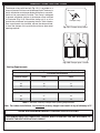
F. Una pantalla de la chimenea debe ser en el lugar cuando el sistema está quemando. Las provisiones para el aire de
combustión adecuado deben ser mantenidas. A menos que otras provisiones para el aire de combustión se proporcionen, la
pantalla tendrá una abertura para la introducción de aire de combustión. El aire de combustión es adecuado cuando todas las
llamas se encrespan en la chimenea y lejos de la pantalla. Cuando se utiliza un recinto de cristal de la chimenea (puerta),
deje las puertas completamente abiertas cuando el sistema es en funcionamiento.
G. Ne retirez pas les plaques signalétiques ou les étiquettes d'avertissement. Ceux-ci sont une composante de sécurité et
d'identifi cation intégrante de cet appareil.
H. Assurez-vous de lire la section de nettoyage et l'entretien et la section de description de la fl amme.

7
FIREPLACE OPERATING SAFETY INFORMATION
A. Adults shall be present when this gas appliance is operating. This unit shall not be left burning when unattended or
while anyone is sleeping.
B. Keep the area of the gas burner system clear and free from combustible materials, gasoline, and other fl ammable
vapors and liquids.
C. Children MUST be supervised when they are in the area of this appliance.
D. DO NOT place any part of the body, clothing, or other fl ammable materials on or near the appliance. Children and adults
should be alerted to the hazard of high surface temperatures and should stay away to avoid burns or clothing ignition.
DO NOT lean over the unit when lighting or when in use.
E. DO NOT use this appliance if any part has been underwater. Immediately call a qualifi ed service technician to inspect
the appliance and to replace any part of the control system and any gas control that has been underwater. Attempted
operation may result in fi re or explosion resulting in property damage, personal injury or loss of life.
F. A fi replace screen must be in place when the system is burning. Provisions for adequate combustion air must be
maintained. Unless other provisions for combustion air are provided, the screen shall have an opening(s) for introduction
of combustion air. Combustion air is adequate when all fl ames curl into the fi replace and away from the screen. When
a glass fi replace enclosure (door) is used, leave the doors fully open when the system is in operation.
G. Do not remove the rating plates or the warning tags. These are an integral safety and identifi cation component of this
appliance.
H. Be sure to read the CLEANING AND SERVICING and FLAME DESCRIPTION sections.

8
U
L
Fig. 8-1 type coupleur rapide de fi l de point culminant d’I
Valve
de
décompression
QCC
Type 1
Valve
Ajustage de précision
en laiton de fi l de
point culminant
Indicateur
de niveau
de liquide
(facultatif)
Écrou de main avec le
fi l de point culminant.
Régulateur
Passage
Tuyau
Volant de commande
main dans le sens des aiguilles d’une montre pour engager les
fi ls et pour serrer jusqu’à ce que douillettement. L’utilisation des
pinces ou de la clé ne devrait pas être nécessaire. Seulement
le propane marqué par cylindres doit être employé.
Pour débrancher: Tournez l’écrou de main dans le sens
contraire des aiguilles d’une montre jusqu’à isolé (fi g. 8-1).
Important: Avant d’employer le unité, et ensuite chaque
fois que le cylindre est enlevé et rattaché,
examinez tous les raccordements pour
déceler les fuites. Arrêtez les valves de unité
et ouvrez la valve principale de cylindre, puis
vérifi ez les raccordements avec de l’eau
savonneux. Réparez toutes les fuites avant
d’allumer le unité.
ATTENTION: Tournez toujours la valve principale de cylindre
de propane au loin après chaque utilisation,
et avant de déplacer le unité et le cylindre, ou
débrancher l’accouplement. Cette valve doit
rester fermée et le cylindre a débranché alors
que l’appareil n’est pas en service, quoique
l’écoulement de gaz soit arrêté par un dispositif
de sûreté quand le coupleur est débranché.
Inspectez soigneusement l’ensemble de tuyau chaque fois
avant que le gaz soit allumé. Un tuyau fi ssuré ou effi loché doit
être immédiatement remplacé.
Si l'appareil est stocké à l'intérieur, le cylindre doit être disconnected
et a enlevé. Des cylindres Disconnected doivent être stockés
dehors, hors de la portée des enfants, avec les prises de valve
fi letées étroitement installées, et ne doivent pas être stockés dans
un bâtiment, le garage, ou n'importe quel autre secteur inclus.
POUR VOTRE SÛRETÉ
a. Ne stockez pas un cylindre de gaz disponible de propane
dessous ou ne vous approchez pas de cet appareil.
b. Ne remplissez jamais cylindre au delà de 80 pour cent de
plein.
c. SI L’INFORMATION DANS “A” ET “B” N’EST PAS SUIVIE
EXACTEMENT, UN FEU CAUSANT LA MORT OU DES
DOMMAGES SÉRIEUX PEUT SE PRODUIRE.
IMPORTANT POUR VOTRE SÛRETÉ
LISEZ ET SUIVEZ TOUS LES AVERTISSEMENTS ÉQUIPÉS DE VOTRE CYLINDRE DE GAZ DE PROPANE.
En actionnant cet appareil avec un cylindre de gaz de propane ON DOIT observer ces instructions et avertissements.
LE MANQUE DE FAIRE AINSI PEUT AVOIR COMME CONSÉQUENCE UNE INCENDIE OU UNE EXPLOSION SÉRIEUSE.
CYLINDRE ET CONDITIONS ET
CARACTÉRISTIQUES DE CONNECTEUR
a. Des cylindres et les valves de gaz de propane doivent être
maintenus en bon état et doivent être remplacés s’il y a
des dommages évidents au cylindre ou à la valve.
b. Ce unité, une fois utilisé avec un cylindre, devrait être relié à
un gallon de la norme 5 (20lb.) cylindre de gaz de propane
équipé d’un OPD (remplissez au-dessus du niveau le
dispositif d’empêchement). L’OPD a été exigé sur tous les
cylindres vendus depuis octobre 1.1998 pour empêcher le
remplissage excessif.
c. Les dimensions de cylindre devraient être approximativement
12"(30.5cm) de diamètre et 18" (45.7cm) hauts. Des
cylindres doivent être construits et marqués selon les
caractéristiques pour des cylindres de gaz de propane du
département des ETATS-UNIS du transport (D.O.T.) ou
le niveau national du Canada, du CAN/CSA-B339, des
cylindres, des sphères et des tubes pour le transport des
marchandises dangereuses.
d. Le cylindre doit inclure un collier pour protéger la valve
de cylindre et le circuit d’alimentation de cylindre doit être
assuré le retrait de vapeur.
e. Le montage du régulateur de pression et le fl exible (Fig. 8-1)
fourni avec cet appareil au gaz en plein air (modèles au
propane seulement) doit être utilisé. Assemblées d'origine et
régulateur de pression et le tuyau de remplacement doivent
être ceux spécifi és par le fabricant pour le raccordement d'un
dispositif de cylindre de liaison identifi ée comme de type I
par le ANSI Z 21.58/CGA 1.6 (voir liste des pièces pour les
informations de commande).
f. La valve de cylindre de gaz de propane doit être équipée
d’un dispositif d’accouplement de raccordement de
cylindre, décrit comme type I dans la norme défi nie dans le
e. de paragraphe ci-dessus. Ce dispositif est généralement
décrit comme coupleur rapide de fi l de point culminant.
g. Si votre cylindre de gaz de propane vient avec une prise
de la poussière, placez le bouchon anti-poussière sur la
sortie de valve de cylindre toutes les fois que le cylindre
n’est pas en service.
OPÉRATION DE COUPLEUR RAPIDE
Pour relier le regulator/hose à l’ajustage de précision de
valve de cylindre de gaz de propane: Serrez l’écrou de main
sur le régulateur au-dessus de l’ajustage de précision de fi l
de point culminant sur la valve de cylindre. Tournez l’écrou de
1
2
3
4
e. Le régulateur de pression et l’ensemble de tuyau utilisé
doivent assortir les spécifi cations pour le type I par ANSI
Z 21.58/CGA 1.6 (voir la fi gue. 8-1).
UTILISATION SÛRE ET ENTRETIEN DES CYLINDRES DE GAZ DE PROPANE

9
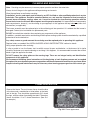
U
L
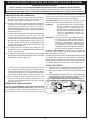
Fig. 9-1 Type I Acme thread quick coupler
Pressure
relief
valve
QCC
Type 1
valve
Brass Acme
thread fi tting
Liquid level
indicator
(optional)
Hand nut with Acme
thread
Regulator
Vent
Hose
Hand wheel
The use of pliers or a wrench should not be necessary. Only
cylinders marked “propane” may be used.
To disconnect: Turn the hand nut counterclockwise until
detached (Fig. 9-1).
Important: Before using the unit, and after each time
the cylinder is removed and reattached,
check the hose for wear (see a.) and check
all connections for leaks. Turn off the unit
valves and open the main cylinder valve,
then check connections with soapy water.
Repair any leaks before lighting the unit.
CAUTION: Always turn the propane cylinder main valve
off after each use, and before moving the unit
and cylinder or disconnecting the coupling.
This valve must remain closed and the
cylinder disconnected while the appliance
is not in use, even though the gas fl ow is
stopped by a safety feature when the coupler
is disconnected.
Carefully inspect the hose assembly each time before the
gas is turned on. A cracked or frayed hose must be replaced
immediately.
If the appliance is stored indoors, the cylinder must be
disconnected and removed. Disconnected
cylinders must be
stored outdoors, out of the reach of children, with threaded
valve plugs tightly installed, and must not be stored in a
building, garage, or any other enclosed area.
FOR YOUR SAFETY
a. DO NOT store a spare propane-gas cylinder under or
near this appliance.
b. NEVER fi ll the cylinder beyond 80-percent full.
c. IF THE INFORMATION IN a. AND b. IS NOT FOLLOWED
EXACTLY, A FIRE CAUSING DEATH OR SERIOUS
INJURY MAY OCCUR.
IMPORTANT FOR YOUR SAFETY
READ AND FOLLOW ALL WARNINGS PROVIDED WITH THE PROPANE-GAS CYLINDER.
When operating this appliance with a propane-gas cylinder, these instructions and warnings MUST be observed.
FAILURE TO DO SO MAY RESULT IN A SERIOUS FIRE OR EXPLOSION.
CYLINDER/CONNECTOR REQUIREMENTS
a. Propane-gas cylinders, valves, and hoses must be
maintained in good condition and must be replaced if
there is visible damage to either the cylinder or valve. If the
hose is cut or shows excessive abrasion or wear, it must
be replaced before using the gas appliance (see e.).
b. This unit, when used with a cylinder, should be connected
to a standard 5-gallon (20 lb.) propane-gas cylinder
equipped with an OPD (Overfi ll Prevention Device).
The OPD has been required on all cylinders sold since
October 1,1998, to prevent overfi lling.
c. Cylinder dimensions should be approximately 12" (30.5
cm) in diameter and 18" (45.7 cm) high. Cylinders must
be constructed and marked in accordance with the
Specifi cations for Propane Gas Cylinders of the U.S.
Department of Transportation (D.O.T.) or the National
Standard of Canada, CAN/CSA-B339, Cylinders,
Spheres, and Tubes for Transportation of Dangerous
Goods.
d. The cylinder used must include a collar to protect the
cylinder valve, and the cylinder supply system must be
arranged for vapor withdrawal.
e. The pressure regulator and hose assembly (Fig. 9-1)
supplied with this outdoor gas appliance (L.P. models
only) must be used. Original and replacement pressure
regulator and hose assemblies must be those specifi ed by
the manufacturer for connection with a cylinder connecting
device identifi ed as Type I by the ANSI Z 21.58/CGA 1.6
(see PARTS LIST for ordering information).
f. The propane-gas cylinder valve must be equipped with a
cylinder connection coupling device, described as Type I
in the standard defi ned in paragraph e. above. This device
is commonly described as an Acme thread quick coupler.
g. If the propane-gas cylinder comes with a dust plug, place
the dust cap on the cylinder valve outlet whenever the
cylinder is not in use.
QUICK COUPLER OPERATION
To connect the regulator/hose assembly to the propane-
gas cylinder valve fi tting: Press the hand nut on the regulator
over the Acme thread fi tting on the cylinder valve. Turn the hand
nut clockwise to engage the threads and tighten until snug.
e. The pressure regulator and hose assembly used must
match the specifi cation for Type I by ANSI Z 21.58/CGA
1.6 (see Fig. 9-1).
SAFE USE & MAINTENANCE OF PROPANE GAS CYLINDERS

10
Real Fyre gas burner systems must be installed only in an approved fi replace with the minimum
fi rebox dimensions and venting requirements met (see following tables). Adequate ventilation is
absolutely necessary.
SPECIFICATIONS
Product Specifi cations
Specifi cation Value Qty.
Igniter battery type AA battery 1
Table 2 - Technical Data
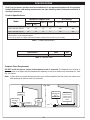
Fireplace Floor Requirement
DO NOT install this burner system if the fi replace hearth is recessed. The fi replace fl oor must be at
the same level as or higher than the fi replace front opening. An ash lip or recess may not exceed
3
/
4
". See
Fig. 10-1 below.
Note: If glass doors are used: the fi replace fl oor must not be blocked by the door frame; the frame must
have openings to allow for fresh air circulation.
Fig. 10-1
Fireplace
fl oor
Fireplace
opening
(burner
system)
ASH LIP OR
RECESS
ABOVE
3
/4"
NOT
PERMITTED
Max.
3
/4
"
ASH LIP OR
RECESS UP
TO
3
/4"
PERMITTED
DEPTH to be
measured as
shown (when
ash lip/recess
exists)
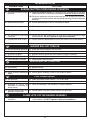
Table 1 - Product Specifi cations
Model
Minimum Fireplace Size BTU Rating
Width*
Depth ‡ Height Nat. Gas L.P. Gas
Front Rear
†
G52-18/20 (18" log set) 28" 20" 15" 17" 46k 36k
G52-24/30 (24" log set) 32" 24" 15" 17" 55k 46k
G52-24/30 (30" log set) 34" 28" 15" 17" 55k 46k
* These required widths allow for centering of the unit.
†
Rear width is at corresponding depth.
‡ If an ash lip exists, the depth requirement begins inside of the lip (see Fig. 10-1 below).

11
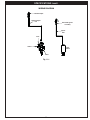
SPECIFICATIONS (cont.)
WIRING DIAGRAM
Fig. 11-1
Inlet
Valve
Outlet
Thermocouple
line
Electrode igniter
assembly
Igniter
wire
Igniter
module
Thermocouple

12
Damper clamp
Set screw
Open
Closed
DAMPER CLAMP INSTRUCTIONS
Fig. 12-1 Damper clamp detail
Fig. 12-2 Damper open / closed
The damper clamp with hex bolt (
Fig. 12-1) is provided as a
means to prevent full closure of the damper blade. The clamp is
easily attached to most damper blades with pliers or a wrench,
and must be permanently installed. The clamp is designed
to prevent accidental closure of the damper when installed
as illustrated (Fig. 12-2). Should the clamp not fi t, or fail to
provide the permanent vent opening listed in Table 3 below,
have a permanent stop installed, remove the damper blade,
or have the damper cut to provide the minimum permanent
opening required.
THE DAMPER MUST BE COMPLETELY OPENED WHEN OPERATING THIS GAS APPLIANCE TO
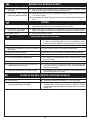
ACHIEVE THE BEST VENTILATION POSSIBLE.
Minimum permanent free opening area of chimney damper for venting (sq. in.)
For factory-built fi replaces
Chimney height 18/20" 24/30"
15' 21 24
20' 18 21
30' 14 16
For masonry-built fi replaces
15' 30 35
20' 27 32
30' 25 29
Note: For indoor installations, the minimum chimney height from hearth to top of chimney is 15'.
Table 3 - Minimum Chimney Damper Vent Opening Requirements
Venting Requirements
THESE ARE MINIMUM DAMPER OPENING SPECIFICATIONS.

13
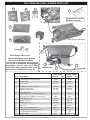
Note: Photos not to scale
Replacement parts can be ordered
from your local Real Fyre dealer.
18/20" burner model shown
Bottom view
13
14
12
Igniter
assy
9
11
4
18/20" model 24/30" model
Item Description Part No. Qty. Part No. Qty.
1. Electrode igniter assembly (w/wire) EA-05 1 EA-05 1
2. Thermocouple SV-30-1 1 SV-30-1 1
3. Igniter module OCR-34-21 1 OCR-34-21 1
4. Control valve (natural or propane) SV-34 1 SV-34 1
5.
or
Regulator (natural gas)
Regulator (propane gas)
PR-1NAT
PR-1LP
1
1
PR-1NAT
PR-1LP
1
1
6. Valve extension kit
(includes extension rod, knob, bracket & nut)
EH-15 1 EH-15 1
7. Flex connector (w/ adapter), 1/2" O.D. x 24" 3035 1 3035 1
8. Radiant booster grid SC-10 1 SC-15 1
9. Glowing embers A EM-22A 1 EM-21A 1
10. Glowing embers B EM-22B 1 EM-21B 1
11. Bryte coals EM-11 1 EM-11 1
12.
or
Sand, #16 (natural gas burner)
Lava granules (propane gas burner)
400071-8
LF-5
1
1
400071-10
LF-5
1
2
13. Lava granules (fi replace fl oor) LF-4 1 LF-4 1
14. Damper clamp DC-1 1 DC-1 1
6
Thermocouple
10
7
8
The log set is purchased and packaged
separately; contact your local Real
Fyre dealer when ordering. Refer to the
instructions included with the log set.
Igniter battery included
with burner system.
1
2
3
5
G52 STAINLESS STEEL BURNER PARTS LIST

14
REFER TO THE PARTS LIST WHEN FOLLOWING INSTALLATION
INSTRUCTIONS.
18/20" burner model shown here.
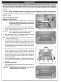
BURNER INSTALLATION
Important: Ensure that the gas supply line is located out
of pathways where people may trip over it or in
areas where the line may be subject to accidental
damage (if applicable).
1. MAKE SURE FIREPLACE GAS SUPPLY IS TURNED OFF.
2. Locate the gas-supply stub inside the fi replace and remove
the cap, if attached (reference Fig. 14-1).
CAUTION: When removing the cap, make sure the stub does not
turn, loosening the connection inside the wall.
3. Place the burner system in the fi replace. Center the burner
from left to right in the fi replace. See Fig. 14-2.
Note: The tabs located on the burner are for spacing and air
circulation. See Fig. 14-3.
4. Be sure gas to the fi replace is off. Remove the adapter
connected to the fl ex connector (pre-installed on the burner
system). Attach the adapter to the gas-supply stub using a
pipe compound resistant to all gasses. Tighten securely. Then
attach the open end of the fl ex connector to the adapter. Tighten
securely (see Fig. 14-1).
5. LEAK TEST: Turn on the fi replace gas supply, and test at
all connections for leaks using the appropriate soapy water
solution. If bubbles appear, a leak is present. Turn off the
gas and tighten at all connections. Repeat until no leaks are
present. If a leak persists, turn off the gas supply and contact
the local gas company or dealer. NEVER USE A FLAME TO
CHECK FOR LEAKS.
6. At this stage the igniter battery is to be installed. Reference
the INSTALLING/REPLACING IGNITER BATTERY section
for details.
7. Decorative Heat Shield
Place the decorative heat shield over the igniter module as
shown in Fig. 14-4.
CAUTION: THE DECORATIVE HEAT SHIELD WILL BE HOT
DURING AND AFTER OPERATION.
The Real Fyre burner system must be installed by a qualifi ed professional service technician. Instructions
must be followed carefully to ensure proper performance and full benefi t from the burner system. Check to be
sure the burner system is designed and labeled for the type of gas (natural or propane gas) supplied to
the fi replace. Fireplace fl oor must be level, clean, and smooth (see FIREPLACE SAFETY INFORMATION
section).
WARNING: Failure to position the parts in accordance with these diagrams or failure to use only parts
specifi cally approved with this appliance may result in property damage or personal injury.
INSTALLATION
Fig. 14-2 Center burner in fi replace
Fig. 14-1 Connect gas supply
Flex connector
Adapter
Gas supply stub
Fig. 14-3 Burner tabs detail
Tabs
Fig. 14-4 Place heat shield

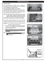
15
Fig. 15-1 Place lava granules (fl oor)
INSTALLATION (cont.)
LIGHTING TEST
Prior to proceeding with installation, perform a lighting test
(see lighting instructions for lighting your burner). Allow the
unit to completely cool after testing.
LAVA GRANULES (FIREPLACE FLOOR)
Spread the supplied lava granules on the fl oor of the fi replace,
around the front and sides of the burner system (see Fig. 15-1).
The lava granules may be placed around the igniter module.
Leave the front of the module clear for access.
Note: DO NOT place any lava granules on the burner
system, below it, behind it, behind the igniter
module, or under the knob at the front of the valve.
SAND/LAVA GRANULES PLACEMENT (BURNER)
The sand/lava granules supplied with the unit are specially
selected for use with either natural or propane gas. They
maximize fl ame distribution and provide a cleaner burning fl ame.
CAUTION: Use only sand for natural gas burners and lava
granules for propane gas burners.
1. Fill the burner pan completely with the sand/lava granules
(see Fig. 15-3). DO NOT cover the thermocouple or
electrode igniter assembly.
2. Slope the sand/lava granules at the same angle as the
burner pan. This is important to ensure quiet lighting and
even fl ame distribution. See Fig. 15-4.
Note: For sand on a natural gas burner only: pack the
sand tightly. (Not applicable for lava granules /
propane models.)
Fig. 15-3 Place sand/lava granules (burner)
Fig. 15-4 Sand/lava granules detail
Fill sand
to this line
Fig. 15-2 Granules detail - keep knob clear
Fill pan with
sand / lava
granules &
slope with pan.
For Sand Only:
Pack Tightly.
Fill granules
to this line
NAT. GAS MODELS
L.P. GAS MODELS
DO NOT cover
thermocouple
or igniter assy
DO NOT cover
thermocouple
or igniter assy

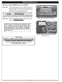
16
INITIAL GLOWING EMBERS (A) PLACEMENT
Important: The supplied embers are to be applied at several
stages of installation. You may end up with some
unused embers at the end of installation. If so,
store them for later use/replacement.
Sprinkle a portion of the glowing embers A lightly and evenly
over the entire surface of the sand/lava granules as shown in Fig.
16-1. Break up any clumps that may have developed during
shipment. Store unused embers for later use/replacement.
Important: Place the glowing embers A lightly and evenly
as shown. DO NOT over apply.
INSTALLATION (cont.)
Fig. 16-1 Place glowing embers A
Place embers A as shown
IMPORTANT
EMBER PLACEMENT IS NOT COMPLETE AT THIS STAGE.
REFER TO THE NEXT PAGE AND THE SEPARATE
INSTRUCTIONS PACKED WITH YOUR LOG SET TO
CONTINUE INSTALLATION.
KEEP SAND, LAVA GRANULES, EMBERS, AND
ALL FOREIGN OBJECTS AWAY FROM THE
THERMOCOUPLE AND IGNITER ASSEMBLY
DURING MEDIA PLACEMENT AND AT ALL TIMES.
SEE FIG. 16-2.
Fig. 16-2 Keep thermocouple and igniter
assembly clear
DO NOT cover
thermocouple
or igniter assy

17
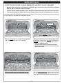
INSTALLATION (cont.)
LOG SET, BOOSTER GRID, GLOWING EMBERS (B), AND BRYTE COALS PLACEMENT
• Read all safety warnings and important information in this manual and the instructions supplied
with the log set to ensure proper placement.
• DO NOT add any additional embers to this setup. Any additional embers will cause unsafe operation.
• Your log set design may slightly vary from the images shown here, but initial placement is the same.
All models begin with the bottom log and ember placement shown below. To complete log placement continue
to the instructions supplied with your specifi c log set.
Ember stop
(part of frame)
1
1A
1B
Place the rear log (log #1) as shown. The log should be
slid back on the burner until it hits the backstop.
The ember stop at the front of the shelf serves to confi ne
the embers B in place. Place and pack a level amount of
embers B on the shelf in front of the rear log as shown.
• PACK THE EMBERS DOWN
(to reduce heat transfer to components below).
• Save a small amount of embers for placement on the
radiant booster grid.
Place embers B as shown
Place the radiant booster grid as shown above and in the
next image. The grid should rest against the rear log. The
ember stop has notches to properly align the grid in place.
Ensure the embers are level and packed in place.

18
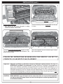
CAUTION: BURN HAZARD! Logs will remain hot for some time after use. If you need to reposition
any log to maintain the proper layout, use heat-resistant gloves or allow logs adequate time
to cool before handling.
Important: Adequate ventilation is absolutely necessary! Adequate spacing between the logs is
NECESSARY and MUST be maintained. Provided signifi cant, noticeable sooting does not
occur, some fl exibility is possible in top log placement to suit your individual preference. If you
experience a continued accumulation of black carbon (soot) on your logs it is an indication of
incomplete combustion and you should move the effected log(s) so as to minimize the fl ame
contact on the effected log(s). If signifi cant sooting continues, stop using this gas log set. Read
the instructions supplied with the log set completely and carefully.
FOLLOW THE INSTRUCTIONS INCLUDED WITH YOUR SPECIFIC LOG SET TO
COMPLETE LOG AND BRYTE COALS PLACEMENT.
1C
Place the remaining amount of embers B across the grid
as shown.
Place remaining embers B as shown
Radiant booster grid detail:
• Rest against rear log, orient with grid "C" facing
forward, and within notches/tabs.
Grid "C"
facing
forward
Grid within
notches/tabs
1B
2A
2
Gently bring together the rear and front logs to create a
tight fi t around the grid.
Place the left and right front log pieces (log #2) as shown.
The two logs should be touching and centered on the
burner from left to right.
INSTALLATION (cont.)
(COLO sets use one front log)
2

19
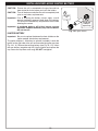
INSTALLING/REPLACING IGNITER BATTERY
CAUTION: Ensure the unit is connected to the gas line and has
been tested for leaks before you insert the battery.
CAUTION: Turn off the burner and allow the unit to completely cool
prior to any battery replacements.
Important: Prior to inserting the battery, always apply a small
amount of dielectric grease to both ends of the battery.
This will ensure conductivity and prevent moisture from
affecting the contact.
Important: A low/dead battery will affect burner system
operation. Replace the battery any time the burner
will not turn on.
IGNITER BATTERY
Important: Be sure to replace the decorative heat shield over the
igniter module after battery replacement.
The igniter requires 1 AA battery to operate (included). Locate the
igniter on the right side of the unit and unscrew the igniter cap (see
Fig. 19-1, A). Remove the existing battery (see Fig. 19-1, B). Insert
the new battery (negative end fi rst) into the igniter and replace the
cap. Screw the cap down until snug. DO NOT overtighten.
+
_
Fig. 19-1 Igniter battery
Install new
battery &
replace cap
B
Unscrew
cap
A

20
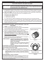
AVERTISSEMENT: GARDEZ VOTRE DISTANCE LORS DE
L’ÉCLAIRAGE.
1. ARRÊT! Lire les consignes de sécurité ci-dessus.
2. S'assurer que le bouton de contrôle du gaz est en position OFF (éteindre)
avant de séquence d'éclairage à partir la position.
3. Appuyez et maintenez enfoncé le bouton d'allumage électronique (voir
Fig. 20-1). L'allumeur commence à susciter un déclic rapide.
4. Tout en maintenant le bouton d'allumage dans, vérifi ez que
l'électrode est étincelles. Ensuite, tournez la commande de gaz
dans le sens anti-horaire à la position ON (allumer), appuyer et
maintenir pendant 15 secondes (voir Fig. 20-2). Votre brûleur doit
allumer.
Maintenir le bouton pendant 15 secondes permet à la soupape de
sécurité et pour activer le brûleur reste allumé
AVERTISSEMENT: Si le brûleur ne s'allume pas dans les 5 secondes,
appuyez immédiatement sur le bouton de
commande et tournez dans le sens horaire à la
position OFF (éteindre).
Attendez environ cinq (5) minutes pour laisser
échapper tout le gaz, et répétez les étapes 3-4
ci-dessus.
Si votre brûleur ne s'allume pas, appuyer sur le bouton de commande
et tournez dans le sens horaire à la position OFF (éteindre) et contactez
votre revendeur ou fournisseur de gaz.
Note: La hauteur de fl amme est réglable via le bouton de commande.
Note: Pour allumer manuellement le brûleur, placez une allumette
allumée sur la surface des braises près du brûleur (ne la tenez pas
dans votre main) ou utilisez un allumeur à tige longue / briquet au
butane à long manche allumé. Continuez ensuite avec la procédure
ci-dessus.
POUR ARRÊTER LE GAZ À L'APPAREIL
Pour éteindre le brûleur à gaz, appuyer sur le bouton de contrôle du gaz
et tourner dans le sens horaire à la position OFF (éteindre) (voir Fig. 20-2).
Assurez-vous que le bouton de commande est tourné complètement hors
tension pour éviter toute fuite de gaz.
AVERTISSEMENT: SI VOUS NE SUIVEZ PAS CES INSTRUCTIONS À LA LETTRE, UN INCENDIE OU UNE
EXPLOSION POURRAIENT S'ENSUIVRE, CAUSANT DES DOMMAGES MATÉRIELS,
DES BLESSURES OU DES PERTES DE VIE.
A. Utilisez uniquement votre main pour enfoncer ou tourner le bouton de contrôle du gaz. N'utilisez jamais d'outils.
Si le bouton ne s'enfonce ou ne tourne pas à la main, n'essayez pas de le réparer. Appeler un technicien
qualifi é. Une force excessive ou une tentative de réparation peut provoquer un incendie ou une explosion.
B. AVANT D'ALLUMER, sentez tout autour de l'unité de surface pour le gaz. Assurez-vous de sentir près du
plancher, car certains gaz sont plus lourds que l'air et se déposent sur le sol.
QUE FAIRE SI UNE ODEUR DE GAZ
1. Coupez le gaz à l'appareil.
2. Éteindre toute fl amme nue.
3. Si l'odeur persiste, appelez immédiatement votre fournisseur de gaz ou le service des incendies.
C. N'utilisez pas cet appareil si une partie quelconque a été submergée. Appelez immédiatement un technicien
qualifi é pour inspecter l'appareil et remplacer toute pièce du système de contrôle et tout contrôle de gaz
immergé. Toute tentative d'utilisation peut provoquer un incendie ou une explosion, entraînant des dommages
matériels, des blessures ou la mort.
POUR VOTRE SÉCURITÉ, LIRE AVANT D'ALLUMER
INSTRUCTIONS D'ALLUMAGE
Fig. 20-1
Bouton d'allumage
OFF
ON
ÉTEINDRE
ALLUMER
Fig. 20-2
Bouton de la valve
La page est en cours de chargement...
La page est en cours de chargement...
La page est en cours de chargement...
La page est en cours de chargement...
La page est en cours de chargement...
La page est en cours de chargement...
-
 1
1
-
 2
2
-
 3
3
-
 4
4
-
 5
5
-
 6
6
-
 7
7
-
 8
8
-
 9
9
-
 10
10
-
 11
11
-
 12
12
-
 13
13
-
 14
14
-
 15
15
-
 16
16
-
 17
17
-
 18
18
-
 19
19
-
 20
20
-
 21
21
-
 22
22
-
 23
23
-
 24
24
-
 25
25
-
 26
26


Real Fyre G52 Le manuel du propriétaire
- Catégorie
- Cheminées
- Taper
- Le manuel du propriétaire
- Ce manuel convient également à
dans d''autres langues
- English: Real Fyre G52 Owner's manual
Documents connexes
-
Real Fyre PB Le manuel du propriétaire
-
-
-
-
-
-
Real Fyre GR47 Le manuel du propriétaire
-
-
-
Autres documents
-
R.H. Peterson American Fyre Designs Unvented Series Installation & Owner's Manual
-
Fire Magic Sideburner Manuel utilisateur
-
FireMagic 32874-1(P) Installation And Operating Insctruction Manual
-
American Hearth Vented Slope Glaze Burner (VFM/VSR18/24/30) Le manuel du propriétaire
-
-
Empire VSM-18-1 Le manuel du propriétaire