SportsArt Fitness E850 Le manuel du propriétaire
- Taper
- Le manuel du propriétaire

E850 OWNER’S MANUAL CONTENTS
1. INTRODUCTION .............................................................................. 2
2. SAFETY PRECAUTIONS ................................................................ 3
3. LIST OF PARTS ............................................................................... 5
4. ASSEMBLE THE PRODUCT ........................................................... 7
STEP 1 Unbox the Unit ........................................................................ 7
STEP 2 Assemble the Pedestal............................................................ 8
STEP 3 Install the Upper Cover............................................................ 9
STEP 4 Install Stride Linkages and Footplate Carriages. .................... 9
STEP 5 Install Left/Right Supports ....................................................... 10
STEP 6 Secure the Rail Base Cover ................................................... 11
STEP 7 Move the Unit into Place ......................................................... 12
STEP 8 Level the Unit .......................................................................... 13
STEP 9 Ground Wire Connection ........................................................ 14
STEP 10 Avoid Safety Hazards ............................................................ 14
5. MECHANICAL ADJUSTMENTS ...................................................... 15
6. UNDERSTAND THE E850 DISPLAY ............................................... 16
DISPLAY Overview .............................................................................. 16
DISPLAY Windows ............................................................................... 17
DISPLAY Keys ..................................................................................... 17
DISPLAY Specications ....................................................................... 18
7. OPERATE THE E850 ELLIPTICAL TRAINER ................................. 18
OPERATION QUICK START Mode ..................................................... 18
OPERATION START Mode .................................................................. 19
OPERATION Cool Down ...................................................................... 21
OPERATION Workout Programs ......................................................... 21
OPERATION User Preferences and Product Information .................... 23
8. ABOUT HEART RATE DETECTION ................................................ 25
HEART RATE Telemetry ...................................................................... 25
HEART RATE Contact ......................................................................... 25
9. GUIDELINES FOR EXERCISE ........................................................ 26
10. MAINTENANCE ............................................................................. 27
MAINTENANCE Lubricate the Shoulder Area ..................................... 27
MAINTENANCE Clean the Glide Rail .................................................. 28
MAINTENANCE Schedule ................................................................... 29
MAINTENANCE Task List (Elliptical Trainers) ..................................... 30
MAINTENANCE One-Year Maintenance Log ...................................... 31
MAINTENANCE Electronics Block Diagram ........................................ 32
11. SAFETY PRECAUTIONS IN FRENCH .......................................... 33

2
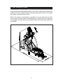
1. INTRODUCTION
Congratulations on your purchase of one of the nest exercise products on the market
today, the SportsArt E850 elliptical trainer. Constructed of high quality materials and
designed for years of reliable usage, this product was made to become an integral
part of your commercial tness venue.
Before this product is assembled or operated, we recommend that you famil-
iarize yourself with this manual. Understanding the correct methods of assembly
and operation will help ensure that exercisers obtain their tness goals safely and
successfully.

3
2. SAFETY PRECAUTIONS
This product was designed and built for optimum safety. However certain precau-
tions apply during the use of this product. Please note the following safety
precautions:
• Please read the entire manual before assembly and operation. Make
sure the product is installed and operated as instructed in this manual.
• Assemble and operate the product on a solid, level surface. Do not use
outdoors or near water, including pools and saunas.
• Check the product before every use. Make sure all parts are assem-
bled, and all fasteners are tightened. Do not use the product if it is disas-
sembled in any way.
• Wear proper workout clothing. Do not wear loose clothing. Do not wear
shoes with leather soles or high heels. Tie all long hair back. Do not go
barefoot on this product.
• Keep away from moving parts. Moving parts may or may not stop imme-
diately if an object becomes caught or impedes normal motion.
• Use this product only for its intended purpose as described in this
manual.
• Be careful when mounting and dismounting the unit.
• Never operate this product if it has been damaged in any way. If it is
not working properly, or has been dropped or damaged, contact a service
technician for repairs.
• Do not use accessories that are not specically recommended by the
manufacturer. Such parts might cause injuries or cause the unit to fail.
• Keep all air ventilation areas free of blockage. Never drop or insert any
object into any opening.
• Do not operate where aerosol (spray) products are being used or where
oxygen is being administered.
• This product is not intended for use by persons (including children) with
reduced physical, sensory, or mental capabilities, or by people who are
otherwise decient in product knowlege or experience. If such people use
this product, they should be given training and be supervised at all times
by someone responsible for their safety.
• Children should be supervised to ensure that they do not play on or
near the product.
• The user weight limit for this product is 180 kg, 400 lb. At maximum
resistance, level 20, this product meets standards for users up to 150 kg,
330 lb.
CAUTION: If you feel any pain or abnormal sensations, STOP YOUR
WORKOUT and consult your physician immediately. Work within your
recommended exercise level. DO NOT work to exhaustion. Before beginning
any exercise program, you should consult with your doctor. It is recommended that
you undergo a complete physical examination.
WARNING! Heart rate monitoring systems may be inaccurate. Too much exercise
may result in serious injury or death. If you feel faint, stop exercising immediately.

4
2. SAFETY PRECAUTIONS (CONTINUED)
Note: This equipment has been tested and found to comply with the limits for a Class
B digital device, pursuant to part 15 of the FCC Rules. These limits are designed to
provide reasonable protection against harmful interference in a residential instal-
lation. This equipment generates, uses and can radiate radio frequency energy and,
if not installed and used in accordance with the instructions, may cause harmful
interference to radio communications. However, there is no guarantee that inter-
ference will not occur in a particular installation. If the user desires to correct the
interference, it is at the user’s own expense.
WARNING! Only qualied technicians should be allowed to contact electrical
components such as circuit boards. Some components carry an electrical charge
even after use has been discontinued or the product has been unplugged. For
products with power cords, turn off unit power, wait ve minutes, then disconnect
the power cord from the power socket. For products without power cords, let the unit
sit without use for ve minutes. Only after taking such precautions should covers be
removed and electrical components be accessed.

5
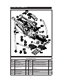
3. LIST OF PARTS
Assembly Parts
No. Name Qty. No. Name Qty.
A1 Main body 1 A6 Left footplate assembly 1
A1A Rail base cover 1 A7 Right footplate assembly 1
A2
Small cover
1 A8
Base covers for right
support
1
A3 Upper cover 1 A9 Base covers for left support 1
A4 Right support 1 A10 Hardware kit 1
A5 Left support 1

6
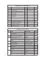
Components on the Product
No. Name Specication Notes
41
Inner hex screw M8*L20
Spring washer M8
Serrated washer D18*d8.5*t2.0*19T
42 Mushroom top Phillips screw M4*L16
43
Inner hex screw M8*L25
Spring washer M8
Washer D17*d8.3*t1.0
44
Inner hex screw M6*L15
Serrated washer D20*d6.2*t2.0*19T
45
Inner hex screw 5/16”*L2-1/4 inch
Seat roller washer D17*d8*t2.0
46
Roller axle
Flat washer D21*d10.5*t2
Lock nut M10
47
PU sheath D12*D8*L45
Axle M5*L71
Flat washer D17*d8.3*t1
Mushroom top inner hex screw M5*6
Components in the Hardware Kit
No. Name Qty. Specication Notes
33 Mushroom top Phillips screw 6 M4*L16
34 Phillips screw 4 M5*P0.8*L10
35 Left/right adjustment rod cover 2
36 Screw insert 4
37 M10 nut cap 2
38 Screw cap 2
L-shaped Allen wrench 1 M6
L-shaped Allen wrench 2 M4
Double open-end wrench 1 8*17
Double open-end wrench 1 13*19
T-shaped Allen wrench 1 M5
Screwdriver shank 1 at and Phillips
Screwdriver handle 1 green

7
4. ASSEMBLE THE PRODUCT
Follow instructions below to assemble this product. Note that in this manual
the words “left” and “right” are used to refer to the product and its parts. As
such, these designations correspond to the “left” and “right” sides of a person
in position to exercise on this product. Also, for brevity, the word “screws” is
used where screws, washers, and other hardware may be involved.
STEP 1 Unbox the Unit
Please follow instructions A through D to remove packaging material and to
place the unit on top of the flattened cardboard.
A. Remove the box top and the plastic sheet.
B. Start working from above, first removing Styrofoam (2) above the unit.
C. Lift Styrofoam (3) on both sides of the unit upward to remove it. Place
parts aside separately.
D. Lift the pedestal to remove the Styrofoam (1) in the middle.

8
STEP 2 Assemble the Pedestal
Please follow instructions
(a) through (b) to assemble
the pedestal.
(a) First, remove screws
(41) from the pedestal
mount on the main body
(A1).
(b) Push the pedestal up to
the vertical position while
preventing the data cable
from getting pinched.
(c) Secure screws (41), first
in area (A), then in area
(B).

9
STEP 3 Install the Upper Cover
Please follow instructions (a) through (d) to install the upper cover.
(a) Slide the water guard up the pedestal. (This ring must be placed above
the upper cover.)
(b) Install the
upper cover and
secure it with
screw (33).
(c) Install the
small cover (A2)
and secure it with
screw (33).
(d) Slide the water
guard down the
pedestal until it
fits snugly against
the covers.
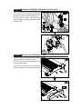
STEP 4 Install Stride Linkages and Footplate Carriages
Please follow steps (a) through (f) to install stride linkages and footplate
carriages on both sides of the product.
(a) Remove bolts (45) from the bushing on the stride adjustment mechanism.
(b) Align the hole in the stride linkage with the bushing on the stride adjustment
mechanism, and
press the stride
linkage into place
on the bushing.
Secure the stride
linkage with bolts
(45). Then insert
the stride linkage
cover (35) into
place. Follow the
same procedure
on both sides.
(c) Remove bolts
(46) from the
vertical arms on
both sides.
(d) Remove
screws (47) from
the left footplate
carriage (A6).

10
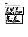
STEP 5 Install Left/Right Supports
Please follow
instructions (a) through
(f) to install left and
right supports.
(a) Remove screws and
remove covers from the
top of the left and right
supports.
(b) Remove screws (43)
(44) from both sides.
(c) Put left and right
supports (A4,A5) into
place and loosely
secure screws (43) at
the top. Do not fully
secure these screws
yet.
(d) First, secure screws
(44) at the base of the
supports (A4,A5). Then
go back to the top and
secure screws (43).
STEP 4 Install Linkages/Carriages (Continued)
(e) Insert the front of the footplate carriage into
the vertical arm. Align it with the hole and use
bolt (46) to secure it into place. Then insert caps
(37, 38) into place.
(f). Lubricate the area where the rod contacts
the bushing, hold the footplate carriage into
place, and secure it with screw (47). Perform
the same actions on both sides of the product.

11
STEP 6 Secure the Rail Base Cover
Please follow instructions (a) through
(b) to install the rail base cover.
(a) First, insert screw inserts (36) into
the rail base plate.
(b) Set the rail base cover (A1A) in
place and secure it with screws (33).
STEP 5 Install Left/Right Supports (Continued)
(e) Put support base covers (A8,A9)
into place on both supports (A4,A5),
and secure them with screws (34).
(f) Set upper covers into place on
both supports, and secure them with
screws (42).

12
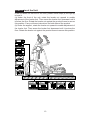
STEP 7 Move the Unit into Place
Follow steps (a) through (c) to move the unit into place for use.
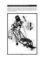
(a) Stand behind the unit. Grasp the glide track rods as shown.
(b) Lift up. (To avoid injury, always use proper lifting techniques.)
(c) Push while using the transport wheels to roll the unit into place.

13
STEP 8 Level the Unit
If the unit does not rest flat on the floor, please follow steps (a) through (b)
to level it.
(a) Under the front of the unit, rotate the leveler nut upward to enable
adjustment of the leveler foot. Then screw the leveler foot downward until it
touches the floor. Rotate the leveler nut against the product frame to secure
this position. Carry out these instructions on both sides of the product.
(b) Under the support, rotate the leveler nut upward to enable adjustment of
the leveler foot. Then screw the leveler foot downward until it touches the
floor. Rotate the leveler nut against the product frame to secure this position.

14
STEP 10 Avoid Safety Hazards
While the product is in use, be careful to avoid getting pinched by or wedged
against moving parts. In particular, do not insert fingers or other body parts
into the stride adjustment area or the opening in the front covers. Prevent
injuries to yourself and others by employing safe operating practices at all
times.
STEP 9 Ground Wire Connection
The ground wire and
the following instructions
are required to meet
European safety
regulations. The ground
wire is not required in
North America.
Overview: To prevent
electrical shock and
current leakage, a ground
wire is provided in the
packaging of this product.
For your safety, connect
this ground wire to the unit
and the building ground.
Installation procedure:
First use a screw to
secure the ground wire
to the front of the product
as shown. Secure the
other end of the wire to
the main facility ground
connection.

15
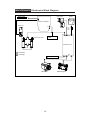
5. MECHANICAL ADJUSTMENTS
Designed to suit exercisers of different heights, the E850 elliptical trainer has an
adjustable stride length. To modify the stride length, pull the adjustment handle
toward yourself. Then lift the handle up or down to the desired position. Make sure
that the pin on the other side of the handle snaps into place, extending outward from
the hole in the vertical arm.

16
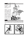
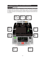
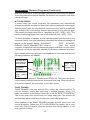
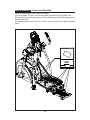
6. UNDERSTAND THE E850 DISPLAY
DISPLAY Overview
The E850 elliptical trainer is designed for user convenience. With better
feedback about your workout, you get better results. The following explains
the display key and window functions. Please read this manual, understand
the display functions, and thereby get optimum enjoyment and benefit from
this product.
Weight
loss target
heart rate
Actual
heart rate
Cardio
target
heart rate
Workout
program
keys
Resistance
level keys
Workout
illustration
window
Pulse
indicator
Workout
feedback
window
Feedback
row
control

17
DISPLAY Windows
● The 65% target heart rate window shows the optimum heart rate zone
for weight loss.
● The heart rate window shows actual heart rate.
● The 80% target heart rate window shows the optimim heart rate zone for
cardio conditioning.
● The workout illustration window shows workout illustrations and workout
prompts.
● The exercise feedback window shows workout prompts and information.
● LED indicators light to indicate active programs, scan mode, selection
conrmations, and heart rate.
DISPLAY Keys
CHANGE – Press the CHANGE key while exercising to view different workout
feedback. Active feedback indicators light up. Top row: WORKOUT LEVEL,
CALORIES, TIME, WATTS. Bottom row: DISTANCE, CAL/HR, STRIDES/MIN,
TOTAL STRIDES. In SCAN mode, a different row of feedback is displayed every
six seconds, and the scan indicator ashes every second. If not in scan mode, the
SCAN indicator will remain lit.
QUICK START – Press this key to start exercising without rst entering user infor-
mation such as age and weight. In QUICK START mode, time counts upward; time
values accumulate.
START – Press this key to start exercising after inputting user information.
WORKOUT PROGRAMS – When these indicators ash, or during a workout,
simply press any one of these keys to activate the corresponding workout program.
The workout’s associated LED will light to indicate its activation.
ENTER – After making a selection, press this key to conrm your choice.
▲/▼ -- Press ▲/▼ keys to set USER, AGE, WEIGHT, TIME and LEVEL
values.
STOP/HOLD TO RESET – This key has two functions--pause and reset--the
activation of which depends, in part, on how you began exercising. If you pressed
the QUICK START key to start your workout, press the STOP key to exit the current
workout. If you pressed the START key and began a workout, press the STOP
key to return to the “SELECT PROGRAM” prompt. Workout program indicators will
ash, prompting you to select a workout program. Under any circumstance, holding
the STOP key down for three seconds will allow you to leave the workout and return
to the startup banner screen.

18
DISPLAY Specications
WORKOUT LEVEL (resistance): 1 to 20
TIME: 00:00 to 99:59 (accumulated workout time or time remaining)
DISTANCE: 0.01-9999 km or mile
CALORIES: 0 to 9999 kcal (expenditure)
CAL/Hr: 0.0 - 999.9 kcal
STRIDES/MIN : 0 to 160 strides per minute
WATTS: 0 to 9999
TOTAL STRIDES : 0 to 9999
7. OPERATE THE E850 ELLIPTICAL TRAINER
There are three ways to activate the E850 elliptical trainer. (1) Press the QUICK
START key to start exercising without rst inputting user information such as age
and weight. (2) Press the START key to start exercising after inputting user infor-
mation such as age and weight. (3) Or simply start exercising at twenty or more
strides per minute. When activated, the display will light up, and the startup banner
screen “SPORTSART-E850” will appear.
QUICK START and START modes of operation are explained below.
OPERATION QUICK START Mode
Press the QUICK START key if you want to begin exercising immediately,
without first entering age and weight values.
QUICK START mode has the following characteristics:
In QUICK START mode, calorie and target heart rate values are calculated
based on the assumption that the exerciser is 35 years old and weighs 75 kg,
165 lb. Time counts upward. The resistance setting begins at level one and
can be changed at any time.
Workout programs, including ZONE TRAINER, can be activated at any
time. In workout programs activated via the QUICK START key, time counts
upward, and the resistance setting can be changed at any time.
If no one exercises on the product, the message “STEP TO START” will
scroll across the display every four seconds. If no one exercises on the
product for 15 seconds, a power saving mode will be activated. All lights
on the display will extinguish except for four flashing lines in the exercise
feedback window. If someone exercises at 20 strides per minute or faster,
lights on the display will appear again. If not, after two minutes, lights on the
display will extinguish.

19
OPERATION START Mode
Press the START key to take advantage of stored user information. User
age and weight values are used to calculate target heart rates and calorie
expenditures respectively. This provides more accurate target heart rate
and calorie expenditure values. And having user information saved in the
product’s memory allows you to view workout records. Each time that you
exercise your workout time, distance, and calorie expenditure values can
be automatically committed to the product’s memory. You can view this
information when you activate your user ID.
To establish a user ID, follow the instructions below.
1. At the startup banner screen (when “SPORTSART-E850” appears),
press the START key. The message window will show the previous user’s
ID and accumulated workout data. Every six seconds, one of the following
messages will appear:
USER - 1
TIME - 25:05
DIST - 15.8
CALS - 1020
Note: The values that appear on the product will probably differ from those
shown above.
Press ▲/▼ keys to select one of four user IDs (1, 2, 3, or 4). Then press the
ENTER key to confirm your choice.
2. Rather than having a user ID number, you can create your own user name
with up to 11 alphabetical characters. To do so, follow the instructions below.
(You can skip this step if desired.) While the user ID number appears, press
and hold the CHANGE key for three seconds. This activates the user name
setting mode. “ENTER NAME” will appear on the product display.
E N T E R N A M E
Press ▲/▼ keys to select alphabetical characters. When your preference
appears, press the ENTER key to confirm your choice. Use this method to
select up to 11 characters. When your user ID name has been completed,
hold the ENTER key for three seconds. The display will show the “USER ID”
prompt.

20
OPERATION START Mode (Continued)
To modify or delete a user ID name, complete the following procedure. As
the user name appears, hold the CHANGE key for three seconds. The user
name will disappear. Then create a new user name as explained above.
To delete user data (accumulated workout time, strides, and distance), while
the user ID appears, simultaneously press the STOP and START keys.
3. Follow instructions below to input user age and weight information. The
“AGE” prompt will appear on the display. The age setting range is 10 to
99 years with a default age of 35 years. Press ▲/▼ keys to select an age
value. The age value is used to calculate heart rate target values. Press the
ENTER key to confirm the age setting and proceed to the weight setting.
The “WEIGHT” prompt will appear on the display. The weight range is 30
to 180 kg, 66 to 400 lb., with a default value of 75 kg, 165 lb. Press ▲/▼
keys to select a weight value. The weight value is used to calculate calorie
expenditure. Press the ENTER key to confirm the weight setting and proceed
to the program setting.
4. Follow instructions below to select a workout program. Press the workout
program key of your choice. The workout program indicator LED will become
lit. Press the ENTER key to confirm your choice and procedd to the time
setting.
Note: The ZONE TRAINER program can only be activated via another
workout and after a heart rate value has been obtained.
5. Follow instructions below to establish the duration of your workout. Press
▲/▼ keys to select a time value. Then press the ENTER key to confirm the
time settting and begin the workout.
Workout programs have the following characteristics in common:
● When a workout is selected, its corresponding illustration appears on the
display. In the workout illustration, the ashing LED represents the exer-
ciser’s current position in the workout.
● If a different program is selected while time is counting upward, the time
value will continue to accrue from the new segment.
● If a different program is selected while time is counting down in a user
ID-activated program, values accumulate from that segment.
● Note that ZONE TRAINER differs from other programs. Refer to Pro-
grams below for information about that particular workout.
La page est en cours de chargement...
La page est en cours de chargement...
La page est en cours de chargement...
La page est en cours de chargement...
La page est en cours de chargement...
La page est en cours de chargement...
La page est en cours de chargement...
La page est en cours de chargement...
La page est en cours de chargement...
La page est en cours de chargement...
La page est en cours de chargement...
La page est en cours de chargement...
La page est en cours de chargement...
La page est en cours de chargement...
-
 1
1
-
 2
2
-
 3
3
-
 4
4
-
 5
5
-
 6
6
-
 7
7
-
 8
8
-
 9
9
-
 10
10
-
 11
11
-
 12
12
-
 13
13
-
 14
14
-
 15
15
-
 16
16
-
 17
17
-
 18
18
-
 19
19
-
 20
20
-
 21
21
-
 22
22
-
 23
23
-
 24
24
-
 25
25
-
 26
26
-
 27
27
-
 28
28
-
 29
29
-
 30
30
-
 31
31
-
 32
32
-
 33
33
-
 34
34


SportsArt Fitness E850 Le manuel du propriétaire
- Taper
- Le manuel du propriétaire
dans d''autres langues
Documents connexes
Autres documents
-
SportsArt G862 Le manuel du propriétaire
-
-
-
-
-
-
-
-
-