Panasonic ey 7450 ln2s Le manuel du propriétaire
- Catégorie
- Perceuses mixtes sans fil
- Taper
- Le manuel du propriétaire

-
1
-
-
1
-
Operating Instructions
Bedienungsanleitung
Instructions d’utilisation
Istruzioni per l’uso
Gebruiksaanwijzing
Manual de instrucciones
Brugsvejledning
Driftsföreskrifter
Bruksanvisning
Käyttöohjeet
Before operating this unit, please read these instructions completely and save this manual for future use.
Vor Inbetriebnahme des Gerätes die Betriebsanleitung bitte gründlich durchlesen und diese Broschüre zum späteren Nachschlagen
sorgfältig aufbewahren.
Lire entièrement les instructions suivantes avant de faire fonctionner l’appareil et conserver ce mode d’emploi à des fins de consultation
ultérieure.
Prima di usare questa unità, leggere completamente queste istruzioni e conservare il manuale per usi futuri.
Lees deze gebruiksaanwijzing aandachtig door voor u het apparaat in gebruik neemt en bewaar de gebruiksaanwijzing voor eventuele
naslag.
Antes de usar este aparato por primera vez, lea todas las instrucciones de este manual y guarde el manual para poderlo consultar en el
futuro.
Gennemlæs denne betjeningsvejledning før brugen og gem den til fremtidig brug.
Läs igenom hela bruksanvisningen innan verktyget tas i bruk. Spara bruksanvisningen för senare användning.
Før enheten tas i bruk, vennligst les disse alle anvisningene og oppbevar deretter bruksanvisningen for senere bruk.
Lue ohjeet huolella ennen laitteen käyttöönottoa ja säilytä tämä käyttöohje tallessa tulevaa tarvetta varten.
Cordless Drill & Driver/Cordless Hammer Drill & Drive
r
Akku-Bohrschrauber/Akku-Schlagbohrschraube
r
Perceuse-visseuse sans fil/Perceuse à percussion-visseuse sans fil
Trapano avvitatore cordless/Trapano avvitatore cordless a percussione
Snoerloze schroef-boormachine/Snoerloze slagschroef-boormachine
Destornillador y taladro sin cables/Destornillador y taladro percutor sin cables
Akku bor & skruetrækker/Akku hammerbor & skruertrække
r
Sladdlös skruvdragare & borrmaskin/slagborrmaskin
Ledningløs drill og skrutrekker/Ledningløs slagdrill og skrutrekke
r
Ladattava pora & ruuvinväännin/ladattava vasaraporapora & ruuvinväännin
Model No: EY7442/EY7450/EY7950
EY7442_7450_7950(EU).indb 1 2011-3-1 11:33:56

-
2
-
Index/Index/Index/Indice/Index/Indice/Indeks/Index/Indeks/Hakemisto
English: Page 5
Deutsch: Seite 17
Français: Page 28
Italiano: Pagina 39
Nederlands: Bladzijde 49
Español: Página 60
Dansk: Side 71
Svenska: Sid 81
Norsk: Side 91
Suomi: Sivu 101
FUNCTIONAL DESCRIPTION
FUNKTIONSBESCHREIBUNG
DESCRIPTION DES FONCTIONS
DESCRIZIONE DELLE FUNZIONI
FUNCTIEBESCHRIJVING
DESCRIPCIÓN FUNCIONAL
FUNKTIONSBESKRIVELSE
FUNKTIONSBESKRIVNING
FUNKSJONSBESKRIVELSE
TOIMINTAKUVAUS
(O)
(P)
(E)
(N)
(E)
(F)
(G)
(I)
(J)
(
K)
(A)
(B)
(C)
(M)
(D)
(L)
(H)
(K)
(A)
Keyless drill chuck
Schlüsselfreies Bohrfutter
Mandrin porte-foret sans fil
Mandrino autoserrante
Boorkop zonder sleutel
Mandril sin llave
Nøglefri borepatron
Nyckellös borrchuck
Nøkkelfri drillchuck
Avaimeton poran kiinnityslaite
(B)
Clutch handle
Kupplungsring
Poignée de l’embrayage
Impugnatura frizione
Koppelingshandgreep
Mango de embrague
Koblinghåndtag
Kopplingshandtag
Koblingshåndtak
Kytkimen kahva
(C)
Speed selector switch
Bereichsschalter
Interrupteur de sélection de vitesse
Regolatore di velocità
Snelheidskeuzeschakelaar
Interruptor selector de velocidad
Hastighedsvælger
Hastighetsomkopplare
Hastighetskontroll
Nopeuden valintakytkin
(D)
Forward/Reverse lever
Rechts/Linkslauf Schalter
Levier d’inversion marche avant-marche arrière
Leva di avanzamento/inversione
Voorwaarts/achterwaarts-hendel
Palanca de avance/inversión
Greb til forlæns/baglæns retning
Riktningsomkopplare
Forover/Revers bryter
Eteenpäin/taaksepäin vipu
(E)
Alignment marks
Ausrichtmarkierungen
Marques d’alignement
Marcature allineamento
Uitlijntekens
Marcas de alineación
Flugtemærker
Anpassningsmärken
Opprettingsmerke
Sovitusmerkit
(F)
Battery pack release button
Akku-Entriegelungsknopf
Bouton de libération de batterie autonome
Tasto di rilascio pacco batteria
Accu-ontgrendeltoets
Botón de liberación de batería
Udløserknap til batteripakning
Frigöringsknapp för batteri
Utløserknapp for batteripakke
Akkupaketin irrotuspainike
(G)
Battery pack
Akku
Batterie autonome
Pacco batteria
Accu
Batería
Batteripakning
Batteri
Batteripakke
Akku
(H)
Control panel
Bedienfeld
Panneau de commande
Pannello di controllo
Bedieningspaneel
Panel de controle
Kontrolpanel
Kontrollpanel
Kontrollpanel
Säätöpaneeli
(I)
Overheat warning lamp
Überhitzungs-Warnlampe
Témoin d’avertissement de surchauffe
Spia avvertenza surriscaldamento
Oververhitting-waarschuwingslampje
Luz de advertencia de sobrecalentamiento
Advarselslamp til overophedning
Varningslampa för överhettning
Varsellampe for overoppheting
Ylikuumenemisen varoituslamppu
(J)
LED light on/off button
LED-Leuchten-EIN/AUS-Taste
Bouton Marche/Arrêt de la lumière DEL
Tasto di accensione e spegnimento della luce LED
Aan/uit-toets (ON/OFF) voor LED-lampje
Botón ON/OFF de luz LED
TÆND/SLUK-knap til LED-lys
Strömbrytare för LED-ljus
PÅ/AV-knapp for LED-lys
LED-valon kytkin/katkaisupainike
(K)
LED light
LED-Leuchte
Lumière DEL
Luce LED
LED-lampje
Luz indicadora
LED-lys
LED-ljus
LED-lys
LED-valo
(L)
Battery low warning lamp
Akkuladungs-Warnlampe
Témoin d’avertissement de batterie basse
Spia avvertenza batteria scarica
Waarschuwingslampje voor lage accuspanning
Luz de aviso de baja carga de batería
Advarselslampes batterieffekt lav
Varningslampa för svagt batteri
Varsellampe for at batteriet er for lavt
Alhaisen akkujännitteen varoituslamppu
EY7442_7450_7950(EU).indb 2 2011-3-1 11:33:56

-
3
-
Index/Index/Index/Indice/Index/Indice/Indeks/Index/Indeks/Hakemisto
English: Page 5
Deutsch: Seite 17
Français: Page 28
Italiano: Pagina 39
Nederlands: Bladzijde 49
Español: Página 60
Dansk: Side 71
Svenska: Sid 81
Norsk: Side 91
Suomi: Sivu 101
FUNCTIONAL DESCRIPTION
FUNKTIONSBESCHREIBUNG
DESCRIPTION DES FONCTIONS
DESCRIZIONE DELLE FUNZIONI
FUNCTIEBESCHRIJVING
DESCRIPCIÓN FUNCIONAL
FUNKTIONSBESKRIVELSE
FUNKTIONSBESKRIVNING
FUNKSJONSBESKRIVELSE
TOIMINTAKUVAUS
(O)
(P)
(E)
(N)
(E)
(F)
(G)
(I)
(J)
(
K)
(A)
(B)
(C)
(M)
(D)
(L)
(H)
(K)
(A)
Keyless drill chuck
Schlüsselfreies Bohrfutter
Mandrin porte-foret sans fil
Mandrino autoserrante
Boorkop zonder sleutel
Mandril sin llave
Nøglefri borepatron
Nyckellös borrchuck
Nøkkelfri drillchuck
Avaimeton poran kiinnityslaite
(B)
Clutch handle
Kupplungsring
Poignée de l’embrayage
Impugnatura frizione
Koppelingshandgreep
Mango de embrague
Koblinghåndtag
Kopplingshandtag
Koblingshåndtak
Kytkimen kahva
(C)
Speed selector switch
Bereichsschalter
Interrupteur de sélection de vitesse
Regolatore di velocità
Snelheidskeuzeschakelaar
Interruptor selector de velocidad
Hastighedsvælger
Hastighetsomkopplare
Hastighetskontroll
Nopeuden valintakytkin
(D)
Forward/Reverse lever
Rechts/Linkslauf Schalter
Levier d’inversion marche avant-marche arrière
Leva di avanzamento/inversione
Voorwaarts/achterwaarts-hendel
Palanca de avance/inversión
Greb til forlæns/baglæns retning
Riktningsomkopplare
Forover/Revers bryter
Eteenpäin/taaksepäin vipu
(E)
Alignment marks
Ausrichtmarkierungen
Marques d’alignement
Marcature allineamento
Uitlijntekens
Marcas de alineación
Flugtemærker
Anpassningsmärken
Opprettingsmerke
Sovitusmerkit
(F)
Battery pack release button
Akku-Entriegelungsknopf
Bouton de libération de batterie autonome
Tasto di rilascio pacco batteria
Accu-ontgrendeltoets
Botón de liberación de batería
Udløserknap til batteripakning
Frigöringsknapp för batteri
Utløserknapp for batteripakke
Akkupaketin irrotuspainike
(G)
Battery pack
Akku
Batterie autonome
Pacco batteria
Accu
Batería
Batteripakning
Batteri
Batteripakke
Akku
(H)
Control panel
Bedienfeld
Panneau de commande
Pannello di controllo
Bedieningspaneel
Panel de controle
Kontrolpanel
Kontrollpanel
Kontrollpanel
Säätöpaneeli
(I)
Overheat warning lamp
Überhitzungs-Warnlampe
Témoin d’avertissement de surchauffe
Spia avvertenza surriscaldamento
Oververhitting-waarschuwingslampje
Luz de advertencia de sobrecalentamiento
Advarselslamp til overophedning
Varningslampa för överhettning
Varsellampe for overoppheting
Ylikuumenemisen varoituslamppu
(J)
LED light on/off button
LED-Leuchten-EIN/AUS-Taste
Bouton Marche/Arrêt de la lumière DEL
Tasto di accensione e spegnimento della luce LED
Aan/uit-toets (ON/OFF) voor LED-lampje
Botón ON/OFF de luz LED
TÆND/SLUK-knap til LED-lys
Strömbrytare för LED-ljus
PÅ/AV-knapp for LED-lys
LED-valon kytkin/katkaisupainike
(K)
LED light
LED-Leuchte
Lumière DEL
Luce LED
LED-lampje
Luz indicadora
LED-lys
LED-ljus
LED-lys
LED-valo
(L)
Battery low warning lamp
Akkuladungs-Warnlampe
Témoin d’avertissement de batterie basse
Spia avvertenza batteria scarica
Waarschuwingslampje voor lage accuspanning
Luz de aviso de baja carga de batería
Advarselslampes batterieffekt lav
Varningslampa för svagt batteri
Varsellampe for at batteriet er for lavt
Alhaisen akkujännitteen varoituslamppu
EY7442_7450_7950(EU).indb 3 2011-3-1 11:33:56

-
4
-
(M)
Variable speed control trigger
Betriebsschalter
Gâchette de commande de vitesse
Grilletto di controllo velocità variable
Startschakelaar variabele snelheid
Disparador del control de velocided variable
Kontroludløser for variabel hastighed
Steglös varvtalsreglerare
Hovedbryter, trinnløs
Nopeudensäätökytkin
(N)
Support handle
Zusatzgriff
Manche de support
Maniglia di sostegno
Steungreep
Mango de soporte
Hjælpehåndtag
Stödhandtag
Støttehåndtak
Tukikahva
(O)
Battery charger
Ladegerät
Chargeur de batterie
Caricabatterie
Acculader
Cargador de batería
Batterioplader
Batteriladdare
Batterilader
Akkulaturi
(P)
Battery pack cover
Akkuabdeckung
Couvercle de la batterie autonome
Coperchio pacco batteria
Accudeksel
Cubierta de batería
Akkuafdækning
Batterilock
Batteripakkedeksel
Akun kansi
Original instructions: English
Translation of the original instructions:
Other languages
This tool, as a complete unit with a battery pack,
satisfies appropriate IP Degrees of Protection
based on the IEC regulations.
Definition of IP code
IP5X: Ingress of dust is not totally prevented,
but dust shall not penetrate in a quantity to
interfere with satisfactory operation of the tool
or to impair safety (In case that the talcum
powder under 75 μm intrudes inside the tool)
IPX6: Water projected in powerful jets against
the tool from any direction shall have no
harmful effects (In case that, with a nozzle
of 12.5 mm inner diameter, approximately
100 L/min of normal temperature water is
injected to the tool for 3 minutes from 3 meter
distance)
LIMITED WARRANTY
The rating of IP56 qualifies this tool for the
minimum impact of water or dust, but not for
the assurance of performance in such condi-
tions. See Safety and Operating Instructions
for further details for proper operation.
Read “the Safety Instructions” booklet
and the following before using.
I. INTENDED USE
These tools can be used to tighten
screws in clutch mode and to drill
holes in wood and metal in drill
mode. Additionally, model EY7950
can be used to drill holes in soft
concrete and similar materials in
hammer mode.
Read the Safety Instructions booklet
and the following before using.
II. ADDITIONAL
SAFETY RULES
1)
Wear ear protectors.
Exposure to noise can cause
hearing loss.
2)
Use auxiliary handle supplied
with the tool.
Loss of control can cause personal
injury.
3)
Hold power tools by insulated
gripping surfaces when per-
forming an operation where the
cutting tool may contact hidden
wiring
; contact with a “live” wire will
make exposed metal parts of the
tool “live” and shock the operator.
4) Wear a dust mask, if the work
causes dust.
5) Be aware that this tool is always in
an operating condition, since it
does not have to be plugged into
an electrical outlet.
6) When drilling or driving into walls,
floors, etc., "live" electrical wires
may be encountered. DO NOT
TOUCH THE CHUCK OR ANY
FRONT METAL PARTS OF THE
TOOL! Hold the tool only by the
plastic handle to prevent electric
shock in case you drill or drive into
a "live" wire.
7) If the bit becomes jammed, im-
mediately turn the trigger switch
off to prevent an overload, which
can damage the battery pack or
motor.
Use reverse motion to loosen
jammed bits.
8) Do NOT operate the For-
ward/Reverse lever when the
trigger switch is on. The battery
will discharge rapidly and dam-
age to the unit may occur.
9) During charging, the charger
may become slightly warm. This
is normal. Do NOT charge the
battery for a long period.
EY7442_7450_7950(EU).indb 4 2011-3-1 11:33:56

-
5
-
(M)
Variable speed control trigger
Betriebsschalter
Gâchette de commande de vitesse
Grilletto di controllo velocità variable
Startschakelaar variabele snelheid
Disparador del control de velocided variable
Kontroludløser for variabel hastighed
Steglös varvtalsreglerare
Hovedbryter, trinnløs
Nopeudensäätökytkin
(N)
Support handle
Zusatzgriff
Manche de support
Maniglia di sostegno
Steungreep
Mango de soporte
Hjælpehåndtag
Stödhandtag
Støttehåndtak
Tukikahva
(O)
Battery charger
Ladegerät
Chargeur de batterie
Caricabatterie
Acculader
Cargador de batería
Batterioplader
Batteriladdare
Batterilader
Akkulaturi
(P)
Battery pack cover
Akkuabdeckung
Couvercle de la batterie autonome
Coperchio pacco batteria
Accudeksel
Cubierta de batería
Akkuafdækning
Batterilock
Batteripakkedeksel
Akun kansi
Original instructions: English
Translation of the original instructions:
Other languages
This tool, as a complete unit with a battery pack,
satisfies appropriate IP Degrees of Protection
based on the IEC regulations.
Definition of IP code
IP5X: Ingress of dust is not totally prevented,
but dust shall not penetrate in a quantity to
interfere with satisfactory operation of the tool
or to impair safety (In case that the talcum
powder under 75 μm intrudes inside the tool)
IPX6: Water projected in powerful jets against
the tool from any direction shall have no
harmful effects (In case that, with a nozzle
of 12.5 mm inner diameter, approximately
100 L/min of normal temperature water is
injected to the tool for 3 minutes from 3 meter
distance)
LIMITED WARRANTY
The rating of IP56 qualifies this tool for the
minimum impact of water or dust, but not for
the assurance of performance in such condi-
tions. See Safety and Operating Instructions
for further details for proper operation.
Read “the Safety Instructions” booklet
and the following before using.
I. INTENDED USE
These tools can be used to tighten
screws in clutch mode and to drill
holes in wood and metal in drill
mode. Additionally, model EY7950
can be used to drill holes in soft
concrete and similar materials in
hammer mode.
Read the Safety Instructions booklet
and the following before using.
II. ADDITIONAL
SAFETY RULES
1)
Wear ear protectors.
Exposure to noise can cause
hearing loss.
2)
Use auxiliary handle supplied
with the tool.
Loss of control can cause personal
injury.
3)
Hold power tools by insulated
gripping surfaces when per-
forming an operation where the
cutting tool may contact hidden
wiring
; contact with a “live” wire will
make exposed metal parts of the
tool “live” and shock the operator.
4) Wear a dust mask, if the work
causes dust.
5) Be aware that this tool is always in
an operating condition, since it
does not have to be plugged into
an electrical outlet.
6) When drilling or driving into walls,
floors, etc., "live" electrical wires
may be encountered. DO NOT
TOUCH THE CHUCK OR ANY
FRONT METAL PARTS OF THE
TOOL! Hold the tool only by the
plastic handle to prevent electric
shock in case you drill or drive into
a "live" wire.
7) If the bit becomes jammed, im-
mediately turn the trigger switch
off to prevent an overload, which
can damage the battery pack or
motor.
Use reverse motion to loosen
jammed bits.
8) Do NOT operate the For-
ward/Reverse lever when the
trigger switch is on. The battery
will discharge rapidly and dam-
age to the unit may occur.
9) During charging, the charger
may become slightly warm. This
is normal. Do NOT charge the
battery for a long period.
EY7442_7450_7950(EU).indb 5 2011-3-1 11:33:56

-
6
-
10) When storing or carrying the tool,
set the Forward/Reverse lever to
the center position (switch lock).
11) Do not strain the tool by holding the
speed control trigger halfway
(speed control mode) so that the
motor stops.
12) Do not operate the speed selector
switch (LOW-HIGH) while pulling
on the speed control trigger. This
can cause the rechargeable battery
to wear quickly or damage the in-
ternal mechanism of the motor.
Symbol Meaning
V Volts
Direct current
n
0
No load speed
…min
-1
Revolutions or recip-
rocations per minutes
Ah
Electrical capacity of
battery pack
Forward rotation
Reverse rotation
Rotation with ham-
mering
Rotation only
To reduce the risk of
injury, user must read
and understand in-
struction manual.
For indoor use only.
WARNING:
• Do not use other than the Pana-
sonic battery packs that are de-
signed for use with this recharge-
able tool.
• Panasonic is not responsible for
any damage or accident caused by
the use of the recycled battery pack
and the counterfeit battery pack.
• Do not dispose of the battery pack
in a fire, or expose it to excessive
heat.
• Do not drive the likes of nails into
the battery pack, subject it to
shocks, dismantle it, or attempt to
modify it.
• Do not allow metal objects to touch
the battery pack terminals.
• Do not carry or store the battery
pack in the same container as nails
or similar metal objects.
• Do not charge the battery pack in a
high-temperature location, such as
next to a fire or in direct sunlight.
Otherwise, the battery may over-
heat, catch fire, or explode.
• Never use other than the dedicated
charger to charge the battery pack.
Otherwise, the battery may leak,
overheat, or explode.
• After removing the battery pack
from the tool or the charger, always
reattach the pack cover. Otherwise,
the battery contacts could be
shorted, leading to a risk of fire.
• When the Battery Pack Has Dete-
riorated, Replace It with a New
One.
Continued use of a damaged bat-
tery pack may result in heat gen-
eration, ignition or battery rupture.
III. ASSEMBLY
Attaching or Removing Bit
NOTE:
When attaching or removing a bit,
disconnect battery pack from tool or
place the switch in the center position
(switch lock).
This tool is equipped with a keyless
drill chuck.
1. Attachment
Insert the bit and turn the lock collar
clockwise (looking from the front) to
tighten firmly until it stops clicking.
Lock collar
2. Removal
Turn the lock collar counterclock-
wise (looking from the front), then
remove the bit.
NOTE:
If excessive play occurs in the chuck,
secure the drill in place and
open the chuck jaws by turning the
lock collar and
tighten the screw
(left-handed screw) with a screw-
driver by turning it counterclockwise
(viewed from the front).
Attaching or Removing Bat-
tery Pack
1. To connect the battery pack:
Line up the alignment marks and at-
tach the battery pack.
• Slide the battery pack until it locks
into position.
2. To remove the battery pack:
Pull the button from the front to re-
lease the battery pack.
Support handle
Place the support handle at your fa-
vorite position and tighten the handle
securely.
Always use the support handle to
ensure operating safety.
Button
A
lignment marks
Tighten
Loosen
EY7442_7450_7950(EU).indb 6 2011-3-1 11:33:57

-
7
-
10) When storing or carrying the tool,
set the Forward/Reverse lever to
the center position (switch lock).
11) Do not strain the tool by holding the
speed control trigger halfway
(speed control mode) so that the
motor stops.
12) Do not operate the speed selector
switch (LOW-HIGH) while pulling
on the speed control trigger. This
can cause the rechargeable battery
to wear quickly or damage the in-
ternal mechanism of the motor.
Symbol Meaning
V Volts
Direct current
n
0
No load speed
…min
-1
Revolutions or recip-
rocations per minutes
Ah
Electrical capacity of
battery pack
Forward rotation
Reverse rotation
Rotation with ham-
mering
Rotation only
To reduce the risk of
injury, user must read
and understand in-
struction manual.
For indoor use only.
WARNING:
• Do not use other than the Pana-
sonic battery packs that are de-
signed for use with this recharge-
able tool.
• Panasonic is not responsible for
any damage or accident caused by
the use of the recycled battery pack
and the counterfeit battery pack.
• Do not dispose of the battery pack
in a fire, or expose it to excessive
heat.
• Do not drive the likes of nails into
the battery pack, subject it to
shocks, dismantle it, or attempt to
modify it.
• Do not allow metal objects to touch
the battery pack terminals.
• Do not carry or store the battery
pack in the same container as nails
or similar metal objects.
• Do not charge the battery pack in a
high-temperature location, such as
next to a fire or in direct sunlight.
Otherwise, the battery may over-
heat, catch fire, or explode.
• Never use other than the dedicated
charger to charge the battery pack.
Otherwise, the battery may leak,
overheat, or explode.
• After removing the battery pack
from the tool or the charger, always
reattach the pack cover. Otherwise,
the battery contacts could be
shorted, leading to a risk of fire.
• When the Battery Pack Has Dete-
riorated, Replace It with a New
One.
Continued use of a damaged bat-
tery pack may result in heat gen-
eration, ignition or battery rupture.
III. ASSEMBLY
Attaching or Removing Bit
NOTE:
When attaching or removing a bit,
disconnect battery pack from tool or
place the switch in the center position
(switch lock).
This tool is equipped with a keyless
drill chuck.
1. Attachment
Insert the bit and turn the lock collar
clockwise (looking from the front) to
tighten firmly until it stops clicking.
Lock collar
2. Removal
Turn the lock collar counterclock-
wise (looking from the front), then
remove the bit.
NOTE:
If excessive play occurs in the chuck,
secure the drill in place and
open the chuck jaws by turning the
lock collar and
tighten the screw
(left-handed screw) with a screw-
driver by turning it counterclockwise
(viewed from the front).
Attaching or Removing Bat-
tery Pack
1. To connect the battery pack:
Line up the alignment marks and at-
tach the battery pack.
• Slide the battery pack until it locks
into position.
2. To remove the battery pack:
Pull the button from the front to re-
lease the battery pack.
Support handle
Place the support handle at your fa-
vorite position and tighten the handle
securely.
Always use the support handle to
ensure operating safety.
Button
A
lignment marks
Tighten
Loosen
EY7442_7450_7950(EU).indb 7 2011-3-1 11:33:57

-
8
-
IV. OPERATION
[Main Body]
Switch Operation
1. The speed increases with the
amount of depression of the trigger.
When beginning work, depress the
trigger slightly to start the rotation
slowly.
2. A feedback electronic controller is
used to give a strong torque even in
low speed.
3. The brake operates when the trig-
ger is released and the motor stops
immediately.
NOTE:
• When the brake operates, a braking
sound may be heard. This is normal.
• Sparks from the motor brush may be
visible through the body vent holes
on the back of the tool during
switching and braking due to the
load imposed on the motor. This
does not indicate a problem with the
tool.
Switch and Forward/Reverse
Lever Operation
Forward Reverse
Switch lock
CAUTION:
To prevent damage, do not operate
Forward/Reverse lever until the bit
comes to a complete stop.
Forward Rotation Switch Op-
eration
1. Push the lever for forward rotation.
2. Depress the trigger switch slightly
to start the tool slowly.
3. The speed increases with the
amount of depression of the trigger
for efficient tightening of screws
and drilling. The brake operates
and the chuck stops immediately
when the trigger is released.
4. After use, set the lever to its center
position (switch lock).
Reverse Rotation Switch Op-
eration
1. Push the lever for reverse rotation.
Check the direction of rotation be-
fore use.
2. Depress the trigger switch slightly
to start the tool slowly.
3. After use, set the lever to its center
position (switch lock).
Clutch Torque Setting
Adjust the torque to one of the 18
clutch settings or "
" position
(EY7442, EY7450).
Adjust the torque to one of the 18
clutch settings or "
", " " position
(EY7950).
NOTE:
Always make sure to stop opera-
tion of the tool and disengage it
from the work, when you select
Hammering mode from Drilling
mode or when you shift to Drilling
mode from Hammering mode by
rotating clutch handle.
LOW
HIGH
CAUTION:
If the clutch handle cannot be set at
“drilling” or “hammering” mode after
drilling with clutch function, set the
clutch handle at position 1 and oper-
ate the clutch for a second.
Speed Selection
Choose a low or high speed to suit
the use.
The more the variable speed control
trigger is pulled, the higher the speed
becomes.
WARNING:
• Do not inhale any smoke emitted
from the tool or battery pack as it
may be harmful.
CAUTION:
• Check the speed selector switch
before use.
•
Use at low speed when high torque
is needed during operation. (Using
at high speed when high torque is
required may cause a motor
breakdown.)
•
Do not use the tool in a manner
that causes the motor to lock up.
Doing so may damage the tool and
battery pack, resulting in smoke or
fire.
•
Do not operate the speed selector
switch (LOW-HIGH) while pulling
on the speed control trigger. This
can cause the rechargeable battery
to wear quickly or damage the in-
ternal mechanism of the motor.
* See specifications for "MAXIMUM
RECOMMENDED CAPACITIES".
CAUTION:
• To prevent excessive temperature in-
crease of the tool surface, do not op-
erate the tool continuously using two
or more battery packs. The tool needs
cool-off time before switching to an-
other pack.
• Do not close up vent holes on the
sides of the body during operation.
Otherwise, the machine function is
adversely affected to cause a failure.
• Do NOT strain the tool (motor). This
may cause damage to the unit.
• Use the tool in such a way as to pre-
vent the air from the body vent holes
from blowing directly onto your skin.
Otherwise, you may get burned.
Bit-locking Function
1. With the trigger switch not engaged
and a screwdriver bit locked in
place, the tool can be used as a
manual screwdriver.
(EY7442: up to 36 N·m, 367kgf-cm, 319 in-lbs)
(EY7450, 7950: up to 40 N·m, 408kgf-cm,
353 in-lbs)
There will be a little play in the
chuck, but this is not a malfunction.
2. This feature is handy for tightening
screws that require more torque
than the maximum torque of the
driver (position on the clutch), for
confirming the tightness of a screw
or to loosen an extremely tight
screw.
Control Panel
(1)
(3)
(2)
Set the clutch setting at this mark ( )
before actual operation.
EY7442_7450_7950(EU).indb 8 2011-3-1 11:33:57

-
9
-
IV. OPERATION
[Main Body]
Switch Operation
1. The speed increases with the
amount of depression of the trigger.
When beginning work, depress the
trigger slightly to start the rotation
slowly.
2. A feedback electronic controller is
used to give a strong torque even in
low speed.
3. The brake operates when the trig-
ger is released and the motor stops
immediately.
NOTE:
• When the brake operates, a braking
sound may be heard. This is normal.
• Sparks from the motor brush may be
visible through the body vent holes
on the back of the tool during
switching and braking due to the
load imposed on the motor. This
does not indicate a problem with the
tool.
Switch and Forward/Reverse
Lever Operation
Forward Reverse
Switch lock
CAUTION:
To prevent damage, do not operate
Forward/Reverse lever until the bit
comes to a complete stop.
Forward Rotation Switch Op-
eration
1. Push the lever for forward rotation.
2. Depress the trigger switch slightly
to start the tool slowly.
3. The speed increases with the
amount of depression of the trigger
for efficient tightening of screws
and drilling. The brake operates
and the chuck stops immediately
when the trigger is released.
4. After use, set the lever to its center
position (switch lock).
Reverse Rotation Switch Op-
eration
1. Push the lever for reverse rotation.
Check the direction of rotation be-
fore use.
2. Depress the trigger switch slightly
to start the tool slowly.
3. After use, set the lever to its center
position (switch lock).
Clutch Torque Setting
Adjust the torque to one of the 18
clutch settings or "
" position
(EY7442, EY7450).
Adjust the torque to one of the 18
clutch settings or "
", " " position
(EY7950).
NOTE:
Always make sure to stop opera-
tion of the tool and disengage it
from the work, when you select
Hammering mode from Drilling
mode or when you shift to Drilling
mode from Hammering mode by
rotating clutch handle.
LOW
HIGH
CAUTION:
If the clutch handle cannot be set at
“drilling” or “hammering” mode after
drilling with clutch function, set the
clutch handle at position 1 and oper-
ate the clutch for a second.
Speed Selection
Choose a low or high speed to suit
the use.
The more the variable speed control
trigger is pulled, the higher the speed
becomes.
WARNING:
• Do not inhale any smoke emitted
from the tool or battery pack as it
may be harmful.
CAUTION:
• Check the speed selector switch
before use.
•
Use at low speed when high torque
is needed during operation. (Using
at high speed when high torque is
required may cause a motor
breakdown.)
•
Do not use the tool in a manner
that causes the motor to lock up.
Doing so may damage the tool and
battery pack, resulting in smoke or
fire.
•
Do not operate the speed selector
switch (LOW-HIGH) while pulling
on the speed control trigger. This
can cause the rechargeable battery
to wear quickly or damage the in-
ternal mechanism of the motor.
* See specifications for "MAXIMUM
RECOMMENDED CAPACITIES".
CAUTION:
• To prevent excessive temperature in-
crease of the tool surface, do not op-
erate the tool continuously using two
or more battery packs. The tool needs
cool-off time before switching to an-
other pack.
• Do not close up vent holes on the
sides of the body during operation.
Otherwise, the machine function is
adversely affected to cause a failure.
• Do NOT strain the tool (motor). This
may cause damage to the unit.
• Use the tool in such a way as to pre-
vent the air from the body vent holes
from blowing directly onto your skin.
Otherwise, you may get burned.
Bit-locking Function
1. With the trigger switch not engaged
and a screwdriver bit locked in
place, the tool can be used as a
manual screwdriver.
(EY7442: up to 36 N·m, 367kgf-cm, 319 in-lbs)
(EY7450, 7950: up to 40 N·m, 408kgf-cm,
353 in-lbs)
There will be a little play in the
chuck, but this is not a malfunction.
2. This feature is handy for tightening
screws that require more torque
than the maximum torque of the
driver (position on the clutch), for
confirming the tightness of a screw
or to loosen an extremely tight
screw.
Control Panel
(1)
(3)
(2)
Set the clutch setting at this mark ( )
before actual operation.
EY7442_7450_7950(EU).indb 9 2011-3-1 11:33:57

-
10
-
(1) LED light
CAUTION:
• The built-in LED light is designed to
illuminate the small work area tempo-
rarily.
• Do not use it as a substitute for a reg-
ular flashlight, since it does not have
enough brightness.
• LED light turns off when the tool has
not been used for 5 minutes.
Caution: DO NOT STARE INTO BEAM.
Use of controls or adjustments or
performance of procedures other than
those specified herein may result in
hazardous radiation exposure.
(2) Overheat warning lamp
To protect the motor or battery, be
sure to note the following when car-
rying out this operation.
• If the motor or battery becomes hot,
the protection function will be acti-
vated and the motor or battery will
stop operating. The overheat warn-
ing lamp on the control panel illumi-
nates or flashes when this feature is
active.
• If the overheating protection feature
activates, allow the tool to cool tho-
roughly (at least 30 minutes). The
tool is ready for use when the over-
heat warning lamp goes out.
• Avoid using the tool in a way that
causes the overheating protection
feature to activate repeatedly.
• If the tool is operated continuously
under high-load conditions or if it is
used in hot-temperature conditions
(such as during summer), the over-
heating protection feature may acti-
vate frequently.
• If the tool is used in cold-temperature
conditions (such as during winter) or
if it is frequently stopped during use,
the overheating protection feature
may not activate.
• The performance of the EY9L42 de-
teriorates significantly at and below
10°C due to work conditions and
other factors.
(3) Battery low warning lamp
Excessive (complete) discharging of
lithium ion batteries shortens their
service life dramatically. The driver
includes a battery protection feature
designed to prevent excessive dis-
charging of the battery pack.
• The battery protection feature acti-
vates immediately before the battery
loses its charge, causing the battery
low warning lamp to flash.
• If you notice the battery low warning
lamp flashing, charge the battery
pack immediately.
Off
(normal
operation)
Flashing
(No charge)
Battery protection
feature active
Off
(normal
operation)
Flashing:
Overheat
(battery)
Indicates operation has
been halted due to motor
or battery overheating.
Before the use of LED light,
always pull the power switch
once.
Press the LED light
button.
The light illuminates with
very low current, and it does
not adversely affect the
performance of the tool
during use or its battery
capacity.
[Battery Pack]
For Appropriate Use of
Battery pack
Li-ion Battery pack
• For optimum battery life, store the
Li-ion battery pack following use
without charging it.
• When charging the battery pack,
confirm that the terminals on the
battery charger are free of foreign
substances such as dust and water
etc. Clean the terminals before
charging the battery pack if any for-
eign substances are found on the
terminals.
The life of the battery pack terminals
may be affected by foreign sub-
stances such as dust and water etc.
during operation.
• When battery pack is not in use,
keep it away from other metal ob-
jects like: paper clips, coins, keys,
nails, screws, or other small metal
objects that can make a connection
from one terminal to another.
Shorting the battery terminals to-
gether may cause sparks, burns or a
fire.
• When operating the battery pack,
make sure the work place is well
ventilated.
• When the battery pack is removed
from the main body of the tool, re-
place the battery pack cover imme-
diately in order to prevent dust or dirt
from contaminating the battery ter-
minals and causing a short circuit.
Battery Pack Life
The rechargeable batteries have a
limited life. If the operation time be-
comes extremely short after re-
charging, replace the battery pack
with a new one.
Battery Recycling
ATTENTION:
For environmental protection and
recycling of materials, be sure that
it is disposed of at an officially as-
signed location, if there is one in
your country.
[Battery Charger]
Charging
Cautions
• If the temperature of the battery pack
falls approximately below í10°C
(14°F), charging will automatically
stop to prevent degradation of the
battery.
• The ambient temperature range is
between 0°C (32°F) and 40°C (104°F).
If the battery pack is used when the
battery temperature is below 0°C (32°F),
the tool may fail to function properly.
• When charging a cool battery pack
(below 0°C (32°F)) in a warm place,
leave the battery pack at the place
and wait for more than one hour to
warm up the battery to the level of
the ambient temperature.
• Cool down the charger when charg-
ing more than two battery packs
consecutively.
• Do not insert your fingers into con-
tact hole, when holding charger or
any other occasions.
To prevent the risk of fire or damage to
the battery charger.
• Do not use power source from an en-
gine generator.
• Do not cover vent holes on the charger
and the battery pack.
• Unplug the charger when not in use.
EY7442_7450_7950(EU).indb 10 2011-3-1 11:33:58

-
11
-
(1) LED light
CAUTION:
• The built-in LED light is designed to
illuminate the small work area tempo-
rarily.
• Do not use it as a substitute for a reg-
ular flashlight, since it does not have
enough brightness.
• LED light turns off when the tool has
not been used for 5 minutes.
Caution: DO NOT STARE INTO BEAM.
Use of controls or adjustments or
performance of procedures other than
those specified herein may result in
hazardous radiation exposure.
(2) Overheat warning lamp
To protect the motor or battery, be
sure to note the following when car-
rying out this operation.
• If the motor or battery becomes hot,
the protection function will be acti-
vated and the motor or battery will
stop operating. The overheat warn-
ing lamp on the control panel illumi-
nates or flashes when this feature is
active.
• If the overheating protection feature
activates, allow the tool to cool tho-
roughly (at least 30 minutes). The
tool is ready for use when the over-
heat warning lamp goes out.
• Avoid using the tool in a way that
causes the overheating protection
feature to activate repeatedly.
• If the tool is operated continuously
under high-load conditions or if it is
used in hot-temperature conditions
(such as during summer), the over-
heating protection feature may acti-
vate frequently.
• If the tool is used in cold-temperature
conditions (such as during winter) or
if it is frequently stopped during use,
the overheating protection feature
may not activate.
• The performance of the EY9L42 de-
teriorates significantly at and below
10°C due to work conditions and
other factors.
(3) Battery low warning lamp
Excessive (complete) discharging of
lithium ion batteries shortens their
service life dramatically. The driver
includes a battery protection feature
designed to prevent excessive dis-
charging of the battery pack.
• The battery protection feature acti-
vates immediately before the battery
loses its charge, causing the battery
low warning lamp to flash.
• If you notice the battery low warning
lamp flashing, charge the battery
pack immediately.
Off
(normal
operation)
Flashing
(No charge)
Battery protection
feature active
Off
(normal
operation)
Flashing:
Overheat
(battery)
Indicates operation has
been halted due to motor
or battery overheating.
Before the use of LED light,
always pull the power switch
once.
Press the LED light
button.
The light illuminates with
very low current, and it does
not adversely affect the
performance of the tool
during use or its battery
capacity.
[Battery Pack]
For Appropriate Use of
Battery pack
Li-ion Battery pack
• For optimum battery life, store the
Li-ion battery pack following use
without charging it.
• When charging the battery pack,
confirm that the terminals on the
battery charger are free of foreign
substances such as dust and water
etc. Clean the terminals before
charging the battery pack if any for-
eign substances are found on the
terminals.
The life of the battery pack terminals
may be affected by foreign sub-
stances such as dust and water etc.
during operation.
• When battery pack is not in use,
keep it away from other metal ob-
jects like: paper clips, coins, keys,
nails, screws, or other small metal
objects that can make a connection
from one terminal to another.
Shorting the battery terminals to-
gether may cause sparks, burns or a
fire.
• When operating the battery pack,
make sure the work place is well
ventilated.
• When the battery pack is removed
from the main body of the tool, re-
place the battery pack cover imme-
diately in order to prevent dust or dirt
from contaminating the battery ter-
minals and causing a short circuit.
Battery Pack Life
The rechargeable batteries have a
limited life. If the operation time be-
comes extremely short after re-
charging, replace the battery pack
with a new one.
Battery Recycling
ATTENTION:
For environmental protection and
recycling of materials, be sure that
it is disposed of at an officially as-
signed location, if there is one in
your country.
[Battery Charger]
Charging
Cautions
• If the temperature of the battery pack
falls approximately below í10°C
(14°F), charging will automatically
stop to prevent degradation of the
battery.
• The ambient temperature range is
between 0°C (32°F) and 40°C (104°F).
If the battery pack is used when the
battery temperature is below 0°C (32°F),
the tool may fail to function properly.
• When charging a cool battery pack
(below 0°C (32°F)) in a warm place,
leave the battery pack at the place
and wait for more than one hour to
warm up the battery to the level of
the ambient temperature.
• Cool down the charger when charg-
ing more than two battery packs
consecutively.
• Do not insert your fingers into con-
tact hole, when holding charger or
any other occasions.
To prevent the risk of fire or damage to
the battery charger.
• Do not use power source from an en-
gine generator.
• Do not cover vent holes on the charger
and the battery pack.
• Unplug the charger when not in use.
EY7442_7450_7950(EU).indb 11 2011-3-1 11:33:58

-
12
-
Li-ion Battery Pack
NOTE:
Your battery pack is not fully
charged at the time of purchase.
Be sure to charge the battery be-
fore use.
Battery charger
1. Plug the charger into the AC outlet.
2. Insert the battery pack firmly into the
charger.
1. Line up the alignment marks and
place the battery onto the dock on
the charger.
2. Slide forward in the direction of the
arrow.
3. During charging, the charging lamp
will be lit.
When charging is completed, an in-
ternal electronic switch will auto-
matically be triggered to prevent
overcharging.
•
Charging will not start if the battery
pack is warm (for example, immedi-
ately after heavy-duty operation).
The orange standby lamp will be
flashing until the battery cools down.
Charging will then begin automati-
cally.
4. The charge lamp (green) will flash
slowly once the battery is approxi-
mately 80% charged.
5. When charging is completed, the
charging lamp in green color will turn
off.
6. If the temperature of the battery pack
is 0°C or less, charging takes longer
to fully charge the battery pack than
the standard charging time.
Even when the battery is fully charged,
it will have approximately 50% of the
power of a fully charged battery at
normal operating temperature.
7. Consult an authorized dealer if the
charging lamp (green) does not turn
off.
8. If a fully charged battery pack is in-
serted into the charger again, the
charging lamp lights up. After several
minutes, the charging lamp in green
color will turn off.
9. Remove the battery pack while the
battery pack release button is held up.
A
lignment marks
Battery pack
release button
LAMP INDICATIONS
Charging is completed. (Full charge.)
Battery is approximately 80% charged.
Now charging.
Charger is plugged into the AC outlet. Ready to charge.
(Green) (Orange)
Charging Status Lamp.
Left: green Right: orange will be displayed.
Battery pack is cool.
The battery pack is being charged slowly to reduce the load on the battery.
Battery pack is warm.
Charging will begin when temperature of battery pack drops. If the temperature of the
battery pack is -10° or less, the charging status lamp (orange) will also start flashing.
Charging will begin when the temperature of the battery pack goes up"
Charging is not possible. Clogged with dust or malfunction of the bat-
tery pack.
Turn off Lit Flashing
Information for Users on Collection and Disposal of Old
Equipment and used Batteries
These symbols on the products, packaging, and/or accompanying
documents mean that used electrical and electronic products and
batteries should not be mixed with general household waste.
For proper treatment, recovery and recycling of old products and used
batteries, please take them to applicable collection points, in
accordance with your national legislation and the Directives 2002/96/EC
and 2006/66/EC.
By disposing of these products and batteries correctly, you will help to
save valuable resources and prevent any potential negative effects on
human health and the environment which could otherwise arise from
inappropriate waste handling.
For more information about collection and recycling of old products and
batteries, please contact your local municipality, your waste disposal
service or the point of sale where you purchased the items.
Penalties may be applicable for incorrect disposal of this waste, in
accordance with national legislation.
EY7442_7450_7950(EU).indb 12 2011-3-1 11:33:58

-
13
-
Li-ion Battery Pack
NOTE:
Your battery pack is not fully
charged at the time of purchase.
Be sure to charge the battery be-
fore use.
Battery charger
1. Plug the charger into the AC outlet.
2. Insert the battery pack firmly into the
charger.
1. Line up the alignment marks and
place the battery onto the dock on
the charger.
2. Slide forward in the direction of the
arrow.
3. During charging, the charging lamp
will be lit.
When charging is completed, an in-
ternal electronic switch will auto-
matically be triggered to prevent
overcharging.
•
Charging will not start if the battery
pack is warm (for example, immedi-
ately after heavy-duty operation).
The orange standby lamp will be
flashing until the battery cools down.
Charging will then begin automati-
cally.
4. The charge lamp (green) will flash
slowly once the battery is approxi-
mately 80% charged.
5. When charging is completed, the
charging lamp in green color will turn
off.
6. If the temperature of the battery pack
is 0°C or less, charging takes longer
to fully charge the battery pack than
the standard charging time.
Even when the battery is fully charged,
it will have approximately 50% of the
power of a fully charged battery at
normal operating temperature.
7. Consult an authorized dealer if the
charging lamp (green) does not turn
off.
8. If a fully charged battery pack is in-
serted into the charger again, the
charging lamp lights up. After several
minutes, the charging lamp in green
color will turn off.
9. Remove the battery pack while the
battery pack release button is held up.
A
lignment marks
Battery pack
release button
LAMP INDICATIONS
Charging is completed. (Full charge.)
Battery is approximately 80% charged.
Now charging.
Charger is plugged into the AC outlet. Ready to charge.
(Green) (Orange)
Charging Status Lamp.
Left: green Right: orange will be displayed.
Battery pack is cool.
The battery pack is being charged slowly to reduce the load on the battery.
Battery pack is warm.
Charging will begin when temperature of battery pack drops. If the temperature of the
battery pack is -10° or less, the charging status lamp (orange) will also start flashing.
Charging will begin when the temperature of the battery pack goes up"
Charging is not possible. Clogged with dust or malfunction of the bat-
tery pack.
Turn off Lit Flashing
Information for Users on Collection and Disposal of Old
Equipment and used Batteries
These symbols on the products, packaging, and/or accompanying
documents mean that used electrical and electronic products and
batteries should not be mixed with general household waste.
For proper treatment, recovery and recycling of old products and used
batteries, please take them to applicable collection points, in
accordance with your national legislation and the Directives 2002/96/EC
and 2006/66/EC.
By disposing of these products and batteries correctly, you will help to
save valuable resources and prevent any potential negative effects on
human health and the environment which could otherwise arise from
inappropriate waste handling.
For more information about collection and recycling of old products and
batteries, please contact your local municipality, your waste disposal
service or the point of sale where you purchased the items.
Penalties may be applicable for incorrect disposal of this waste, in
accordance with national legislation.
EY7442_7450_7950(EU).indb 13 2011-3-1 11:33:58

-
14
-
For business users in the European Union
If you wish to discard electrical and electronic equipment, please contact your
dealer or supplier for further information.
[Information on Disposal in other Countries outside the Euro-
pean Union]
These symbols are only valid in the European Union. If you wish to discard these
items, please contact your local authorities or dealer and ask for the correct method
of disposal.
Note for the battery symbol (bottom two symbol examples):
This symbol might be used in combination with a chemical symbol. In this case it
complies with the requirement set by the Directive for the chemical involved.
V. MAINTENANCE
• Use only a dry, soft cloth for wiping the unit. Do not use a damp cloth, thinner,
benzine, or other volatile solvents for cleaning.
• In the event that the inside of the tool or battery pack is exposed to water, drain and
allow to dry as soon as possible. Carefully remove any dust or iron filings that col-
lect inside the tool. If you experience any problems operating the tool, consult with a
repair shop.
VI. ACCESSORIES
Use only bits suitable for size of drill's chuck.
VII. APPENDIX
MAXIMUM RECOMMENDED CAPACITIES
Model EY7442 EY7450 EY7950
Machine screw M8 Screw
driving
Wood screw ø 10 mm or ø 6.8 mm
Self-drilling screw ø 6 mm
For Wood ø 36 mm
For Metal ø 13 mm
Drilling
For Masonry ø 13 mm
VIII. SPECIFICATIONS
MAIN UNIT
Model EY7442 EY7450 EY7950
Motor
voltage 14.4 V 18 V
Low 0 – 410 min
-1
0 – 430 min
-1
No load speed
High 0 – 1530 min
-1
0 – 1650 min
-1
Low ʊ 1800 – 7740 min
-1
Blows Rate Per Minute
High ʊ 6840 – 29700 min
-1
Chuck capacity ø 1.5 mm – ø 13 mm (1/16 – 1/2)
Clutch torque Approx 1.0 N·m – 6.9 N·m
Overall length 218 mm (8-9/16Ǝ) 218 mm (8-9/16Ǝ) 235 mm (9-1/4Ǝ)
Weight (with battery pack) 2.05 k
g
(4.5 lbs) 2.15 k
g
(4.7 lbs) 2.3 k
g
(5.0 lbs)
BATTERY PACK
Model
EY9L41 EY9L42 EY9L44 EY9L50
Storage battery
Li-ion
Battery voltage
14.4V DC
(3.6V X 4 cells)
14.4V DC
(3.6V X 8 cells)
18V DC
(3.6V X 10 cells)
BATTERY CHARGER
Model EY0L81
Electrical rating See the rating plate on the bottom of the charger.
EY9L41 EY9L42 EY9L44 EY9L50
Charging time
Usable:45min
Full:60 min
Usable:30min
Full:35 min
Usable:50 min
Full:65 min
NOTE: This chart may include models that are not available in your area.
Please refer to the latest general catalogue.
NOTE: For the dealer name and address, please see the included warranty card.
EY7442_7450_7950(EU).indb 14 2011-3-1 11:33:58

-
15
-
For business users in the European Union
If you wish to discard electrical and electronic equipment, please contact your
dealer or supplier for further information.
[Information on Disposal in other Countries outside the Euro-
pean Union]
These symbols are only valid in the European Union. If you wish to discard these
items, please contact your local authorities or dealer and ask for the correct method
of disposal.
Note for the battery symbol (bottom two symbol examples):
This symbol might be used in combination with a chemical symbol. In this case it
complies with the requirement set by the Directive for the chemical involved.
V. MAINTENANCE
• Use only a dry, soft cloth for wiping the unit. Do not use a damp cloth, thinner,
benzine, or other volatile solvents for cleaning.
• In the event that the inside of the tool or battery pack is exposed to water, drain and
allow to dry as soon as possible. Carefully remove any dust or iron filings that col-
lect inside the tool. If you experience any problems operating the tool, consult with a
repair shop.
VI. ACCESSORIES
Use only bits suitable for size of drill's chuck.
VII. APPENDIX
MAXIMUM RECOMMENDED CAPACITIES
Model EY7442 EY7450 EY7950
Machine screw M8 Screw
driving
Wood screw ø 10 mm or ø 6.8 mm
Self-drilling screw ø 6 mm
For Wood ø 36 mm
For Metal ø 13 mm
Drilling
For Masonry ø 13 mm
VIII. SPECIFICATIONS
MAIN UNIT
Model EY7442 EY7450 EY7950
Motor
voltage 14.4 V 18 V
Low 0 – 410 min
-1
0 – 430 min
-1
No load speed
High 0 – 1530 min
-1
0 – 1650 min
-1
Low ʊ 1800 – 7740 min
-1
Blows Rate Per Minute
High ʊ 6840 – 29700 min
-1
Chuck capacity ø 1.5 mm – ø 13 mm (1/16 – 1/2)
Clutch torque Approx 1.0 N·m – 6.9 N·m
Overall length 218 mm (8-9/16Ǝ) 218 mm (8-9/16Ǝ) 235 mm (9-1/4Ǝ)
Weight (with battery pack) 2.05 k
g
(4.5 lbs) 2.15 k
g
(4.7 lbs) 2.3 k
g
(5.0 lbs)
BATTERY PACK
Model
EY9L41 EY9L42 EY9L44 EY9L50
Storage battery
Li-ion
Battery voltage
14.4V DC
(3.6V X 4 cells)
14.4V DC
(3.6V X 8 cells)
18V DC
(3.6V X 10 cells)
BATTERY CHARGER
Model EY0L81
Electrical rating See the rating plate on the bottom of the charger.
EY9L41 EY9L42 EY9L44 EY9L50
Charging time
Usable:45min
Full:60 min
Usable:30min
Full:35 min
Usable:50 min
Full:65 min
NOTE: This chart may include models that are not available in your area.
Please refer to the latest general catalogue.
NOTE: For the dealer name and address, please see the included warranty card.
EY7442_7450_7950(EU).indb 15 2011-3-1 11:33:59

-
16
-
IX. ELECTRICAL
PLUG INFOR-
MATION
FOR YOUR SAFETY PLEASE READ
THE FOLLOWING TEXT CAREFULLY
This appliance is supplied with a moulded
three pin mains plug for your safety and
convenience.
A 5 amp fuse is fitted in this plug.
Should the fuse need to be replaced please
ensure that the replacement fuse has a rating
of 5 amp and that it is approved by ASTA or
BSI to BS1362.
Check for the ASTA mark
or the BSI mark
on the body of the fuse.
If the plug contains a removable fuse cover
you must ensure that it is refitted when the
fuse is replaced.
If you lose the fuse cover the plug must not
be used until a replacement cover is ob-
tained.
A replacement fuse cover can be purchased
from your local Panasonic Dealer.
IF THE FITTED MOULDED PLUG IS UN-
SUITABLE FOR THE SOCKET OUTLET IN
YOUR HOME THEN THE FUSE SHOULD
BE REMOVED AND THE PLUG CUT OFF
AND DISPOSED OF SAFELY.
THERE IS A DANGER OF SEVERE
ELECTRICAL SHOCK IF THE CUT OFF
PLUG IS INSERTED INTO ANY 13 AMP
SOCKET.
If a new plug is to be fitted please observe
the wiring code as shown below.
If in any doubt please consult a qualified
electrician.
IMPORTANT:
The wires in this mains lead are co-
loured in accordance with the fol-
lowing code:
Blue: Neutral
Brown: Live
As the colours of the wire in the mains lead of
this appliance may not correspond with the
coloured markings identifying the terminals in
your plug, proceed as follows.
The wire which is coloured BLUE must be
connected to the terminal in the plug which
is marked with the letter N or coloured
BLACK.
The wire which is coloured BROWN must be
connected to the terminal in the plug which is
marked with the letter L or coloured RED.
Under no circumstances should either of
these wires be connected to the earth termi-
nal of the three pin plug, marked with the
letter E or the Earth Symbol
.
How to replace the fuse:
Open the fuse
compartment with a screwdriver and replace
the fuse and fuse cover if it is removable.
ONLY FOR U. K.
Fuse Cover
Original-Anleitung: Englisch
Übersetzung der Original-Anleitung:
Andere Sprachen
Dieses Werkzeug, als komplette Einheit mit
einem Akku, erfüllt die entsprechenden IP-
Schutzgrade auf der Basis der IEC-Vorschriften.
Definition des IP-Codes
IP5X: Staubeintritt wird nicht vollständig
verhütet, aber Staub darf nicht in einer
Menge eindringen, die den zufrieden stel-
lenden Betrieb des Werkzeugs beein-
trächtigt oder die Sicherheit gefährdet (Für
den Fall, dass Talkumpuder unter 75 μm
in das Werkzeug eindringt).
IPX6: Wasser, das durch kräftige Düsen
aus allen Richtungen gegen das Werkzeug
gespritzt wird, darf keine schädlichen
Auswirkungen haben (Für den Fall, dass
eine Wassermenge von ca. 100 L/min mit
normaler Temperatur aus 3 m Entfernung
3 Minuten lang durch eine Düse von 12,5
mm Innendurchmesser in das Werkzeug
injiziert wird).
EINGESCHRÄNKTE GARANTIE
Die Schutzart IP56 qualifiziert diese
Maschine für minimale Auswirkung von
Wasser oder Staub, aber nicht für die
Zusicherung der Leistung unter solchen
Bedingungen. Weitere Einzelheiten zur
Funktionstüchtigkeit finden Sie in den
Sicherheits- und Gebrauchsanweisungen.
Lesen Sie bitte vor der ersten Inbetriebnah-
me dieses Gerätes das separate Handbuch
„Sicherheitsmaßregeln“ sorgfältig durch.
I.
BESTIMMUNGSGEMÄSSE
VERWENDUNG DER
MASCHINE
Diese Werkzeuge können zum
Festziehen der Schrauben im
Kupplungsmodus und zum Bohren
von Löchern in Holz und Metall im
Bohrmodus verwendet werden. Mit
dem Modell EY7950 lassen sich
außerdem im Hammermodus Löcher
in weichen Beton oder ähnliche
Materialien bohren.
Lesen Sie bitte vor der ersten
Inbetriebnahme dieses Gerätes das
separate Handbuch „Sicherheitsmaß-
regeln“ sorgfältig durch.
II.
WEITERE WICHTIGE
SICHERHEITSREGELN
1)
Geeigneten Gehörschutz tragen.
Lärmeinwirkung kann zu Gehörver-
lust führen.
2)
Verwenden Sie den mit dem
Werkzeug gelieferten Zusatzgriff.
Verlust der Kontrolle kann Verlet-
zungen verursachen.
3)
Halten Sie Elektrowerkzeuge an
den isolierten Griffflächen, wenn
Sie eine Arbeit durchführen, bei
der die Maschine auf verborgene
Kabel treffen könnte
; bei Kontakt
mit stromführenden Kabeln werden
die freiliegenden Metallteile der
Maschine ebenfalls stromführend
und der Benutzer erleidet einen
elektrischen Schlag.
4) Tragen Sie eine Staubmaske, falls
bei der Arbeit Staub anfällt.
5) Denken Sie daran, dass das
Werkzeug ständig betriebsbereit ist,
da es nicht an die Steckdose
angeschlossen werden muss.
6) Beim Bohren oder Schrauben in
Wände, Fußböden usw. können
stromführende Kabel berührt werden.
DAHER NIE DAS SCHNELLSPANN-
FUTTER ODER ANDERE VORDERE
METALLTEILE BERÜHREN! Das
Werkzeug beim Schrauben nur am
Kunststoffgriff halten, um in solchen
Fällen vor elektrischen Schlägen
geschützt zu sein.
7) Falls das Bit stecken bleibt, lassen
Sie sofort den Elektronikschalter los,
um eine Überlastung zu verhüten,
die den Akku oder Motor
beschädigen kann.
Verwenden Sie die Rückwärtsdre-
hung, um klemmende Bits zu lösen.
8) Betätigen Sie den Rechts-/Linkslauf-
Umschalthebel NICHT, wenn der
Hauptschalter eingeschaltet ist. Der
Akku entlädt sich sonst schnell, und
das Gerät kann beschädigt werden.
9) Beim Aufladen kann sich das
Lade-gerät etwas erhitzen. Dies ist
normal. Den Akku daher NICHT
über lange Zeit aufladen.
EY7442_7450_7950(EU).indb 16 2011-3-1 11:33:59

-
17
-
IX. ELECTRICAL
PLUG INFOR-
MATION
FOR YOUR SAFETY PLEASE READ
THE FOLLOWING TEXT CAREFULLY
This appliance is supplied with a moulded
three pin mains plug for your safety and
convenience.
A 5 amp fuse is fitted in this plug.
Should the fuse need to be replaced please
ensure that the replacement fuse has a rating
of 5 amp and that it is approved by ASTA or
BSI to BS1362.
Check for the ASTA mark
or the BSI mark
on the body of the fuse.
If the plug contains a removable fuse cover
you must ensure that it is refitted when the
fuse is replaced.
If you lose the fuse cover the plug must not
be used until a replacement cover is ob-
tained.
A replacement fuse cover can be purchased
from your local Panasonic Dealer.
IF THE FITTED MOULDED PLUG IS UN-
SUITABLE FOR THE SOCKET OUTLET IN
YOUR HOME THEN THE FUSE SHOULD
BE REMOVED AND THE PLUG CUT OFF
AND DISPOSED OF SAFELY.
THERE IS A DANGER OF SEVERE
ELECTRICAL SHOCK IF THE CUT OFF
PLUG IS INSERTED INTO ANY 13 AMP
SOCKET.
If a new plug is to be fitted please observe
the wiring code as shown below.
If in any doubt please consult a qualified
electrician.
IMPORTANT:
The wires in this mains lead are co-
loured in accordance with the fol-
lowing code:
Blue: Neutral
Brown: Live
As the colours of the wire in the mains lead of
this appliance may not correspond with the
coloured markings identifying the terminals in
your plug, proceed as follows.
The wire which is coloured BLUE must be
connected to the terminal in the plug which
is marked with the letter N or coloured
BLACK.
The wire which is coloured BROWN must be
connected to the terminal in the plug which is
marked with the letter L or coloured RED.
Under no circumstances should either of
these wires be connected to the earth termi-
nal of the three pin plug, marked with the
letter E or the Earth Symbol
.
How to replace the fuse:
Open the fuse
compartment with a screwdriver and replace
the fuse and fuse cover if it is removable.
ONLY FOR U. K.
Fuse Cover
Original-Anleitung: Englisch
Übersetzung der Original-Anleitung:
Andere Sprachen
Dieses Werkzeug, als komplette Einheit mit
einem Akku, erfüllt die entsprechenden IP-
Schutzgrade auf der Basis der IEC-Vorschriften.
Definition des IP-Codes
IP5X: Staubeintritt wird nicht vollständig
verhütet, aber Staub darf nicht in einer
Menge eindringen, die den zufrieden stel-
lenden Betrieb des Werkzeugs beein-
trächtigt oder die Sicherheit gefährdet (Für
den Fall, dass Talkumpuder unter 75 μm
in das Werkzeug eindringt).
IPX6: Wasser, das durch kräftige Düsen
aus allen Richtungen gegen das Werkzeug
gespritzt wird, darf keine schädlichen
Auswirkungen haben (Für den Fall, dass
eine Wassermenge von ca. 100 L/min mit
normaler Temperatur aus 3 m Entfernung
3 Minuten lang durch eine Düse von 12,5
mm Innendurchmesser in das Werkzeug
injiziert wird).
EINGESCHRÄNKTE GARANTIE
Die Schutzart IP56 qualifiziert diese
Maschine für minimale Auswirkung von
Wasser oder Staub, aber nicht für die
Zusicherung der Leistung unter solchen
Bedingungen. Weitere Einzelheiten zur
Funktionstüchtigkeit finden Sie in den
Sicherheits- und Gebrauchsanweisungen.
Lesen Sie bitte vor der ersten Inbetriebnah-
me dieses Gerätes das separate Handbuch
„Sicherheitsmaßregeln“ sorgfältig durch.
I.
BESTIMMUNGSGEMÄSSE
VERWENDUNG DER
MASCHINE
Diese Werkzeuge können zum
Festziehen der Schrauben im
Kupplungsmodus und zum Bohren
von Löchern in Holz und Metall im
Bohrmodus verwendet werden. Mit
dem Modell EY7950 lassen sich
außerdem im Hammermodus Löcher
in weichen Beton oder ähnliche
Materialien bohren.
Lesen Sie bitte vor der ersten
Inbetriebnahme dieses Gerätes das
separate Handbuch „Sicherheitsmaß-
regeln“ sorgfältig durch.
II.
WEITERE WICHTIGE
SICHERHEITSREGELN
1)
Geeigneten Gehörschutz tragen.
Lärmeinwirkung kann zu Gehörver-
lust führen.
2)
Verwenden Sie den mit dem
Werkzeug gelieferten Zusatzgriff.
Verlust der Kontrolle kann Verlet-
zungen verursachen.
3)
Halten Sie Elektrowerkzeuge an
den isolierten Griffflächen, wenn
Sie eine Arbeit durchführen, bei
der die Maschine auf verborgene
Kabel treffen könnte
; bei Kontakt
mit stromführenden Kabeln werden
die freiliegenden Metallteile der
Maschine ebenfalls stromführend
und der Benutzer erleidet einen
elektrischen Schlag.
4) Tragen Sie eine Staubmaske, falls
bei der Arbeit Staub anfällt.
5) Denken Sie daran, dass das
Werkzeug ständig betriebsbereit ist,
da es nicht an die Steckdose
angeschlossen werden muss.
6) Beim Bohren oder Schrauben in
Wände, Fußböden usw. können
stromführende Kabel berührt werden.
DAHER NIE DAS SCHNELLSPANN-
FUTTER ODER ANDERE VORDERE
METALLTEILE BERÜHREN! Das
Werkzeug beim Schrauben nur am
Kunststoffgriff halten, um in solchen
Fällen vor elektrischen Schlägen
geschützt zu sein.
7) Falls das Bit stecken bleibt, lassen
Sie sofort den Elektronikschalter los,
um eine Überlastung zu verhüten,
die den Akku oder Motor
beschädigen kann.
Verwenden Sie die Rückwärtsdre-
hung, um klemmende Bits zu lösen.
8) Betätigen Sie den Rechts-/Linkslauf-
Umschalthebel NICHT, wenn der
Hauptschalter eingeschaltet ist. Der
Akku entlädt sich sonst schnell, und
das Gerät kann beschädigt werden.
9) Beim Aufladen kann sich das
Lade-gerät etwas erhitzen. Dies ist
normal. Den Akku daher NICHT
über lange Zeit aufladen.
EY7442_7450_7950(EU).indb 17 2011-3-1 11:33:59

-
18
-
10) Stellen Sie den Rechts-/Linkslauf-
Umschalthebel zum Lagern oder
Tragen des Werkzeugs auf die
Mittenstellung (Schaltersperre).
11) Belasten Sie das Werkzeug nicht,
indem Sie den Elektronikschalter
halb gedrückt halten (Drehzahlre-
gelmodus), sodass der Motor
stehen bleibt.
12)
Verstellen Sie den Drehzahl-Wahl-
schalter (LOW-HIGH) nicht,
während Sie den Elektronikschalter
betätigen. Dies kann zu schneller
Abnutzung der wiederaufladbaren
Batterie oder zu einer Beschädigung
des internen Motormechanismus
führen.
Symbol Bedeutung
V
Volt
Gleichstrom
n
0
Leerlaufdrehzahl
… min
-1
Drehzahl oder Hubzahl
pro Minute
Ah
Akkukapazitat in Ampere
Stunden
Rechtslauf
Linkslauf
Schlagbohren
Bohren
Zur Verminderung der
Verletzungsgefahr muss
die Bedienungsanleitung
gründlich gelesen
werden.
Nur für Inneneinsatz.
WARNUNG:
• Bitte verwenden Sie für dieses wie-
deraufladbare Gerät nur die von
Panasonic vorgesehenen Akkus.
• Panasonic übernimmt keine
Verantwortung für etwaige Schäden
oder Unfälle, die durch den Ge-
brauch von recycelten und ge-
fälschten Akkus verursacht werden.
• Entsorgen Sie diesen Akku niemals
im Feuer und setzen Sie ihn keines-
falls starker Hitze aus.
• Versuchen Sie niemals, Gegen-
stände wie Nägel in den Akku zu
schlagen, dies könnte zu einem
elektrischen Schlag führen. Sehen
Sie außerdem davon ab, den Akku
zu zerlegen oder zu verändern.
• Achten Sie darauf, dass keine me-
tallischen Gegenstände mit den An-
schlüssen des Akkus in Verbindung
kommen.
• Der Akku darf nicht im selben Be-
hälter wie Nägel oder ähnliche me-
tallische Gegenstände transportiert
oder gelagert werden.
• Laden Sie den Akku niemals an
einem Ort mit hoher Temperatur,
beispielsweise neben einem Feuer
oder direkter Sonneneinstrahlung.
Andernfalls kann dies zu Überhit-
zung, einem Brand oder einer Ex-
plosion führen.
• Laden Sie den Akku ausschließlich
mit dem dafür vorgesehenen Lade-
gerät. Andernfalls kann dies zu
einem Auslaufen des Akkus, einem
Brand oder einer Explosion führen.
• Nachdem Sie den Akku von der
Maschine oder dem Ladegerät
abgenommen haben, bringen Sie
stets die Akkuabdeckung wieder an.
Anderenfalls könnten die
Akkukontakte kurzgeschlossen
werden, was zu einem Brand führen
kann.
• Wenn der Akku schwach geworden
ist, ersetzen Sie ihn durch einen
neuen.
Fortgesetzter Gebrauch eines
beschädigten Akkus kann zu Wär-
meerzeugung, Entzündung oder
Bruch führen.
III. BAUGRUPPE
Anbringen oder Abnehmen
des Bits
HINWEIS:
Trennen Sie vor dem Anbringen oder
Abnehmen eines Bits den Akku vom
Werkzeug ab, oder stellen Sie den
Elektronikschalter auf die Mittelstel-
lung (Schaltersperre).
Dieses Werkzeug ist mit einem schlüs-
sellosen Bohrfutter ausgestattet.
1. Anbringen
Das Bit einführen, und den Knebelring
zum Anziehen im Uhrzeigersinn
drehen (von vorn gesehen), bis das
Klicken aufhört.
Knebelring
2. Abnehmen
Den Knebelring entgegen dem Uhr-
zeigersinn drehen (von vorn ge-
sehen), dann das Bit abnehmen.
HINWEIS:
Wenn starkes Spiel im Futter auf-tritt,
den Bohrer sichern, dann
die
Futterklauen durch Drehen der Sper-
rhülse öffnen und die Schraube
(Linksgewinde) durch Drehen entge-
gen dem Uhrzeigersinn (von vorn
gesehen) mit einem Schraubenzieher
anziehen.
Anbringen oder Abnehmen
des Akkus
1. Zum Anschließen des Akkus:
Die Ausrichtmarkierungen aufein-
ander ausrichten, und den Akku
anbringen.
• Den Akku einschieben, bis er ein-
rastet.
2. Zum Entfernen des Akkus:
Zum Abnehmen des Akkus am
Knopf an der Vorderseite ziehen.
Zusatzgriff
Bringen Sie den Zusatzgriff an Ihrer
bevorzugten Position an, und ziehen
Sie den Griff fest an.
Benutzen Sie stets den Stützgriff, um
die Betriebssicherheit zu
gewährleisten.
A
usrichtmarkierungen
Knopf
Festziehen
Lösen
EY7442_7450_7950(EU).indb 18 2011-3-1 11:33:59

-
19
-
10) Stellen Sie den Rechts-/Linkslauf-
Umschalthebel zum Lagern oder
Tragen des Werkzeugs auf die
Mittenstellung (Schaltersperre).
11) Belasten Sie das Werkzeug nicht,
indem Sie den Elektronikschalter
halb gedrückt halten (Drehzahlre-
gelmodus), sodass der Motor
stehen bleibt.
12)
Verstellen Sie den Drehzahl-Wahl-
schalter (LOW-HIGH) nicht,
während Sie den Elektronikschalter
betätigen. Dies kann zu schneller
Abnutzung der wiederaufladbaren
Batterie oder zu einer Beschädigung
des internen Motormechanismus
führen.
Symbol Bedeutung
V
Volt
Gleichstrom
n
0
Leerlaufdrehzahl
… min
-1
Drehzahl oder Hubzahl
pro Minute
Ah
Akkukapazitat in Ampere
Stunden
Rechtslauf
Linkslauf
Schlagbohren
Bohren
Zur Verminderung der
Verletzungsgefahr muss
die Bedienungsanleitung
gründlich gelesen
werden.
Nur für Inneneinsatz.
WARNUNG:
• Bitte verwenden Sie für dieses wie-
deraufladbare Gerät nur die von
Panasonic vorgesehenen Akkus.
• Panasonic übernimmt keine
Verantwortung für etwaige Schäden
oder Unfälle, die durch den Ge-
brauch von recycelten und ge-
fälschten Akkus verursacht werden.
• Entsorgen Sie diesen Akku niemals
im Feuer und setzen Sie ihn keines-
falls starker Hitze aus.
• Versuchen Sie niemals, Gegen-
stände wie Nägel in den Akku zu
schlagen, dies könnte zu einem
elektrischen Schlag führen. Sehen
Sie außerdem davon ab, den Akku
zu zerlegen oder zu verändern.
• Achten Sie darauf, dass keine me-
tallischen Gegenstände mit den An-
schlüssen des Akkus in Verbindung
kommen.
• Der Akku darf nicht im selben Be-
hälter wie Nägel oder ähnliche me-
tallische Gegenstände transportiert
oder gelagert werden.
• Laden Sie den Akku niemals an
einem Ort mit hoher Temperatur,
beispielsweise neben einem Feuer
oder direkter Sonneneinstrahlung.
Andernfalls kann dies zu Überhit-
zung, einem Brand oder einer Ex-
plosion führen.
• Laden Sie den Akku ausschließlich
mit dem dafür vorgesehenen Lade-
gerät. Andernfalls kann dies zu
einem Auslaufen des Akkus, einem
Brand oder einer Explosion führen.
• Nachdem Sie den Akku von der
Maschine oder dem Ladegerät
abgenommen haben, bringen Sie
stets die Akkuabdeckung wieder an.
Anderenfalls könnten die
Akkukontakte kurzgeschlossen
werden, was zu einem Brand führen
kann.
• Wenn der Akku schwach geworden
ist, ersetzen Sie ihn durch einen
neuen.
Fortgesetzter Gebrauch eines
beschädigten Akkus kann zu Wär-
meerzeugung, Entzündung oder
Bruch führen.
III. BAUGRUPPE
Anbringen oder Abnehmen
des Bits
HINWEIS:
Trennen Sie vor dem Anbringen oder
Abnehmen eines Bits den Akku vom
Werkzeug ab, oder stellen Sie den
Elektronikschalter auf die Mittelstel-
lung (Schaltersperre).
Dieses Werkzeug ist mit einem schlüs-
sellosen Bohrfutter ausgestattet.
1. Anbringen
Das Bit einführen, und den Knebelring
zum Anziehen im Uhrzeigersinn
drehen (von vorn gesehen), bis das
Klicken aufhört.
Knebelring
2. Abnehmen
Den Knebelring entgegen dem Uhr-
zeigersinn drehen (von vorn ge-
sehen), dann das Bit abnehmen.
HINWEIS:
Wenn starkes Spiel im Futter auf-tritt,
den Bohrer sichern, dann
die
Futterklauen durch Drehen der Sper-
rhülse öffnen und die Schraube
(Linksgewinde) durch Drehen entge-
gen dem Uhrzeigersinn (von vorn
gesehen) mit einem Schraubenzieher
anziehen.
Anbringen oder Abnehmen
des Akkus
1. Zum Anschließen des Akkus:
Die Ausrichtmarkierungen aufein-
ander ausrichten, und den Akku
anbringen.
• Den Akku einschieben, bis er ein-
rastet.
2. Zum Entfernen des Akkus:
Zum Abnehmen des Akkus am
Knopf an der Vorderseite ziehen.
Zusatzgriff
Bringen Sie den Zusatzgriff an Ihrer
bevorzugten Position an, und ziehen
Sie den Griff fest an.
Benutzen Sie stets den Stützgriff, um
die Betriebssicherheit zu
gewährleisten.
A
usrichtmarkierungen
Knopf
Festziehen
Lösen
EY7442_7450_7950(EU).indb 19 2011-3-1 11:33:59

-
20
-
IV. BETRIEB
[Hauptteil]
Schalterfunktion
1. Die Drehzahl erhöht sich, je stärker
der Elektronikschalter gedrückt wird.
Drücken Sie den Elektronikschalter
zu Beginn der Arbeit nur leicht, um
mit langsamer Drehung zu begin-
nen.
2. Ein elektronischer
Feedback-Controller wird verwendet,
um auch bei niedriger Drehzahl ein
starkes Drehmoment zu erhalten.
3. Beim Loslassen des Elektronik-
schalters wird die Bremse betätigt
und der Motor sofort angehalten.
HINWEIS:
• Bei der Betätigung der Bremse kann
ein Bremsgeräusch hörbar sein. Dies
ist normal.
• Beim Umschalten und Bremsen
können wegen der auf den Motor
ausgeübten Belastung Funken von
der Motorbürste durch die
Ventilationsöffnungen im Gehäuse
auf der Rückseite der Maschine
sichtbar sein. Dies ist kein Anzeichen
für eine Störung der Maschine.
Umschalten und Betätigung
des Rechts-/Linkslauf-
Umschalthebels
Rechts Links
Schaltersperre
VORSICHT:
Nicht den Rechts-/Linkslauf- Um-
schalthebel betätigen, bevor der Bit
vollständig zur Ruhe gekommen ist,
um Schäden zu ver-hindern.
Rechtslauf – Schalterbetätigung
1. Für Rechtslauf den Hebel drücken.
2. Drücken Sie den Schalter leicht, um
das Werkzeug langsam zu starten.
3. Die Drehzahl nimmt zu, je stärker der
Elektronikschalter gedrückt wird, um
effizientes Anziehen von Schrauben
und Bohren zu ermöglichen. Beim
Loslassen des Schalters wird die
Bremse betätigt und das Futter sofort
angehalten.
4. Nach der Verwendung den Hebel auf
die Mitten-position zurückstellen
(Schaltersperre).
Linkslauf – Schalterbetätigung
1. Für Linkslauf den Hebel drücken.
Die Drehrichtung vor dem Betrieb
prüfen.
2. Drücken Sie den Schalter leicht, um
das Werkzeug langsam zu starten.
3. Nach der Verwendung den Hebel
auf die Mitten-position zurückstellen
(Schaltersperre).
Einstellung des Kupplungs-
drehmoments
Stellen Sie das Drehmoment auf eine
der 18 Kupplungsstufen oder die Posi-
tion „ “ ein (EY7442, EY7450).
Stellen Sie das Drehmoment auf eine
der 18 Kupplungsstufen oder die Posi-
tion „
“„ “, ein (EY7950).
HINWEIS:
Schalten Sie stets die Maschine aus
und nehmen Sie sie vom Werkstück
ab, wenn Sie durch Drehen des
Kupplungsgriffs vom Bohrmodus auf
den Schlagbohrmodus oder
umgekehrt umschalten.
VORSICHT:
ԘWenn der Kupplungsgriff nach dem
Bohren mit Kupplungsfunktion nicht
auf den Modus „Bohren“ oder
„Hämmern“ eingestellt werden kann,
stellen Sie den Kupplungsgriff auf
Position 1, und betreiben Sie die
Kupplung eine Sekunde lang.
Wahl der Drehzahl
Wählen Sie je nach der Arbeit eine
niedrige oder hohe Drehzahl.
Je weiter der stufenlose Elektro-
nikschalter hineingedrückt wird, desto
höher wird die Drehzahl.
WARNUNG:
• Atmen Sie keinen Rauch ein, der von
der Maschine oder dem Akku abgege-
ben wird, weil er gesundheitsschädlich
sein kann.
VORSICHT:
• Überprüfen Sie den Drehzahl-Wahl-
schalter vor Gebrauch.
• Verwenden Sie eine niedrige
Drehzahl, wenn eine große Kraft bei
der Arbeit erforderlich ist. (Die
Verwendung einer hohen Drehzahl
bei Ausübung einer großen Kraft
kann zu einer Beschädigung des
Motors führen.)
•
Verwenden Sie das Werkzeug nie so,
dass der Motor arretiert wird.
Anderenfalls kann das Werkzeug
oder Akkupack beschädigt werden,
und es kann zu Rauchentwicklung
oder einem Brand kommen.
• Verstellen Sie den Drehzahl-Wahl-
schalter (LOW-HIGH) nicht, während
Sie den Elektronikschalter betätigen.
Dies kann zu schneller Abnutzung
der wiederaufladbaren Batterie oder
zu einer Beschädigung des internen
Motormechanismus führen.
* Siehe die technischen Daten für
„MAXIMAL ZULÄSSIGE KAPAZI-
TÄTEN“.
VORSICHT:
• Um übermäßigen Temperaturanstieg
der Werkzeugoberfläche zu
vermeiden, sollte das Werkzeug
nicht kontinuierlich mit zwei oder
mehr Akkus betrieben werden. Das
Werkzeug muss vor dem Akku-
wechsel abkühlen.
• Blockieren Sie nicht die Ventilations-
öffnungen an den Seiten des
Gehäuses während des Betriebs.
Anderenfalls wird die Maschinen-
funktion beeinträchtigt, was zu einem
Ausfall führen kann.
• Belasten Sie das Werkzeug (den
Motor) NICHT übermäßig. Es kann
sonst zu einer Beschädigung der
Maschine kommen.
• Halten Sie die Maschine so, dass die
Abluft von den Ventilations-
öffnungen im Gehäuse nicht direkt
auf Ihre Haut bläst. Anderenfalls
können Sie sich verbrennen.
Bitverriegelungsfunktion
1. Wenn der Elektronikschalter bei
eingesetztem Schraubendreherbit
ausgerückt ist, kann das Werkzeug
wie ein manueller Schraubendreher
verwendet werden (bis zu 40 N·m,
408 kgf·cm, 353 in-lbs).
Es kann etwas Spiel im Futter
vor-handen sein, was jedoch keine
Funk-tionsstörung ist.
HOCH
NIEDRIG
Stellen Sie die Kupplungseinstellung vor dem
tatsächlichen Betrieb auf dieses Zeichen (
).
EY7442_7450_7950(EU).indb 20 2011-3-1 11:34:00
La page est en cours de chargement...
La page est en cours de chargement...
La page est en cours de chargement...
La page est en cours de chargement...
La page est en cours de chargement...
La page est en cours de chargement...
La page est en cours de chargement...
La page est en cours de chargement...
La page est en cours de chargement...
La page est en cours de chargement...
La page est en cours de chargement...
La page est en cours de chargement...
La page est en cours de chargement...
La page est en cours de chargement...
La page est en cours de chargement...
La page est en cours de chargement...
La page est en cours de chargement...
La page est en cours de chargement...
La page est en cours de chargement...
La page est en cours de chargement...
La page est en cours de chargement...
La page est en cours de chargement...
La page est en cours de chargement...
La page est en cours de chargement...
La page est en cours de chargement...
La page est en cours de chargement...
La page est en cours de chargement...
La page est en cours de chargement...
La page est en cours de chargement...
La page est en cours de chargement...
La page est en cours de chargement...
La page est en cours de chargement...
La page est en cours de chargement...
La page est en cours de chargement...
La page est en cours de chargement...
La page est en cours de chargement...
La page est en cours de chargement...
La page est en cours de chargement...
La page est en cours de chargement...
La page est en cours de chargement...
La page est en cours de chargement...
La page est en cours de chargement...
La page est en cours de chargement...
La page est en cours de chargement...
La page est en cours de chargement...
La page est en cours de chargement...
La page est en cours de chargement...
La page est en cours de chargement...
La page est en cours de chargement...
La page est en cours de chargement...
La page est en cours de chargement...
La page est en cours de chargement...
La page est en cours de chargement...
La page est en cours de chargement...
La page est en cours de chargement...
La page est en cours de chargement...
La page est en cours de chargement...
La page est en cours de chargement...
La page est en cours de chargement...
La page est en cours de chargement...
La page est en cours de chargement...
La page est en cours de chargement...
La page est en cours de chargement...
La page est en cours de chargement...
La page est en cours de chargement...
La page est en cours de chargement...
La page est en cours de chargement...
La page est en cours de chargement...
La page est en cours de chargement...
La page est en cours de chargement...
La page est en cours de chargement...
La page est en cours de chargement...
La page est en cours de chargement...
La page est en cours de chargement...
La page est en cours de chargement...
La page est en cours de chargement...
La page est en cours de chargement...
La page est en cours de chargement...
La page est en cours de chargement...
La page est en cours de chargement...
La page est en cours de chargement...
La page est en cours de chargement...
La page est en cours de chargement...
La page est en cours de chargement...
La page est en cours de chargement...
La page est en cours de chargement...
La page est en cours de chargement...
La page est en cours de chargement...
La page est en cours de chargement...
La page est en cours de chargement...
La page est en cours de chargement...
La page est en cours de chargement...
-
 1
1
-
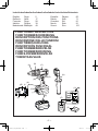 2
2
-
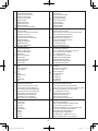 3
3
-
 4
4
-
 5
5
-
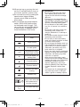 6
6
-
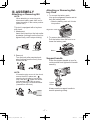 7
7
-
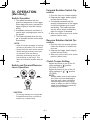 8
8
-
 9
9
-
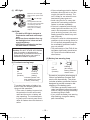 10
10
-
 11
11
-
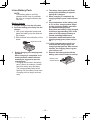 12
12
-
 13
13
-
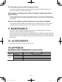 14
14
-
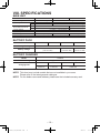 15
15
-
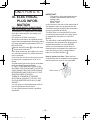 16
16
-
 17
17
-
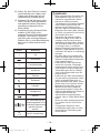 18
18
-
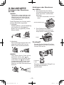 19
19
-
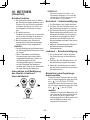 20
20
-
 21
21
-
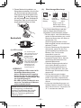 22
22
-
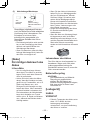 23
23
-
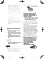 24
24
-
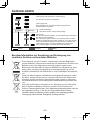 25
25
-
 26
26
-
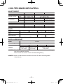 27
27
-
 28
28
-
 29
29
-
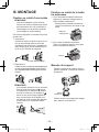 30
30
-
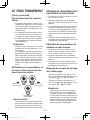 31
31
-
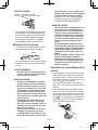 32
32
-
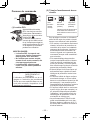 33
33
-
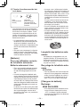 34
34
-
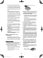 35
35
-
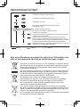 36
36
-
 37
37
-
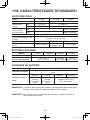 38
38
-
 39
39
-
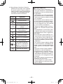 40
40
-
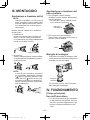 41
41
-
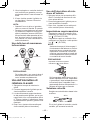 42
42
-
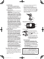 43
43
-
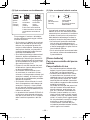 44
44
-
 45
45
-
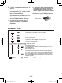 46
46
-
 47
47
-
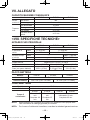 48
48
-
 49
49
-
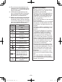 50
50
-
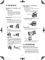 51
51
-
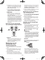 52
52
-
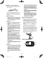 53
53
-
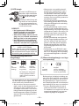 54
54
-
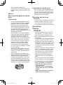 55
55
-
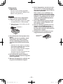 56
56
-
 57
57
-
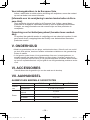 58
58
-
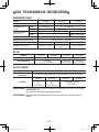 59
59
-
 60
60
-
 61
61
-
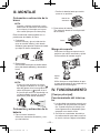 62
62
-
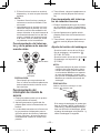 63
63
-
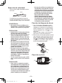 64
64
-
 65
65
-
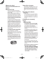 66
66
-
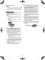 67
67
-
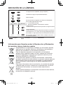 68
68
-
 69
69
-
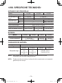 70
70
-
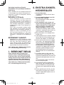 71
71
-
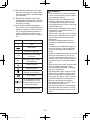 72
72
-
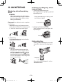 73
73
-
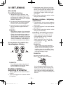 74
74
-
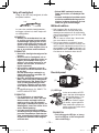 75
75
-
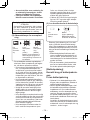 76
76
-
 77
77
-
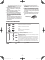 78
78
-
 79
79
-
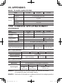 80
80
-
 81
81
-
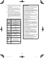 82
82
-
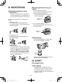 83
83
-
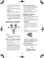 84
84
-
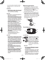 85
85
-
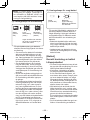 86
86
-
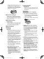 87
87
-
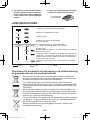 88
88
-
 89
89
-
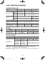 90
90
-
 91
91
-
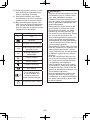 92
92
-
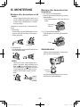 93
93
-
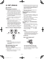 94
94
-
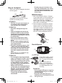 95
95
-
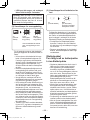 96
96
-
 97
97
-
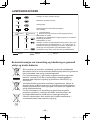 98
98
-
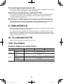 99
99
-
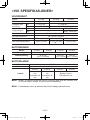 100
100
-
 101
101
-
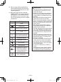 102
102
-
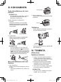 103
103
-
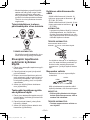 104
104
-
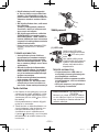 105
105
-
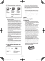 106
106
-
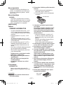 107
107
-
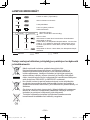 108
108
-
 109
109
-
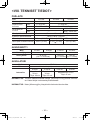 110
110
-
 111
111
-
 112
112


Panasonic ey 7450 ln2s Le manuel du propriétaire
- Catégorie
- Perceuses mixtes sans fil
- Taper
- Le manuel du propriétaire
dans d''autres langues
- italiano: Panasonic ey 7450 ln2s Manuale del proprietario
- español: Panasonic ey 7450 ln2s El manual del propietario
- Deutsch: Panasonic ey 7450 ln2s Bedienungsanleitung
- Nederlands: Panasonic ey 7450 ln2s de handleiding
- dansk: Panasonic ey 7450 ln2s Brugervejledning
- svenska: Panasonic ey 7450 ln2s Bruksanvisning
Documents connexes
-
Panasonic EY7549X Le manuel du propriétaire
-
Panasonic EY7840 Le manuel du propriétaire
-
Panasonic EY7880 Manuel utilisateur
-
-
Panasonic EY75A1 Le manuel du propriétaire
-
-
-
-
Panasonic EY7960 Manuel utilisateur
-