
Installation Instructions
M5 HEAD Part Number:
30892
©2019 Horizon Global Sheet 1 of 7 30892N 05/29/19 Rev. A
WARNING:Under no circumstances do we recommend exceeding the towing vehicle manufacturers recommended vehicle towing capacity.
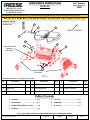
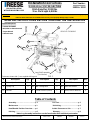
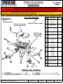
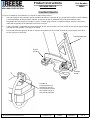
#Description Qty. #Description Qty. #Description Qty.
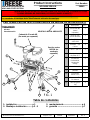
1Assembly –Head Unit 1 2 Handle 1 3 ½” Pull Pin 2
4Spring Clip 25a M8 Carriage Bolt 25b M8 Lock Washer 2
5c M8 Nut 26* Bolts & Washers 4
READ ALL INSTRUCTIONS BEFORE STARTING THE INSTALLATION
1. Assembly………..………………............p 2
2. Maintenance………………….………...p 3
3. Head/Handle Position Overview………p 4
4. Hitching…………….……...……………p 5
5. Pull Test………………..……..............p 5
6. Unhitching………..………………......p 6
7. Warranty………..….……..………….p 7
Table of Contents
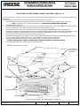
*Note: Leg Assembly instructions can be found under their individual part number
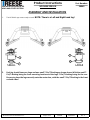
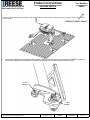
VEHICLE FORWARD
1
Legs Sold Separately
(GM shown)
2
3
4
5
5
4
3
Equipment Required:
Wrenches: M13
6*
FIG. 1
Fasteners shown with (*) are supplied with leg unit.
FOR INSTALLATION
WITH M5 MOUNTING LEGS
& CENTER SECTION
Center Section Sold
Separately
(20K shown)

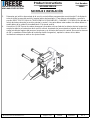
Assembly
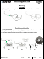
x 2
x 2
FIG. 2 FIG. 3
FIG. 6
FIG. 5
FIG. 4
Installation Instructions
HEAD Part Number:
30892
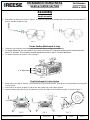
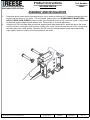
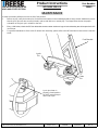
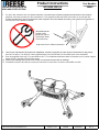
Handle Assembly
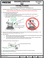
1. Slide tube over the bar as shown in figure 2, and securely tighten with carriage bolts, lock washers and nuts with M13 wrench.
Handle should be snug.
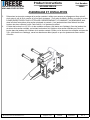
Head Attachment to Center Section
1. Apply grease per page 3, figures 7 & 8. Place head unit on top of center section as shown in figure 4, making sure to avoid putting
any body parts in pinch points
2. Insert pull pin as shown in figure 5, and secure with spring clips. Both sides required.
3. Inspect through sight holes on top of head pan to make sure clips are assembled correctly, as shown in figure 6
©2019 Horizon Global Sheet 2 of 7 30892N 05/29/19 Rev. A

Printed in Mexico
Typical Grease needle generally
available at auto parts stores
Installation Instructions
HEAD Part Number:
30892
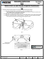
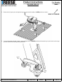
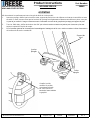
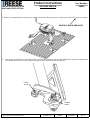
Grease location
Prior to installing head
Head
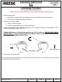
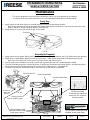
1. Preventative lubrication should be applied to the following to keep the head functioning properly;
A. Apply grease to skid plate surface to provide lubricated surface for attachment to trailer.
Note: Plastic lube plates can be used to avoid messy grease. Plate must not exceed 3/16” in thickness to ensure hitch works
properly. REESE 5th Wheel Lube Plate #83001 is recommended.
B. Apply grease to 5th wheel jaw and/or kingpin on the trailer.
C. Apply grease via the grease fitting on the top of the unit. (Grease needle required, see fig. 8) Head comes pre-greased
D. Apply spray on white lithium grease to internal mechanisms -rotate handle a few times to distribute the lubricant.
Note: May need to wipe down unit to remove large debris before application of grease.
Before First Use and Periodic Required Maintenance
C
B
D
A
FIG. 7
FIG. 8
©2019 Horizon Global Sheet 3 of 7 30892N 05/29/19 Rev. A

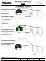
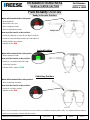
Ready-to-Receive Position:
When will the head will be in this position?
-When delivered
-When hitch not in use
-When coupling to trailer
-After uncoupling from trailer
How to tell the head is in this position:
-Handle is pulled out fully until audible “CLICK” is heard and holes
DO NOT align for bail pin
-Handle is easily movable towards cab, and returns to
default position upon release
-Indicator shows RED
Locked Position:
When will the head will be in this position?
-When coupled to trailer
How to tell the head is in this position:
-Handle is in a position that holes align
for bail pin insertion.
-Indicator ONLY shows GREEN
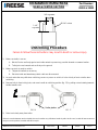
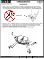
Unhitching Position:
When will the head will be in this position?
-When unhitching the trailer
How to tell the head is in this position:
-Handle is in position shown*
-Indicator shows RED
*If there is tension between truck and trailer, the truck or trailer may shift when handle is pulled. In this case, handle will start to return to
ready-to-receive position, but trailer will still uncouple.
Functionality Overview
FIG. 9
FIG. 10
FIG. 11
Installation Instructions
HEAD Part Number:
30892
RED
RED
GREEN
©2019 Horizon Global Sheet 4 of 7 30892N 05/29/19 Rev. A
Bail pin holes
DO NOT Align
Bail pin holes
Do Align

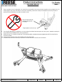
Hitching Procedure
Before hitching to a trailer, make sure your 5th wheel height is correct.
Information on how to properly set the height of your 5th wheel hitch can be found in the Leg Installation Instructions.
Failure to follow these instructions may result in death or serious injury
1) Make sure truck and trailer is in position to couple
A. Truck tailgate is lowered if necessary
B. Blocks/Chocks are firmly against each trailer wheel to prevent any possible forward or rearward motion.
C. Pin box is at correct height for hitching (fig. 12 & 13).
D. Make sure head is in Ready-to-Receive position (pg. 4, fig. 9) by pulling the handle out fully
until an audible “CLICK” is heard
2) Back truck slowly into trailer so the trailer king pin and 5th wheel funnel align. When the indicator turns completely green, the
trailer king pin is securely held by the 5th wheel jaw (pg. 4, fig. 10).*
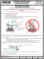
3) Perform Pull Test –
A. With trailer wheels still firmly blocked, trailer landing gears firmly on the ground supporting trailer weight, and trailer
brake on, make sure no one is between the truck and trailer.
B. Try to pull trailer slowly forward. If trailer is properly hitched, proceed to Step 4. If trailer is not properly hitched,
trailer will separate from hitch, and truck will move forward -repeat steps 1 thru 3.
4) Insert bail pin into lock hole, as shown in figure 14.
5) Connect electrical cable and breakaway switch cable between truck and trailer, raise tailgate if necessary.
6) Remove chocks/blocks and lift trailer jacks.
*Jaw may not close if under compression. If fully backed into trailer and not fully latched, pull truck slowly forward to remove load on jaw. Handle
will fully latch.
FIG. 12 FIG. 13
Bottom of Pin Box to be aligned
with top of Skid Plate ramp +/-1
inch
Bail pin shown inserted & locked
FIG. 14
CONTACT ZONE
+/-1in. from top of
skid plate ramp
Installation Instructions
HEAD Part Number:
30892
Indicator shows
Green
©2019 Horizon Global Sheet 5 of 7 30892N 05/29/19 Rev. A

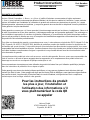
Unhitching Procedure
Failure to follow these instructions may result in death or serious injury
1) Make sure trailer is secure
A. Blocks/Chocks are firmly against each trailer wheel to prevent any possible forward or rearward motion.
B. Trailer jacks are lowered and are firmly on the ground
2) Make sure truck is ready to unhitch:
A. Tailgate is lowered if necessary
B. Electrical cable and breakaway switch cable are disconnected.
3) Remove bail pin and move handle to unhitching position (pg. 4, fig. 11) by pulling out fully (fig. 15) until an audible “CLICK” is
heard then rotating handle towards cab (fig. 16).*
4) Drive truck slowly away from trailer
*If there is tension between truck and trailer, the truck or trailer may shift when handle is pulled. In this case, handle will start to return to ready-to-
receive position, but trailer will still uncouple.
FIG. 15 FIG. 16
Installation Instructions
HEAD Part Number:
30892
©2019 Horizon Global Sheet 6 of 7 30892N 05/29/19 Rev. A
Trailer pin box VEHICLE FORWARD
If handle will not move to the unhitching position (pg. 4, fig. 11) with ease, STOP, DO NOT FORCE
THE HANDLE!!! The jaw may not open if under tension. Slowly reverse truck to remove load on
the jaw before attempting to unhitch trailer.

Installation Instructions
Head
NOTES:
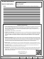
Horizon Global
47912 Halyard Drive Suite 100
Plymouth, MI 48170
LIMITED LIFETIME WARRANTY
1. Limited Lifetime Warranty (“Warranty”). Horizon Global (“We” or “Us”) warrants to the original consumer purchaser only
(“You”) that the product will be free from material defects in both material and workmanship for a period of lifetime of
ownership, ordinary wear and tear excepted; provided that installation and use of the product is in accordance with product
instructions. There are no other warranties, express or implied, including the warranty of merchantability or fitness for a
particular purpose. This warranty is not transferable.
2. Limitations on the Warranty. This Warranty does not cover: (a) normal wear and tear; (b) damage through abuse, neglect,
misuse, or as a result of any accident or in any other manner; (c) damage from misapplication, overloading, or improper
installation; (d) improper maintenance and repair; and (e) product alteration in any manner by anyone other than Us, with the
sole exception of alterations made pursuant to product instructions and in a workmanlike manner.
3. Obligations of Purchaser. To make a Warranty claim, contact Us at 47912 Halyard Drive Suite 100, Plymouth, MI, 48170,
1-800-632-3290, identify the product by model number, and follow the claim instructions that will be provided. Any returned
product that is replaced by Us becomes our property. You will be responsible for return shipping costs. Please retain your
purchase receipt to verify date of purchase and that You are the original consumer purchaser. The product and the purchase
receipt must be provided to Us in order to process Your warranty claim.
4. Remedy Limits. Product replacement is Your sole remedy under this Warranty. We shall not be liable for service or labor
charges incurred in removing or replacing a product or any incidental or consequential damages of any kind.
5. Assumption of Risk. You acknowledge and agree that any use of the product for any purpose other than the specified use(s)
stated in the product instructions is at Your own risk.
6. Governing Law. This Warranty gives You specific legal rights, and You also may have other rights which vary from state
to state. This Warranty is governed by the laws of the State of Michigan, without regard to rules pertaining to conflicts of
law. The state courts located in Oakland County, Michigan shall have exclusive jurisdiction for any disputes relating to this
Warranty.
Part Number Purchased:
Place of Purchase:
Date of Purchase:
Part Manufactured Date (located on driver-side sticker):
©2019 Horizon Global Sheet 7 of 7 30892N 05/29/19 Rev. A

fInstallation Instructions
M5 HEAD & CENTER SECTION
Hitch Rated for 32,000 lbs,
Max. Pin Weight 6,400 lbs
Part Number:
30892 & 30932
©2020 Horizon Global America Inc. Sheet 1 of 8 30932N 04/20/20 Rev. A
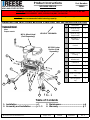
# Description Qty. # Description Qty. # Description Qty.
1 Assembly –Head Unit 1 2 Handle 1 3 ½” Pull Pin 2
4 Spring Clip 2 5a M8 Carriage Bolt 2 5b M8 Lock Washer 2
5c M8 Nut 2 6 Center Section (30932) 1 7* Bolts, Nuts & Washers 4
READ ALL INSTRUCTIONS BEFORE STARTING THE INSTALLATION
Assembly………..………………..........p 2
Maintenance………………….………..p 3
Head/Handle Position Overview……p 4
Hitching…………….……...……………p 5
Pull Test………………..……..............p 5
Unhitching………..………………......p 6
Added Clearance to Cab…....………p 7
Warranty………..….……..….……….p 8
Table of Contents
*Note: Leg Assembly instructions can be found under their individual part number
VEHICLE FORWARD
1
Legs Sold Separately
(Ford shown)
2
3
4
5
5
4
3
Equipment Required:
•Fastener kit 30892F
•M13, M24 socket and wrench
•Torque Wrench
•Lithium Grease
6
7*
FIG. 1
Fasteners shown with (*) are supplied with leg unit.
FOR INSTALLATION
WITH M5 MOUNTING LEGS
WARNING: Under no circumstances do we recommend exceeding the towing vehicle manufacturers recommended vehicle towing capacity.
Failure to follow instructions for installation and use may cause property damage, injury or death.
7*
7*

Handle Assembly
1. Slide tube over the bar as shown in figure 2, and securely tighten with carriage bolts, lock washers and nuts with M13
wrench. Handle should be snug.
Center Section Attachment to Legs
1. Fasteners and assembly instructions are included with the set of legs, sold separately.
2. For height adjustment, the unit should be set to have a minimum of 6” clearance between the truck bed rail and the
bottom of the trailer. This unit has 3 possible attachment locations, with 4” of overall adjustment.
3. For added clearance to the truck cab, see page 7.
Head Attachment to Center Section
1. Apply grease per page 3, figure 9. Place head unit on top of center section, making sure to avoid putting any body parts
in pinch points
2. Insert pull pin as shown in figure 6, and secure with spring clips. Both sides required.
3. Inspect through sight holes on top of head pan to make sure clips are assembled correctly, as shown in figure 7
Assembly
x 2
x 2
FIG. 2 FIG. 3
FIG. 7FIG. 6FIG. 5
Installation Instructions
HEAD & CENTER SECTION Part Number:
30892 & 30932
4” of Adjustment
FIG. 4
©2020 Horizon Global America Inc. Sheet 2 of 8 30932N 4/20/20 Rev. A
Pinch areas
Sight Holes

Printed in Mexico
Typical Grease needle generally
available at auto parts stores
Installation Instructions
HEAD & CENTER SECTION Part Number:
30892 & 30932
Grease location
Prior to installing head
Hole provided for 5/16”
eye bolt to attach trailer
break-away cable to.
Pivot Grease fitting.
Accessible thru logo/load
rating slot. Use of grease
needle required.
Maintenance
FIG. 9A
©2020 Horizon Global America Inc. Sheet 3 of 8 30932N 4/20/20 Rev. A
FIG. 9B
Pivot bolt and nut
Access for
open end
wrench
This unit is designed to need very little maintenance and be one of the quietest on the market.
In order to ensure long term performance, it is recommended to lubricate as indicated below;
Every Use
1. Apply grease to skid plate surface, to provide lubricated surface for attachment to trailer.
Note: Plastic lube plates can be used to avoid messy grease. Plate must not exceed 3/16” in thickness to ensure hitch works
properly. REESE 5th Wheel Lube Plate #83001 is recommended.
2. Apply grease to 5th wheel jaw and/or kingpin on the trailer.
Jaw
Skid Plate
FIG. 8
Annually/As Required
1. Apply grease via the grease fitting on the top of the unit. (Grease needle required, see fig. 9) Head comes pre-greased
2. Apply spray on white lithium grease to internal mechanisms - rotate handle a few times to distribute the lubricant.
Note: May need to wipe down unit to remove large debris before application of grease.
3. Greasing the pivot assemblies can easily be done with a grease gun that has a needle adapter installed.
4. The pivot assembly resistance is preset at factory. If head pivots and makes noise when trailer is not attached, adjust
the resistance more by tighten pivot bolt 1/2 turn at a time (2 full turns max.). See figure 9B.
5. The pivot assembly can be rebuilt if require. Instructions to do this will be in rebuild kit.
Head Grease fitting
Internal Mechanisms

Ready-to-Receive Position:
When will the head will be in this position?
- When delivered
- When hitch not in use
- When coupling to trailer
- After uncoupling from trailer
How to tell the head is in this position:
- Handle is pulled out so holes do not align for bail pin
- Handle is easily movable towards cab, and returns to
default position upon release
- Indicator shows RED
Locked Position:
When will the head will be in this position?
- When coupled to trailer
How to tell the head is in this position:
- Handle is in a position that holes align
for bail pin insertion.
- Indicator ONLY shows GREEN
Unhitching Position:
When will the head will be in this position?
- When unhitching the trailer
How to tell the head is in this position:
- Handle is in position shown*
- Indicator shows RED
*If there is tension between truck and trailer, the truck or trailer may shift when handle is pulled. In this case, handle will start to return to
ready-to-receive position, but trailer will still uncouple.
Functionality Overview
FIG. 10
FIG. 11
FIG. 12
Installation Instructions
HEAD & CENTER SECTION Part Number:
30892 & 30932
RED
RED
GREEN
©2020 Horizon Global America Inc. Sheet 4 of 8 30932N 4/20/20 Rev. A
Bail pin hole

Hitching Procedure
Before hitching to a trailer, make sure your 5th wheel height is correct.
Information on how to properly set the height of your 5th wheel hitch can be found in the Leg Installation
Instructions.
Failure to follow these instructions may result in death or serious injury
1) Make sure truck and trailer is in position to couple
A. 5th wheel is correctly secured to truck
B. Truck tailgate is lowered if necessary
C. Blocks/Chocks are firmly against each trailer wheel to prevent any possible forward or rearward motion.
D. Pin box is at correct height for hitching (fig. 13 & 14).
E. Make sure head is in Ready-to-Receive position (pg. 4, fig.10)
2) Back truck slowly into trailer so the trailer king pin and 5th wheel funnel align. Hitch will latch automatically when truck is
backed completely into trailer king pin. When this occurs, the indicator will be 100% green (pg. 4, fig. 11).*
3) Perform Pull Test –
A. With trailer wheels still firmly blocked, trailer landing gears firmly on the ground supporting trailer weight, and
trailer brake on, make sure no one is between the truck and trailer.
B. Try to pull trailer slowly forward. If trailer is properly hitched, proceed to Step 4. If trailer is not properly
hitched, trailer will separate from hitch, and truck will move forward - repeat steps 1 thru 3.
4) Insert bail pin into lock hole, as shown in figure 15, or lock for added security. Possible lock dimensions shown on
page 6.
5) Connect electrical cable and breakaway switch cable between truck and trailer, raise tailgate if necessary.
6) Remove chocks/blocks and lift trailer jacks.
*Jaw may not close if under compression. If fully backed into trailer and not fully latched, pull truck slowly forward to remove load on jaw.
Handle will fully latch.
FIG. 13 FIG. 14
Bottom of Pin Box to be aligned
with top of Skid Plate ramp +/-
1 inch
Bail pin shown inserted & locked
FIG. 15
CONTACT ZONE
+/- 1in. from top of
skid plate ramp
Installation Instructions
HEAD & CENTER SECTION Part Number:
30892 & 30932
Indicator shows
Green
©2020 Horizon Global America Inc. Sheet 5 of 8 30932N 4/20/20 Rev. A

Unhitching Procedure
Failure to follow these instructions may result in death or serious injury
1) Make sure trailer is secure
A. Blocks/Chocks are firmly against each trailer wheel to prevent any possible forward or rearward motion.
B. Trailer jacks are lowered and are firmly on the ground
2) Make sure truck is ready to unhitch:
A. Tailgate is lowered as necessary
B. Electrical cable and breakaway switch cable are disconnected.
3) As truck and trailer may shift when unhitching, ensure no person or vehicle is in the vicinity of truck or trailer when
unhitching
4) Remove bail pin from locking hole, and move handle to unhitching position (fig. 17) by pulling out and rotating towards
handle towards cab.*
5) Drive truck slowly away from trailer
*If there is tension between truck and trailer, the truck or trailer may shift when handle is pulled. In this case, handle will start to return to
ready-to-receive position, but trailer will still uncouple.
FIG. 16 FIG. 17
Installation Instructions
HEAD & CENTER SECTION Part Number:
30892 & 30932
©2020 Horizon Global America Inc. Sheet 6 of 8 30932N 4/20/20 Rev. A
Trailer pin box
1-1/2”
or greater
3/4” or greater
Ø 5/16” or less

Printed in Mexico
TO INCREASE THE GAP BETWEEN TRAILER AND TRUCK CAB by 1-1/2”.
Logo/Rating cover
Plastic retainers
Grease points
Grease points
Head springs
View holes to
help spring clip
installation
Installation Instructions
HEAD & CENTER SECTION Part Number:
30892 & 30932
FIG. 18
©2020 Horizon Global America Inc. Sheet 7 of 8 30932N 4/20/20 Rev. A
Head spring
assembly
Pinch
points
Pinch
points
Shown in factory location with offset towards cab of truck
The center section has an option to increase the gap between the trailer front and the truck cab by 1-1/2” by rotating the center section
180 degrees.
Location of king pin should be ahead of truck rear axle and have proper truck cab clearance
1. Remove the head by pulling the spring clips off the head retainer pins. Then pull the head retainer pin out of the head.
Hint; A slight push down on the head will help this. Caution, avoid getting fingers pinched.
2. Lift the head off and set aside.
3. Remove the bolts holding the legs on the center section and rotate the center section (all vehicles), OR disconnect the feet from
the bed and rotate the center section and leg assembly (not possible with RAM vehicles).
4. Re connect the center section or the center section and leg assembly per the installation instructions of that portion.
5. Remove the logo/rating cover by gently prying the two lower plastic retainers with the cover away from the center section. Avoid
scratching the paint by using plastic auto trim tools. The top will pivot and pull away once the cover rotates up enough.
6. Re-install on the other side (truck rear) by reversing the above process.
7. Remove the head springs by removing the 1/4” bolt (7/16” socket) and flip them from right to left. When installed properly, the
springs should be pointing up towards the truck cab and tighten to 7-8 ft-lbs. Springs will flex freely.
8. Re apply grease to the head and center section interface and re-install the head per instructions.
Caution; place hands or fingers on either side of the pivot interface to prevent pinching.
9. Re-install head retainer pins and clips per head instructions.
*30894 27k Center section shown

Product Instructions:
Head & Center Section
NOTES:
Horizon Global America, Inc
47912 Halyard Drive Suite 100
Plymouth, MI 48170
LIMITED LIFETIME WARRANTY
1. Limited Lifetime Warranty (“Warranty”). Horizon Global (“We” or “Us”) warrants to the original consumer purchaser
only (“You”) that the product will be free from material defects in both material and workmanship for a period of
lifetime of ownership, ordinary wear and tear excepted; provided that installation and use of the product is in
accordance with product instructions. There are no other warranties, express or implied, including the warranty of
merchantability or fitness for a
particular purpose. This warranty is not transferable.
2. Limitations on the Warranty. This Warranty does not cover: (a) normal wear and tear; (b) damage through abuse,
neglect, misuse, or as a result of any accident or in any other manner; (c) damage from misapplication, overloading,
or improper installation; (d) improper maintenance and repair; and (e) product alteration in any manner by anyone
other than Us, with the sole exception of alterations made pursuant to product instructions and in a workmanlike
manner.
3. Obligations of Purchaser. To make a Warranty claim, contact Us at 47912 Halyard Drive Suite 100, Plymouth, MI,
48170, 1-800-632-3290, identify the product by model number, and follow the claim instructions that will be provided.
Any returned product that is replaced by Us becomes our property. You will be responsible for return shipping costs.
Please retain your purchase receipt to verify date of purchase and that You are the original consumer purchaser.
The product and the purchase receipt must be provided to Us in order to process Your warranty claim.
4. Remedy Limits. Product replacement is Your sole remedy under this Warranty. We shall not be liable for service
or labor charges incurred in removing or replacing a product or any incidental or consequential damages of any kind.
5. Assumption of Risk. You acknowledge and agree that any use of the product for any purpose other than the
specified use(s) stated in the product instructions is at Your own risk.
6. Governing Law. This Warranty gives You specific legal rights, and You also may have other rights which vary from
state to state. This Warranty is governed by the laws of the State of Michigan, without regard to rules pertaining to
conflicts of law. The state courts located in Oakland County, Michigan shall have exclusive jurisdiction for any
disputes relating to this Warranty.
Part Number Purchased:
Place of Purchase:
Date of Purchase:
Part Manufactured Date (located on driver-side sticker):
©2020 Horizon Global America Inc. Page 8 of 8 30932N 04/20/20 Rev. A

Product Instructions
M5 RAM 32K LEG
Part Number:
30949
FOR INSTALLATION WITH M5
HEAD AND CENTER SECTION
© 2021 Horizon Global America Inc. 30949N 04/20/2021 Rev. A
Page 1 of 21
10
1. Installation ---------------------------- p 1
2. Assembly and Installation ------- p 2 - 5 3. Maintenance ------------------------------- p 6
4. Warranty ------------------------------------ p 7
CAUTION: Under no circumstances do we recommend exceeding the towing vehicle
manufacturers recommended vehicle towing capacity.
READ ALL INSTRUCTIONS BEFORE STARTING THE INSTALLATION OR USE
Table of Contents
VEHICLE FORWARD
5
1
M5 5th Wheel Head
(Sold Separately)
FIG. 1
4
M5 32K Center
Section (Sold
Separately)
6
2
8
7
9
WARNING: FAILURE TO FOLLOW INSTALLATION AND HITCH-UP INSTRUCTIONS MAY
CAUSE PROPERTY LOSS, SERIOUS INJURY, OR DEATH!
Equipment Required:
Wrenches: 15/16”
Pliers
Torque wrench
# Description QTY.
1 M5 Ram Leg
(Left Hand) 1
2 M5 Ram Leg
(Right Hand) 1
3 Bolt-5/8-11 x
4.25” GR8 4
4 Washer – 5/8”
Conical 4
5 Nut – 5/8”-11 4
6 Handle, T-Pin
Locking 4
7 Lynch Pin,
Handle Lock 4
8 Castle Nut 4
9 Cotter Pin 8
10 Front T-
Pin Ram
Leg 2
11 Rear T-Pin Ram
Leg 2
12 T-Bushing Ram
Leg 4
3
11
12
11

Product Instructions
M5 RAM 32K LEG
Part Number:
30949
FOR INSTALLATION WITH M5
HEAD AND CENTER SECTION
© 2021 Horizon Global America Inc. 30949N 04/20/2021 Rev. A
Page 2 of 21
1. The M5 RAM Legs comes ready to install. NOTE: There is a Left and Right hand leg!
2. Each leg should have one large and one small T-Pin/T-Bushing as shown above. With the small T-
Pin/T-Bushing being the front mounting location and the large T-Pin/T-Bushing being for the rear.
Be sure to place the legs correctly onto the center box, with the small T-Pin/T-Bushing in the front
on both sides!
11
11
10
ASSEMBLY AND INSTALLATION
SMALL LARGE
9

Product Instructions
M5 RAM 32K LEG
Part Number:
30949
FOR INSTALLATION WITH M5
HEAD AND CENTER SECTION
© 2021 Horizon Global America Inc. 30949N 04/20/2021 Rev. A
Page 3 of 21
3. Determine which center section mounting holes to use to ensure a minimum of 6” clearance between the truck
bed rail and the bottom of the trailer. ( For more detail, please refer to the GUIDELINES FOR MATCHING
HITCH, TRUCK, AND TRAILER section located in the head and center section instruction sheet.) Legs should
be attached at same height on both sides of unit. This unit has 4” of vertical adjustment.
4. Using the (4) 5/8” Hex Head Bolts and conical washers (teeth side toward hitch), attach the legs to the center
section structure, inserting the bolts from the outside of the center section through the bolt hole in the legs and
into the inside of the center section. Thread on the 5/8” nuts and conical washers (teeth side toward hitch),
finger tighten fasteners initially until final adjustments are made.
ASSEMBLY AND INSTALLATION

Product Instructions
M5 RAM 32K LEG
Part Number:
30949
FOR INSTALLATION WITH M5
HEAD AND CENTER SECTION
© 2021 Horizon Global America Inc. 30949N 04/20/2021 Rev. A
Page 4 of 21
5. Remove the (4) lynch pins and position legs over pucks with handles in OPEN position as shown.
6. Once unit has been placed in pucks, rotate handles back to CLOSED position and insert the lynch pins back into the leg to
prevent handles from opening during operation.
VEHICLE FORWARD
Lynch
Pin
Cotter
Pin

Product Instructions
M5 RAM 32K LEG
Part Number:
30949
FOR INSTALLATION WITH M5
HEAD AND CENTER SECTION
© 2021 Horizon Global America Inc. 30949N 04/20/2021 Rev. A
Page 5 of 21
7. Due to variations in truck underbeds, it is normal for some handles to be loose and other handles to be too tight to lock. If a
handle appears too loose and rattles or cannot be closed fully, remove the cotter pin and adjust castle nut by hand to a
position where handle does not rattle or is able to close.
8. Once handle adjustment is satisfactory, re-insert cotter pin and bend end with pliers to hold in place. Additional cotter pins
are provided in the hardware kit for your convenience.
9. With Ram Leg T-Pin handles locked and T-Pins securely held in underbed structure, tighten each 5/8” hex-head bolt to
210 ft-lb of torque.
10. Verify that hitch is tight to truck bed by lifting each side of the hitch.
11. Assemble head to center section per instructions included with M5 Center Section and Head.
Finger tighten castle nut only!
(Do not install cotter pin
until final adjustments
are made)
La page est en cours de chargement...
La page est en cours de chargement...
La page est en cours de chargement...
La page est en cours de chargement...
La page est en cours de chargement...
La page est en cours de chargement...
La page est en cours de chargement...
La page est en cours de chargement...
La page est en cours de chargement...
La page est en cours de chargement...
La page est en cours de chargement...
La page est en cours de chargement...
La page est en cours de chargement...
La page est en cours de chargement...
La page est en cours de chargement...
La page est en cours de chargement...
-
 1
1
-
 2
2
-
 3
3
-
 4
4
-
 5
5
-
 6
6
-
 7
7
-
 8
8
-
 9
9
-
 10
10
-
 11
11
-
 12
12
-
 13
13
-
 14
14
-
 15
15
-
 16
16
-
 17
17
-
 18
18
-
 19
19
-
 20
20
-
 21
21
-
 22
22
-
 23
23
-
 24
24
-
 25
25
-
 26
26
-
 27
27
-
 28
28
-
 29
29
-
 30
30
-
 31
31
-
 32
32
-
 33
33
-
 34
34
-
 35
35
-
 36
36


dans d''autres langues
- English: Reese 30950 Installation guide
- español: Reese 30950 Guía de instalación