
N96_AC
TRANSLATION OF ORIGINAL OPERATING AND
INSTALLATION INSTRUCTION
ENGLISH
KNF 329772-329775 09/23 EN-US
OEM
Notice!
Before operating the pump and accessories, read and observe the operating and installation instructions as
well as the safety information!
DIAPHRAGM PUMP

Index
1 About this document .........................................................3
1.1 Using the operating and installation instructions.......3
1.2 Exclusion of liability...................................................3
1.3 Symbols and markings..............................................3
1.4 List of abbreviations ..................................................5
2 Safety ................................................................................6
2.1 Personnel and target group ......................................6
2.2 Responsibility of the operator ...................................6
2.3 Working in a safety conscious manner .....................7
2.4 Operating conditions .................................................7
2.5 Media ........................................................................7
2.6 Use............................................................................8
2.7 Directives and standards ..........................................9
2.8 Customer service and repair.....................................9
2.9 Disposal ....................................................................9
3 Technical data.................................................................10
Technical data.........................................................10
4 Product description .........................................................13
5 Transport.........................................................................15
General ...................................................................15
6 Installation and connection..............................................16
6.1 Installing the pump..................................................16
6.2 Electrical connection ...............................................18
6.3 Pneumatic connection.............................................19
7 Operation ........................................................................20
7.1 General ...................................................................20
7.2 Information on switching the pump on and off ........22
8 Servicing .........................................................................23
8.1 Servicing schedule..................................................23
8.2 Cleaning..................................................................23
8.3 Replacing diaphragm and valve plates ...................24
9 Spare parts and accessories...........................................28
9.1 Spare parts .............................................................28
9.2 Accessories.............................................................28
10 Troubleshooting ..............................................................29
11 Returns............................................................................31
KNF Neuberger GmbH
Alter Weg 3
79112 Freiburg
Germany
Tel. +49 (0)7664/5909-0
Fax. +49 (0)7664/5909-99
www.knf.com

Diaphragm pump N96_AC About this document
Translation of Original Operating and Installation Instruction, english, KNF 329772-329775 09/23 3
1 About this document
1.1 Using the operating and installation instructions
The operating and installation instructions are part of the pump.
àIn the event of uncertainties with regard to the content of the operating
and installation instructions, please contact the manufacturer (contact
data: see www.knf.com). Please have the type and serial number of
the pump ready.
àRead the operating and installation instructions before you commission
the pump.
àGive the operating and installation instructions only completely and un-
changed to the next owner.
àKeep the operating and installation instructions within reach at all
times.
Project pumps For customer-specific project pumps (pump models that begin with "PJ" or
"PM"), there may be deviations from these operating and installation in-
structions.
àFor project pumps, also observe the agreed specifications.
Optional contents Project-specific options may be included in the operating and assembly in-
structions. These are marked with "Optional". It is also possible that
project-specific deviations are not included in the operating and assembly
instructions.
1.2 Exclusion of liability
The manufacturer assumes no liability for damages and malfunctions re-
sulting from failure to observe the operating and installation instructions.
The manufacturer assumes no liability for damages and malfunctions re-
sulting from changes or modifications to the device and improper handling.
The manufacturer assumes no liability for damages and malfunctions re-
sulting from impermissible spare parts and accessories.
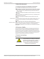
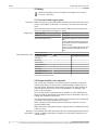
1.3 Symbols and markings
Warning notice
WARNING
A notice that warns you of danger is located here.
Possible consequences of a failure to observe the
warning notice are specified here. The signal
word, e.g., Warning, indicates the danger level.
àMeasures for avoiding the danger and its
consequences are specified here.

About this document Diaphragm pump N96_AC
4 Translation of Original Operating and Installation Instruction, english, KNF 329772-329775 09/23
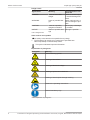
Danger levels
Signal word Meaning Consequences if not
observed
DANGER warns of immediate
danger
Death or serious injury
or serious damage will
result.
WARNING warns of possible dan-
ger
Death, serious injury or
serious damage is pos-
sible.
CAUTION warns of a possibly
dangerous situation
Minor injury or damage
is possible.
NOTICE Warns of possible dam-
age
Damage is possible.
Tab.1 Danger levels
Other notices and symbols
àAn activity to be carried out is specified here (a step).
1. The first step of an activity to be carried out is specified here.
Other sequentially numbered steps follow.
This symbol indicates important information.
Explanation of pictograms
Pictogram Meaning
General warning symbol
Warning of hot surface
Warning of electrical voltage
Warning of poisonous substances
Warning of hand injuries through crushing
Observe the operating instructions
General mandatory sign
Tab.2 Explanation of pictograms

Diaphragm pump N96_AC About this document
Translation of Original Operating and Installation Instruction, english, KNF 329772-329775 09/23 5
1.4 List of abbreviations
Abbreviation Term
PTFE Polytetrafluoroethylene
FFKM Perfluoro rubber
PVDF Polyvinylidene fluoride
PP Polypropylene
FKM Fluororubber
FEP Fluoroethylene propylene
ETFE Ethylene tetrafluoroethylene copolymer
TFM Modified PTFE
Tab. Table
Fig. Figure
a/o And/or
e.g. For example
Perm. Permissible
et al. And the like
opt. If necessary
Max. Maximum
Min. Minimum
PWM Pulse Width Modulation
CW Clockwise
CCW Counter-Clockwise
TTL Transistor-Transistor Logic
DC Direct Current
GND Ground
KF Small flange

Safety Diaphragm pump N96_AC
6 Translation of Original Operating and Installation Instruction, english, KNF 329772-329775 09/23
2 Safety
Observe the safety notices in Chapters 6 Installation and connec-
tion and 7 Operation.
2.1 Personnel and target group
Personnel Make sure that only specially trained and instructed personnel work on the
pumps. This applies, in particular, to mounting, connection and servicing
work.
Make sure that the personnel have read and understood the operating in-
structions, particularly the chapter on safety.
Target group Target group Definition
User Employee
Specialized personnel Specialized personnel are personnel
who
- have relevant professional training
in the field covered in the particular
section of text;
- have current knowledge of the field
covered in the particular section of
text.
Tab.3 Target group
Who-does-what matrix Lifecycle phase User Specialized personnel
Transport X
Mounting X
Connection X
Commissioning X X
Operation X X
Servicing X
Troubleshooting X
Disposal X
Tab.4 Who-does-what matrix
2.2 Responsibility of the operator
The pumps are produced in accordance with the generally recognized
rules of engineering, as well as the occupational health, safety and acci-
dent prevention regulations. Nevertheless, dangers can arise during their
use that lead to injuries to the user or third parties or to damage to the
pump or other property.
Only use the pumps in perfect technical condition, for their intended use,
safely and with an awareness of the dangers and in observation of the op-
erating and installation instructions.
The components that are to be connected to the pumps must be designed
according to the pneumatic data of the pumps.
When connecting the pumps to the electrical power, observe the corre-
sponding safety rules.
Make sure that no hazardous situation, physical harm or impairment of the
pump can occur.
Operating
parameters
Only operate and install the pump under the operating parameters and op-
erating conditions described in Chapters 2.4 Operating conditions and 3
Technical data.

Diaphragm pump N96_AC Safety
Translation of Original Operating and Installation Instruction, english, KNF 329772-329775 09/23 7
2.3 Working in a safety conscious manner
Observe the regulations on accident prevention and safety during all work
on the pumps and during operation.
Avoid contact with the pump heads and housing parts because the pump
heats up during operation.
When working on the pump, make sure that the pump is disconnected
from mains and without power.
When connecting the pump to the electrical mains, observe the corre-
sponding safety rules.
Ensure that no hazards arise from gas flowing when gas connections are
open, from the effects of noise or from hot, corrosive, dangerous and envi-
ronmentally hazardous gases.
Make sure that an EMC-compliant installation of the pump is ensured at all
times to prevent the occurrence of dangerous situations.
2.4 Operating conditions
Only use the pump in perfect technical condition, for its intended purpose,
safely and with an awareness of the dangers and in observation of the op-
erating instructions.
Only install and operate the pumps in accordance with the operating pa-
rameters and conditions described in Chapter 3 Technical data.
Only pumps that are fully assembled and in the condition as delivered may
be operated.
Make sure that the installation location is dry and that the pump is pro-
tected from rain, splash water, gushing water, dripping water and other
contamination.
Check the tightness of the connections between the pipes of the applica-
tion and the pump (or the connection of the pump) at regular intervals.
Leaky connections carry the risk of releasing dangerous gases and vapors
from the pump system.
2.5 Media
Requirements of pumped media Before transferring a medium, check whether the medium can be trans-
ferred without risk in the specific application.
Take note of any change in the state of matter (condensation, crystalliza-
tion).
Before using a medium, check the compatibility of the media-contacting
components (see 3 Technical data) with the medium.
Risk of dangerous gas mixtures during pump operation if diaphragm
breaks: Depending on the medium being transferred, breakage of the di-
aphragm can result in a dangerous mixture if the medium mixes with the
air in the compressor housing or the surroundings.
Only transfer gases that remain stable under the pressures and tempera-
tures that arise in the pump.
Handling of
hazardous
media
Upon breakage of the diaphragm and/or leaks, the transferred medium
mixes with the air in the surroundings and/or in the pump housing.
Make sure that a dangerous situation cannot arise as a result.
When pumping hazardous media, observe the safety regulations for the
handling of said media.
Handling of combustible media Note that the pump is not designed to be explosion-proof.
Make certain that the temperature of the medium is always sufficiently be-
low the ignition temperature of the medium so as to prevent ignition or ex-
plosion. This also applies for abnormal operating situations.

Safety Diaphragm pump N96_AC
8 Translation of Original Operating and Installation Instruction, english, KNF 329772-329775 09/23
Note that the temperature of the medium increases when the pump com-
presses the medium.
Therefore, make certain that the temperature of the medium also remains
sufficiently below the ignition temperature of the medium even when it is
compressed to the maximum permissible operating pressure of the pump.
The maximum permissible operating pressure of the pump is stated in
Chapter 3 Technical data.
Make certain that the permissible ambient temperature (see 3 Technical
data) is not exceeded.
Where applicable, also take into account external energy sources (such as
radiated heat sources) that could additionally heat the medium.
In case of doubt, contact KNF Customer Service.
2.6 Use
2.6.1 Proper use
The pumps are intended exclusively for transferring gases and vapors.
The pumps are intended exclusively for operation in indoor areas and in
non-explosive atmospheres.
2.6.2 Foreseeable misuse
The pumps must not be operated in explosive atmospheres.
The pumps are not suitable for transferring the following:
§Dusts
§Liquids
§Aerosols
§Biological and microbiological substances
§Fuels
§Explosives and flammable materials
§Fibers
§Oxidizing agents
§Foodstuffs.
As standard, the pumps must not be used for simultaneous generation of a
vacuum and positive pressure.
This function can be made possible on a project basis following consulta-
tion with KNF Customer Service.
Do not apply positive pressure to the inlet of the pump.
This function can be made possible on a project basis following consulta-
tion with KNF Customer Service.

Diaphragm pump N96_AC Safety
Translation of Original Operating and Installation Instruction, english, KNF 329772-329775 09/23 9
2.7 Directives and standards
EU/EC
Directives
Declaration of incorporation – for partly completed machinery
With respect to the Machinery Directive 2006/42/EC, the pumps are partly
completed machinery and are, therefore, to be regarded as not ready for
use. Partly completed machinery may not be commissioned until it has
been determined that the machine into which the partly completed machin-
ery is to be installed complies with the provisions of the Machinery Direc-
tive 2006/42/EC. The following fundamental requirements of Annex I of Di-
rective 2006/42/EC (general principles) are applied and observed:
§General principles no. 1
§No. 1.1.2. / 1.1.3. / 1.3.1. / 1.3.3. / 1.3.4. / 1.4.1. / 1.5.1. / 1.5.2. /
1.5.8. / 1.5.9. / 1.7.4. / 1.7.4.1. / 1.7.4.3.
Standards The following standards apply:
§EN IEC 61000-6-2
§EN IEC 61000-6-3
§EN IEC 63000
The protective goals of the following directive(s) are achieved:
§Directive 2011/65/EU on the restriction of the use of certain hazardous
substances in electrical and electronic equipment (Annex II changed
by delegated Directive (EU) 2015/863 of the Commission)
2.8 Customer service and repair
Customer service and repairs The pump is maintenance-free. However, KNF recommends periodic in-
spection of the pump for obvious changes in noise or vibration.
Only have repairs to the pumps performed by qualified KNF personnel.
Housings with electrically live components may only be opened by special-
ist personnel.
Use only genuine spare parts from KNF when performing servicing work.
2.9 Disposal
Environmental protection Store the pump and all accessories in accordance with the environmental
provisions. Observe national and international regulations. This applies in
particular to parts that are contaminated with toxic substances.
If you no longer need your packaging materials (e.g. for return shipment or
other transport of the device), dispose of them in an environmentally
friendly manner.
Old devices must not be disposed of with household waste. Proper dis-
posal and recycling helps to protect natural resources and the environ-
ment. The end user is responsible for disposing of old devices according to
national and international regulations. Alternatively, KNF products (old de-
vices) may also be returned to KNF for a fee (see chapter 11 Returns).

Technical data Diaphragm pump N96_AC
10 Translation of Original Operating and Installation Instruction, english, KNF 329772-329775 09/23
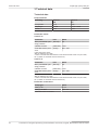
3 Technical data
Technical data
Pump materials
Assembly Material
KN
Material
KT
Pump head PPS PPS
Diaphragm EPDM PTFE-coated
Valves FKM FKM
Tab.5 Pump materials KN/KT variant
Pneumatic values
N96KNE-W
Parameter Unit Value
Max. permissible oper-
ating pressure
[bar rel*] 2.5
Ultimate vacuum [mbar abs.] <100
Flow rate at atm. pres-
sure
[l/min]** 8.5 ± 10%
Tab.6 Pneumatic values
*Bar rel related to 1013 hPa
**Liters in the standard state based on ISO 8778 and ISO 21360-1/2 (1013 hPa,
20°C; based on ISO 8778 and ISO 21360-1/2)
N96KTE-W
Parameter Unit Value
Max. permissible oper-
ating pressure
[bar rel*] 2.5
Ultimate vacuum [mbar abs.] <130
Flow rate at atm. pres-
sure
[l/min]** 7.0 ± 10%
Tab.7 Pneumatic values
*Bar rel related to 1013 hPa
**Liters in the standard state based on ISO 8778 and ISO 21360-1/2 (1013 hPa,
20°C; based on ISO 8778 and ISO 21360-1/2)
Pneumatic connections
Pump type Value
N96K_E-W G 1/8
N96K_E-W-NPT NPT 1/8
Tab.8 Pneumatic connections

Diaphragm pump N96_AC Technical data
Translation of Original Operating and Installation Instruction, english, KNF 329772-329775 09/23 11
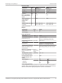
Electrical data
Parameter Unit Value
KN version
Value
KT version
Voltage [V] 100 - 240 100 - 240
Frequency [Hz] 50 / 60 50 / 60
Power P1[W] 25 21
Max. permissible
line voltage fluctu-
ations
[%] ± 10 ± 10
Motor protection
class (DIN EN
60529 / IEC
60529)
IP20 IP20
Rated current con-
sumption
[A] 0.46 / 100V AC
0.24 / 240V AC
0.39 / 100V AC
0.23 / 240V AC
Tab.9 Electrical data
Weight
Pump type Unit Value
N96K_E-W [kg] 0.7
Tab.10 Weight
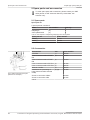
Other parameters
Parameter Unit Value
Permissible ambient
temperature [°C]
[°C / °F] + 5 to see Fig. 1
0 if non-condensing (frost-free)
Permissible media tem-
perature [°C]
[°C / °F] See Fig. 2
Dimensions See Dimensional drawing N96,
Chapter 6.1 Installing the pump
Highest permissible rel-
ative air humidity of the
environment
80% for temperatures up to 31°C,
decreasing linearly to 50% at 40°C.
Maximum installation al-
titude [m above sea
level]
[m / ft
above sea
level]
2000
Gas tightness* of the
pump head (leak rate)
[mbar l/s] < 6 x 10⁻³
Pump protection class
(DIN EN 60529 / IEC
60529)
IP20
Starts against
- Vacuum
- Pressure
KN KT
100
2.5
130
2.5
Tab.11 Other parameters
*The gas tightness of the pump head is no longer ensured after the pump head is
opened or after replacing diaphragms and valve plates. A leak test can be used to
determine whether the original gas tightness has been re-established.

Technical data Diaphragm pump N96_AC
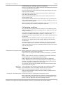
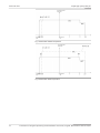
12 Translation of Original Operating and Installation Instruction, english, KNF 329772-329775 09/23
Permissible ambient
temperature
Pressure in
mbar
Pressure in
bar
Fig.1 Permissible ambient temperature
Permissible media
temperature
Pressure in
bar
Pressure in
mbar
Fig.2 Permissible media temperature

Diaphragm pump N96_AC Product description
Translation of Original Operating and Installation Instruction, english, KNF 329772-329775 09/23 13
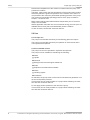
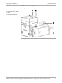
4 Product description
Design
1Pneumatic pump inlet
2Pneumatic pump outlet
3Motor
4Electrical connection
2
1
4
3
Fig.3 Design N96

Product description Diaphragm pump N96_AC
14 Translation of Original Operating and Installation Instruction, english, KNF 329772-329775 09/23
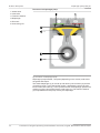
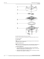
Function of a diaphragm pump
1Outlet valve
2Inlet valve
3Transfer chamber
4Diaphragm
5Eccentric
6Connecting rod
21
4
3
6
5
Fig.4 Function of a diaphragm pump
Diaphragm pumps transfer, compress (depending on the version) and evacu-
ate gases and vapors.
The elastic diaphragm (4) is moved up and down by the eccentric (5) and the
connecting rod (6). In the downwards stroke, it aspirates the gas to be trans-
ferred via the inlet valve (2). In the upwards stroke, the diaphragm presses the
medium out of the pump head via the outlet valve (1). The transfer chamber
(3) is separated from the pump drive by the diaphragm.

Diaphragm pump N96_AC Transport
Translation of Original Operating and Installation Instruction, english, KNF 329772-329775 09/23 15
5 Transport
General
CAUTION
Personal injury and/or property damage due to in-
correct or improper transport of the pump
In the event of incorrect or improper transport, the
pump can fall down, be damaged or injure per-
sons.
àUse suitable auxiliary means if necessary
(carrying strap, lifting gear, etc.).
àWhere appropriate, wear suitable personal
protective equipment (e.g., safety shoes,
safety gloves).
CAUTION
Risk of injury from sharp edges on the packaging
There is a risk of injury from cutting on the sharp
edges when grabbing corners or when opening
the packaging.
àWhere appropriate, wear suitable personal
protective equipment (e.g., safety shoes,
safety gloves).
àTransport the pump in the original packaging to the installation loca-
tion.
àKeep the original packaging of the pump (e.g. for later storage).
àInspect the pump for transport damage after receiving it.
àDocument any transport damage that has occurred.
àRemove any transport safeguards on the pump prior to commissioning.
Parameter
Parameter Value
Storage temperature [°C] + 5 to + 40
Transport temperature [°C] - 10 to + 60
Permissible humidity (non-condens-
ing) [%]
30 to 85
Tab.12 Transport parameters and storage parameters
NOTICE
Prior to commissioning, make sure that the pump
has reached the ambient temperature (3 Techni-
cal data).

Installation and connection Diaphragm pump N96_AC
16 Translation of Original Operating and Installation Instruction, english, KNF 329772-329775 09/23
6 Installation and connection
Only install the pumps in accordance with the operating parameters and
conditions described in Chapter 3 Technical data.
àObserve the safety instructions (see Chapter 2 Safety).
DANGER
Risk of dangerous gas mixtures during pump op-
eration
Depending on the medium being transferred,
breakage of the media-contacting components
can result in a dangerous mixture if the medium
mixes with the air in the compressor housing or
the surroundings.
àBefore using a medium, check the compati-
bility of the media-contacting components
(see 3 Technical data) with the medium.
6.1 Installing the pump
àStore the pump at the installation site to allow it to adapt to the ambient
temperature before installation (condensation must not be allowed to
form).
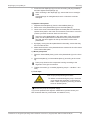
CAUTION
Risk of injury from freely rotating shaft end
Touching the pump at the end of the shaft may re-
sult in injury through burning and crushing.
àTake protective measures to safeguard
against touching moving and hot parts.
àWear appropriate personal protective equip-
ment if necessary.
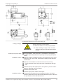
Mounting dimensions àFor mounting dimensions, see the following illustrations:

Diaphragm pump N96_AC Installation and connection
Translation of Original Operating and Installation Instruction, english, KNF 329772-329775 09/23 17
Fig.5 Mounting dimensions of pump series N96K_E-W
Cooling air supply
WARNING
Danger of burning on hot surfaces
Hot surfaces could occur if the pump overheats.
àWhen installing the pump, make sure that
sufficient cooling air infeed and discharge is
ensured.
Proximity to hot pump parts àDuring installation, make sure that no combustible or thermally de-
formable objects are positioned in proximity to hot pump parts (head,
motor).
Installation location àMake sure that the installation location is dry and that the pump is pro-
tected from rain, spray water, splash water, dripping water and other
contaminants.
àMake sure the installation location allows access for servicing.
The IP protection class of the pump motor is specified on the type
plate.
àInstall the pump at the highest point in the system to prevent conden-
sate from collecting in the pump head.
àProtect the pump from dust.
àProtect the pump from vibration and impact.
Installation position àThe pump can be operated in any installation position. Use metal
screws to fasten the pump at the indicated attachment points. Observe
the specifications of the selected fasteners.

Installation and connection Diaphragm pump N96_AC
18 Translation of Original Operating and Installation Instruction, english, KNF 329772-329775 09/23
Protection against foreign
objects
àProtect the pump against contact and the ingress of foreign bodies.
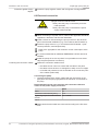
6.2 Electrical connection
DANGER
Danger to life from electric shock
àOnly have the pump connected by an autho-
rized specialist.
àOnly have the pump connected if the power
supply is disconnected.
àWhen connecting to a power source, observe the applicable standards,
regulations, directives, and technical standards.
àInstall a device for disconnecting the pump motor from the electrical
grid in the electrical installation (e.g. in accordance with EN 60335-1).
àProtect the pump motors, e.g. in accordance with EN 60204-1 (over-
current protection, overload protection).
Refer to the type plate for the maximum current consumption of the
pump.
àIt is recommended that an additional EMERGENCY STOP device be
installed.
àInstall the pumps in such a way that it is not possible to touch electri-
cally live parts (electrical connection).
Fastening the connection cables àFasten the connection cables so that
– the cables do not come into contact with movable or hot parts.
– the cables cannot be worn or damaged on sharp corners or edges
– no tensile and pressure forces are exerted on the connection point
of the cables (strain relief)
Connecting the pump
1. Compare the data of the supply voltage with the information on the
type plate. See the pump type plate for the maximum current draw of
the pump.
Recommended current cross sections and connection reference
values for the power supply connection
Value
AWG 18
Conductor cross section [mm2] 0.75
Tightening torque for luster terminal
screws
0.7 – 0.8 Nm
Tab.13
àMake certain that the leads are connected according to the IPC direc-
tives.

Diaphragm pump N96_AC Installation and connection
Translation of Original Operating and Installation Instruction, english, KNF 329772-329775 09/23 19
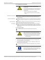
6.3 Pneumatic connection
CAUTION
Personal injury or property damage through
ejected plugs
If not removed, the plugs on the outlet of the pump
can be ejected during operation by the resulting
overpressure.
àRemove the plugs during installation.
àWear appropriate personal protective equip-
ment.
Connected components àOnly connect components to the pump that are designed for the pneu-
matic data and thermal requirements of the pump. (see Chapter 3
Technical data).
Pressure relief device àProtect the compressors by means of a pressure relief device between
the pressure-side connections of the compressor and the first shut-off
valve.
Pump discharge àDischarge the possibly hot pump discharge at the pneumatic outlet of
the pump safely (with regard to medium and noise).
Decoupling àKNF recommends mechanically decoupling the pump from the pipe
system, e.g., through the use of flexible hoses or pipes. In this way it is
possible to prevent the transfer of possible pump vibrations and noises
to the system.
Connecting the pump
A marking on the pump head indicates the flow direction.
CAUTION
Risk of injury due to mixing up inlet and outlet
Mixing up the inlet and outlet may cause breakage
of components connected at the inlet and outlet.
àObserve the marking of inlet and outlet on
the pump head.
1. Remove the protective plugs from the hose connection threads.
2. Connect the suction line and the pressure line (for mounting dimen-
sions, see Chapter 3 Technical data).
3. Lay the suction line and pressure line with a descent so that no con-
densate can run into the pump.
Pneumatic noises can be reduced or dissipated by using a silencer.
NOTICE
Secure the pressure-side connections with a fas-
tener (e.g., hose/pipe clamp) to prevent the hoses
from slipping down from the connection.

Operation Diaphragm pump N96_AC
20 Translation of Original Operating and Installation Instruction, english, KNF 329772-329775 09/23
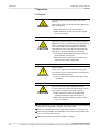
7 Operation
7.1 General
WARNING
Risk of burns from hot pump parts and/or hot
medium
Some pump parts may be hot during or after oper-
ation of the pump.
àAllow the pump to cool after operation.
àTake protective measures to protect against
touching hot parts.
CAUTION
Risk of injury from bursting hoses during pressure
applications due to excessively high temperatures
When operating the pump in pressure applica-
tions, hoses that are not designed for the head
temperatures of the pump at the respective oper-
ating point could become porous and burst.
àUse temperature-resistant pressure hoses at
the pneumatic connections.
àWear protective equipment if necessary (e.g.,
safety gloves, hearing protection).
WARNING
Injury to eyes
Coming too close to the inlet/outlet of the pump
may result in injury to the eyes due to the present
vacuum/operating pressure.
àDo not look into the pump inlet/outlet during
operation.
CAUTION
Risk of injury from freely rotating shaft end
Touching the pump at the end of the shaft may re-
sult in injury through burning and crushing.
àTake protective measures to safeguard
against touching moving and hot parts.
àWear appropriate personal protective equip-
ment if necessary.
àOnly operate the pumps under the operating parameters and operating
conditions as described in Chapter 3 Technical data.
àEnsure the proper use of the pumps (See Chapter 2.6.1 Proper use).
àRule out the possibility of foreseeable misuse of the pumps (see chap-
ter 2.6.2 Foreseeable misuse).
àObserve the safety instructions (Chapter 2 Safety).
La page est en cours de chargement...
La page est en cours de chargement...
La page est en cours de chargement...
La page est en cours de chargement...
La page est en cours de chargement...
La page est en cours de chargement...
La page est en cours de chargement...
La page est en cours de chargement...
La page est en cours de chargement...
La page est en cours de chargement...
La page est en cours de chargement...
La page est en cours de chargement...
-
 1
1
-
 2
2
-
 3
3
-
 4
4
-
 5
5
-
 6
6
-
 7
7
-
 8
8
-
 9
9
-
 10
10
-
 11
11
-
 12
12
-
 13
13
-
 14
14
-
 15
15
-
 16
16
-
 17
17
-
 18
18
-
 19
19
-
 20
20
-
 21
21
-
 22
22
-
 23
23
-
 24
24
-
 25
25
-
 26
26
-
 27
27
-
 28
28
-
 29
29
-
 30
30
-
 31
31
-
 32
32


dans d''autres langues
- English: KNF N 96 Owner's manual
Documents connexes
Autres documents
-
Sera Diaphragm monitoring for ML KM Mode d'emploi
-
Wacker Neuson E3000 Manuel utilisateur
-
-
-
-
 Debem Equaflux 100 Instructions For Use And Maintenance Manual
-
Sames REGULEX 7 - 27 - 47 - 107CC Manuel utilisateur
-
