
INSTALLATION
Référence : SIN-4-2-20
Alimentation : 230V AC ~ 50Hz
Capacité de commutation : 230V AC - 2 x 3A
Consommation : <1W
Puissance Max. : 2 x 690W - Zéro crossing intégré
Protocole radio : Zigbee 3.0
Bande de fréquences utilisée : 2,4Ghz
Puissance radio maximale : +10dBm
Portée : jusqu’à 40m en intérieur
Température de fonctionnement : -20°C à 60°C
Indice de protection : IP 20
Dimensions : 40 mm (l) x 44 mm (L) x 16.9 mm (h)
Poids : 34 g
Garantie : 2 ans
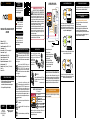
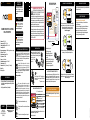
ENTRÉES / SORTIES DU MODULE
Grâce à sa taille réduite, le Module
Éclairage ON/OFF Zigbee peut être
monté n’importe où dans le mur ou le
plafond (derrière un
interrupteur filaire
existant, dans un
faux plafond, etc…).
Chaque borne doit être raccordée par un câble de section
comprise entre 1.5mm² et 4mm² dénudé de 8mm.
*Interrupteur laire en option
nodon.fr/ section “support”
NodOn SAS
121 rue des Hêtres
45590 St CYR EN VAL
(FRANCE)
CONTACT SAV
MODE D’EMPLOIFR
MODULE ÉCLAIRAGE ON/OFF
ZIGBEE
Ajoutez le Module Éclairage ON/OFF Zigbee
au tableau électrique avec le Boitier Rail
DIN* NodOn. *Accessoire en option
Le produit est utilisé à 20 cm ou plus du corps
humain.
Ce produit est conforme au protocole radio Zigbee.
Ce produit est prévu pour être utilisé en intérieur
uniquement.
La présence de ce symbole sur un produit
indique que ce dernier est conforme à la directive
européenne 2012/19/UE. Renseignez-vous sur
les dispositions en vigueur dans votre région
concernant la collecte séparée des appareils électriques et
électroniques. Respectez les réglementations locales et ne
jetez pas le produit avec les ordures ménagères ordinaires. La
mise au rebut correcte d’anciens produits permet de préserver
l’environnement et la santé.
Par la présente, NodOn SAS déclare que cet équipement
radio est conforme à la directive RED 2014/53/UE.
Le texte intégral de la déclaration de conformité
de l’UE est disponible à l’adresse Internet suivante : nodon.fr/
section «Support»
APPROBATIONS ET CERTIFICATIONS
Retrouvez tous les schémas de câblage sur la rubrique
“Support” sur nodon.fr/
PRÉCAUTIONS D’USAGES
• N’utilisez jamais l’appareil s’il n’est pas correctement
installé et placé à l’intérieur d’une boite de
raccordement conforme aux normes en vigueur.
• Tenez le produit éloigné de tous liquides.
SCHÉMAS DE CÂBLAGE
DANGER D’ÉLECTROCUTION
AVANT T O U T E I N S TA L L AT ION ASSUREZ-
VOUS D’AVOIR COUPÉ L’ ALIMENTATION
ÉLECTRIQUE SOUS PEINE D’ÉLECTROCUTION.
Coupez directement l’alimentation depuis le coffret
électrique, pour éviter tout risque d’électrocution. Ce module
est conçu pour une utilisation sous tension, une mauvaise
installation peut entraîner un incendie ou un choc électrique.
Si vous ne vous sentez pas à l’aise avec les installations
électriques, veuillez consulter un professionnel.
Le module doit obligatoirement être installé ET connecté en
suivant scrupuleusement les instructions de cette notice.
Nous ne pourrons être tenus pour responsables en cas
d’accident ou de dommages dus au non respect des
instructions de montage.
Coupez l’alimentation avant toute intervention et n’effectuez
aucune modication si la LED est allumée.
NEntrée Neutre
LEntrée Phase
Entrée pour
l’interrupteur laire 1*
Entrée pour
l’interrupteur laire 2*
Sortie 1 (contrôlée par )
Sortie 2 (contrôlée par )
PROCÉDURE DE RÉINITIALISATION
DU MODULE
AJOUT AU RÉSEAU ZIGBEE
Lors de la mise sous tension, la Led du module clignote en
orange cherchant à joindre un réseau Zigbee. Rendez-vous
dans l’application de votre centrale Zigbee pour activer la
détection du module. Voir la liste des centrales domotiques
compatibles sur nodon.fr/support/
Si le module a correctement rejoint le réseau, la Led devient
verte. Le module est prêt à être utilisé.
Si module n’a pas rejoint un réseau dans les 15 minutes,
la Led devient orange. Faites un appui rapide sur le bouton
du module et recommencez la procédure.
Le module doit être raccordé et sous tension.
1 Appuyez plus de 5 secondes sur le bouton du module.
La LED scintille en orange.
2 Appuyez à nouveau sur le bouton (impulsion brève)
pour valider la réinitialisation. Si la réinitialisation se déroule
correctement, la LED clignote alternativement en rouge
et en vert, puis clignote en orange. Recommencez si nécessaire.
3 Votre module a retrouvé sa conguration d’origine et est
prêt a rejoindre un nouveau réseau Zigbee.
DÉSAPPAIRAGE DU MODULE
Pour supprimer le module de son réseau, faites un Reset du
module (voir “procédure de réinitialisation du Module”).
Accédez directement à la notice
détaillée sur la rubrique support
sur nodon.fr/support/
NOTICE
DÉTAILLÉE
INSTRUCCIONES
DE USO
GEBRAUCHSANWEISUNG
Acceda directamente
a las instrucciones
detalladas en la página de soporte
de nodon.fr/es/soporte/
Gehen Sie direkt zur
ausführlichen Anleitung
im Support Bereich unter
nodon.fr/de/technische-
unterstuetzung/
Par la présente, NodOn SAS déclare que cet
équipement radio est conforme à la directive
RER 2017 (SI 2017/1206). Le texte intégral
de la déclaration de conformité du Royaume-
Uni est disponible à l’adresse internet suivante : nodon.fr/
section «Support».
SCHÉMA D’INSTALLATION
POUR UNE OU DEUX LAMPES
Câblage à une ou deux voies
*Interrupteur laire en option.
*
1 Coupez le courant.
2 Démontez l’interrupteur laire qui
pilote la/les éclairage(s) que vous
souhaitez raccorder.
3 Câblez le Module Éclairage
ON/OFF selon le schéma en gure 1.
4 Remontez l'interrupteur laire.
5 Remettez le courant.
Figure 1
AUTO-DÉTECTION DU TYPE D’INTERRUPTEUR
Lorsque que vous allumez l’alimentation électrique (via le
coffret électrique par exemple) une fois le module installé, il est
nécessaire de faire une action simple (Un appui unique) sur le(s)
interrupteur(s) filaire(s). Une détection automatique du type
d’interrupteur (Monostable ou bistable) sera alors effectuée.
ASTUCE
Adresse de l’importateur au Royaume-Uni :
xxx
xxx

Each terminal should be installed with a cable from 1.5mm² to
4mm² maximum, stripped of 8mm.
*Wired switch optional.
NTerminal for the Neutral
LTerminal for the Line
Input terminal
for the wired switch 1*
Input terminal
for the wired switch 2*
Output 1 (controlled by )
Output 2 (controlled by )
INSTALLATION DIAGRAM
FOR ONE OR TWO LIGHTS
Wiring with one or two ways
*Wired switch optional.
*
1 Cut the power supply
2 Dismantle the wired switch
controlling the light(s) you want
to connect.
3 Install the ON/OFF Lighting Relay
Switch according to diagram gure 1.
4 Reinstall the wired switch.
5 Turn the power supply back ON.
Figure 1
INSTALLATION
RELAY SWITCH INPUT/OUTPUT
nodon.fr/en/ “support” section
NodOn SAS
121 rue des Hêtres
45590 St CYR EN VAL
(FRANCE)
CONTACT AFTER-SALES SERVICE
USER GUIDEEN
The device is used 20 cm or more from the human
body.
This product is conform to Zigbee radio protocol.
This product must be used indoor only.
The presence of this symbol on a product
indicates that this one is conform to the
European directive 2012/19/UE. Find out
more about the provisions in force in your
region regarding the separate collection of electrical and
electronical devices. Respect the local rules and do not
throw out the product with common domestic wastes. The
correct rejection of ancient products allows to preserve
the environment and health.
Hereby, NodOn SAS declares that this radio
equipment is conform to the RED directive
2014/53/UE. The integral text of the EU declaration
of conformity is available at the following online address:
nodon.fr/en/ ”support” section.
APPROVALS AND CERTIFICATIONS
USE CAUTIONS
• Never use the device if it is not correctly installed and
placed inside a connecting box in conformity with the
current norms.
• Keep the product far away from liquids.
DANGER OF ELECTROCUTION
BEFORE ANY INSTALLATION MAKE SURE THE
POWER SUPPLY IS DISCONNECTED TO AVOID
ANY RISK OF ELECTROCUTION.
Directly cut the power supply from the breaker box to avoid
any risk of electrocution. This relay switch is designed to
be used power up, a wrong installation can create a re or
an electric shock. If you are not condent about electrical
installation, please ask a professional.
The relay switch must be installed and connected carefully
following the instructions of this user guide. We will not be
responsible for any loss or damage resulting from a non-
respect of the instructions of this user guide. Cut the power
supply before any operation and don’t do any modication
if the LED is still ON.
Reference: SIN-4-2-20
Power supply: 230V AC ~ 50Hz
Switching capabilities: 230V AC - 2 x 3A
Consumption: <1W
Maximum output power: 2 x 690W - Integrated zero crossing
RF Protocol: Zigbee 3.0
Radio frequency range: 2.4Ghz
RF power max: +10dBm
Range: up to 40m indoor
Operational temperature: -20°C to 60°C
Protection rating: IP 20
Dimensions: 40 mm (l) x 44 mm (L) x 16.9 mm (h)
Weight: 34 g
Warranty: 2 years
ZIGBEE ON/OFF LIGHTING
RELAY SWITCH
Add the Zigbee ON/OFF Lighting Relay
Switch to the electric panel with NodOn
DIN Rail Box*.*Optional accessory
Find all the installation diagrams on the “Support” section on
nodon.fr/en/
INSTALLATION DIAGRAMS
TIP
SIN-4-2-20_UG_V6
Thanks to its small size, the Zigbee ON/
OFF Lighting Relay Switch can be installed
anywhere in the wall or the ceiling (behind
an existing wall
switch, in a false
ceiling, etc…).
RESET PROCEDURE
Relay switch must be power supplied.
1 Press more than 5 seconds on your module’s button.
The Led blinks orange.
2 Press the button again (short press) to validate the reset.
If the reset is successful, the Led flashes red and green
alternately, then flashes orange. Repeat if necessary.
3 Your module has returned to its original conguration
and is ready to join a new Zigbee network.
UNPAIRING PROCEDURE
To remove the module from its network, perform a Module Reset
(see “Reset Procedure”).
ADDING TO A ZIGBEE NETWORK
When power is turned ON, the relay switch Led will blink
orange, looking to join a Zigbee network. Go to your Zigbee
gateway app to activate the relay switch detection.
See the compatible home automation gateways on
nodon.fr/en/support/
If the relay switch has correctly joined the network, the Led
becomes green. The relay switch is ready for use.
If the relay switch hasn’t joined a network within 15 minutes,
the Led becomes orange. Do a brief press on the relay switch
button and start again.
Directly access the detailed user
guide on the Support section
on nodon.fr/en/technical-
support/
DETAILED
USER GUIDE
INSTRUCCIONES
DE USO
GEBRAUCHSANWEISUNG
Acceda directamente
a las instrucciones
detalladas en la página de soporte
de nodon.fr/es/soporte/
Gehen Sie direkt zur
ausführlichen Anleitung
im Support Bereich unter
nodon.fr/de/technische-
unterstuetzung/
AUTO-DETECTION OF SWITCH TYPE
When you turn the power supply ON (via the electrical box for
example) once the relay switch is installed, it is necessary to
perform a simple action (single press on the button) on the
wired switch(es). Automatic detection of the type of switch
(monostable or bistable) will then be performed.
Hereby, NodOn declares that the radio
equipment type direct current motor
controller is in compliance with RER 2017
(SI 2017/1206). The full text of the UK declaration
of conformity is available at the following internet address:
nodon.fr/en/ ”support” section..
UK importer address:
xxx
xxx
-
 1
1
-
 2
2


