
BATTERY SWEEPER
Operator’s Manual (EN)
Manual del operario (ES)
Manuel de l’opérateur (FR)
Model Part No.:
1251274 - Sweeper [Scout 7]
To view, print or download
the parts manual, visit:
www.nobles.com/manuals
www.nobles.com PLDC04332
Rev. 05 (03-2022)
SCOUT 7
TM

EN TRANSLATION OF ORIGINAL INSTRUCTIONS
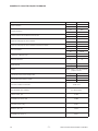
TECHNICAL DATA AND CHARACTERISTICS ......................................................................................................2
WARNINGS ..............................................................................................................................................................3
SAFETY MEASURES ..............................................................................................................................................3
SAFETY LABELS ....................................................................................................................................................4
SERIAL NUMBER LABEL LOCATION ...................................................................................................................5
INTRODUCTION ......................................................................................................................................................5
UNPACKING ............................................................................................................................................................5
PREPARING THE MACHINE ..................................................................................................................................5
Fitting the side brush ...................................................................................................................................5
Fitting the handle ..........................................................................................................................................5
Preparation, installation and replacement of the battery .........................................................................6
ADJUSTMENT CONTROLS ....................................................................................................................................6
START-UP ................................................................................................................................................................6
INSTRUCTIONS FOR CORRECT OPERATION .....................................................................................................7
TAKING OUT THE DEBRIS HOPPER FOR CLEANING .......................................................................................7
)URQWELQ¿J ............................................................................................................................................7
5HDUELQ)LJ .............................................................................................................................................7
ROUTINE MAINTENANCE ......................................................................................................................................7
BATTERY MAINTENANCE .....................................................................................................................................8
Recharging the battery .................................................................................................................................8
BATTERY CHARGER SETTINGS ...........................................................................................................................8
BATTERY CHARGER ANOMALIES .......................................................................................................................8
FILTER MAINTENANCE ..........................................................................................................................................9
&OHDQLQJWKHSUH¿OWHU ...................................................................................................................................9
&OHDQLQJWKH¿OWHU .........................................................................................................................................9
5HSODFLQJWKH¿OWHU .......................................................................................................................................9
REPLACING AND ADJUSTING THE SIDE BRUSH ...............................................................................................9
REPLACING AND ADJUSTING THE CENTRE BRUSH ........................................................................................9
REPLACING AND ADJUSTING THE BELT ............................................................................................................10
Replacing the side brush belt ......................................................................................................................10
Replacing the drive belt ...............................................................................................................................10
REPLACING THE FLAPS .......................................................................................................................................10
2XWHUVLGHÀDSV .............................................................................................................................................10
,QQHUVLGHÀDSV .............................................................................................................................................10
&HQWUHÀDS .....................................................................................................................................................10
REPLACING AND ADJUSTING THE CABLES ......................................................................................................11
Replacing the drive cable ............................................................................................................................11
Replacing the side brush lifting cable ........................................................................................................11
CIRCUIT BRAKERS ................................................................................................................................................11
TROUBLESHOOTING TABLE ................................................................................................................................11
SCRAPPING THE MACHINE ..................................................................................................................................12
RECOMMENDED SPARE PARTS LIST ..................................................................................................................12
TABLE OF CONTENTS
Copyright © 2019 Tennant Company. All rights reserved.
Tennant Company
10400 Clean Street
Eden Prairie, MN 55344-2650
Phone: (800) 553- 8033
www.tennantco.com
- 1 -

EN TRANSLATION OF ORIGINAL INSTRUCTIONS
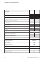
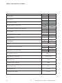
TECHNICAL DATA AND CHARACTERISTICS
DESCRIPTION
Maximum width mm 740
inches 29
Maximum length mm 1245
inches 49
Maximum height clearance with handle mm 960
inches 37.75
Cleaning width with centre brush mm 500
inches 19.68
Cleaning width with centre brush and side brush mm 700
inches 28
Weight with battery kg 121
lbs 266.76
Front debris bin capacity l45
ft31.6
Operating autonomy h<3
Filtering area m² 1.03
ft211.08
Filtration HႈFLHQW IRU SDUWLFOHV XS WR
microns
Productivity (for Hour) Theoretically Max. m2/h 2601
ft2/h 28000
Productivity (for Hour) Estimate Coverage m2/h 2508
ft2/h 27000
Installed power / current 710W / 59A
Battery type (maintenance-free) 12V 140Ah (C20)
Sound pressure, LpA 70 dBA
Measurement uncertainty, kpA 3.0 dBA
Sound power, LwA,g 80 dB
Vibration level (hand), ahv 1.1 m/sec2
Measurement uncertainty, k 0.5 m/sec2
- 2 -

EN TRANSLATION OF ORIGINAL INSTRUCTIONS
WARNINGS
This machine is intended for commercial use only. Its intended
purpose is to collect dirt, dry waste and dust from dry, paved or
carpeted surfaces.
It must not be used for any other purposes. Do not use the machine
to pick up liquids, hazardous or toxic materials.
Operators are required to read, understand and comply with the
following warnings.
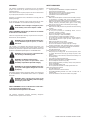
In this manual, the warning symbol shown below and the term
“SAFETY WARNING” are used with the following meanings:
WARNING: warns of dangers or dangerous proce-
dures that may cause serious injuries or death.
SAFETY WARNING: indicates the procedures to be followed
for the safe use of the machine.
Failure to comply with these warnings may be the cause of injuries,
HOHFWULFVKRFN¿UHRUH[SORVLRQV
WARNING: Do not operate the machine in the pres-
HQFHRIÀDPPDEOHOLTXLGVRUYDSRXUVRUFRPEXV-
tible dusts.
The machine is not equipped with explosion-proof motors. The
sparks generated in the electric motors when starting and during
RSHUDWLRQPD\FDXVH¿UHRUH[SORVLRQLIWKHPDFKLQHLVXVHGLQWKH
SUHVHQFHRIÀDPPDEOHOLTXLGVYDSRXUVRUFRPEXVWLEOHGXVWV
:$51,1*'RQRWSLFNXSWR[LFRUÀDPPDEOHPDWH-
rials, burning or smouldering waste.
WARNING: The batteries emit hydrogen.
.HHS DZD\ IURP VSDUNV DQG RSHQ ÀDPHV /HDYH
the battery compartment open while charging.
WARNING: Do not charge the batteries if the char-
ger’s power cable appears damaged. Do not mod-
ify the plug.
If the battery charger cable is damaged or broken, have it replaced
E\WKHPDQXIDFWXUHUDQDXWKRULVHGVHUYLFHFHQWUH RUDTXDOL¿HG
technician.
WARNING: Before carrying out any work on the
machine, disconnect the battery cables and unplug
the charger’s power cable.
SAFETY WARNINGS: Do not use the machine on wet surfac-
es. Do not expose the machine to rain.
The machine must be kept indoors at all times
The following information indicates potentially dangerous
conditions for the operator or the machine.
SAFETY MEASURES
Do not use the machine:
• ,QWKHSUHVHQFHRIÀDPPDEOHRUH[SORVLYHVXEVWDQFHV
• Unless trained and authorised.
• Without having read the operator manual carefully.
• If the machine is not in perfect conditions.
• ,QWKHDEVHQFHRIDELQDQGRU¿OWHUV
Battery charger;
• Make sure that the power socket used for the battery charger
is connected to a suitable earth system and protected by
thermal overload and residual current circuit breakers.
• Make sure the electrical characteristics of the battery charger
(voltage, frequency, absorbed power) given on the rating
plate are the same as those of the mains power supply.
Before starting the machine:
• Make sure the safety devices are present and are functioning
correctly.
When the machine is running:
• Do not pick up burning or smouldering waste, such as
cigarettes, matches or embers.
• Do not use the machine to pick up liquids.
• Report any damage or faults immediately.
• Proceed slowly on sloping and slippery surfaces.
• Do not leave the machine unattended or on sloping surfaces.
• Do not use the machine to pick up wires, ropes, straps or
similar materials.
• Make sure the work area is well lit.
• Keep the machine out of the reach of children.
• Do not use the machine to transport people or things.
• In dusty environments, wear protective glasses and gloves.
Before leaving the machine or before carrying out maintenance:
• 6WRSWKHPDFKLQHRQÀDWDQGGU\ÀRRULQJ
• 7XUQWKHPDFKLQHRႇ
During maintenance and repair work:
• Keep away from moving parts. Do not wear jackets, shirts
or clothes with sleeves that may get caught in parts of the
machine.
• Before working on the machine, disconnect the battery and
the charger plug.
• Use original or approved spare parts.
• 5HSDLUVPXVWEHSHUIRUPHGE\DTXDOL¿HGWHFKQLFLDQ
• Do not modify the machine in any way.
• When handling the battery or battery cables, wear protective
gloves and goggles.
• Avoid contact with battery acid.
• Do not operate the machine on slopes greater than 2%
When transporting the machine:
• 7XUQWKHPDFKLQHRႇ
• Request assistance to lift the machine.
• )RU ORDGLQJXQORDGLQJ RQWRRႇ RI D WUXFN RU WUDLOHU XVH D
suitable ramp.
• Secure the machine to the truck or trailer using straps.
- 3 -

EN TRANSLATION OF ORIGINAL INSTRUCTIONS
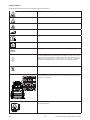
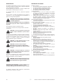
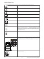
SAFETY LABELS
6DIHW\ODEHOVDUHDႈ[HGWRWKHPDFKLQH,IGDPDJHGWKHVHPXVWEHUHSODFHG
WARNING! RISK OF ENTANGLEMENT
WARNING! RISK OF ACID BURNS
WARNING! RISK OF BURNS
MAXIMUM SLOPE
OPERATOR MANUAL, INSTRUCTIONS FOR USE
READ THE OPERATOR'S MANUAL
DIRECT CURRENT SYMBOL
CLASS III APPLIANCE. AN APPLIANCE IS IDENTIFIED AS CLASS III WHEN
ITS EXPLOSION-PROOF PROTECTION IS BASED ON THE FACT THAT
THERE ARE NO VOLTAGES HIGHER THAN THE ULTRA-LOW SAFETY
EXTRA-LOW VOLTAGE (SELV). THIS MEANS IN PRACTICE THAT THE
APPLIANCE IS POWERED BY A BATTERY OR A SELV TRANSFORMER.
SPECIAL WASTE. DO NOT DISPOSE OF AS NORMAL WASTE.
SAFETY LABEL. THE SAFETY LABEL APPEARS ON THE MACHINE IN THE
LOCATION INDICATED. REPLACE LABEL IF IT IS MISSING OR IF IT BECOMES
DAMAGED OR ILLEGIBLE.
WARNING! RISK OF ABRASION OR ENTANGLEMENT BY TOUCHING THE
BRUSH IN ROTATION
- 4 -

EN TRANSLATION OF ORIGINAL INSTRUCTIONS
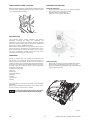
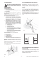
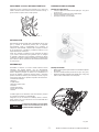
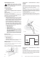
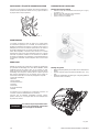
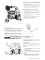
SERIAL NUMBER LABEL LOCATION
Make sure that the machine is equipped with a rating plate showing
WKHVHULDOQXPEHUSRVLWLRQHGDVVKRZQLQ¿J,IWKLVLVQRWWKH
case, notify the dealer immediately.
PREPARING THE MACHINE
Fitting the side brush
• Move the brush raising lever (pos. 1 Fig. 3) to the “0” position..
• Unscrew the screw on the side brush shaft.
• Place the brush on the shaft (Fig. 2).
• Tighten the screw complete with washer.
INTRODUCTION
This instruction manual contains guidelines and practical
information concerning the safety, use, adjustment and
maintenance of the machine. The machine has been designed
DQGEXLOWWRRႇHU WKHEHVWLQWHUPVRI SHUIRUPDQFHFRPIRUW DQG
HDVHRIXVHLQDYDULHW\RIGLႇHUHQWFRQGLWLRQV
Before delivery, the machine has been checked at our factory
and by our dealer to guarantee that it is handed over to you in
perfect working order. To maintain the machine in this condition
and ensure problem-free operation, strictly follow the routine
maintenance instructions given in the manual.
UNPACKING
Unpack the machine with care, avoiding any manoeuvres that
may damage it; once unpacked, check that all of the parts are
intact. If you notice any damage, DO NOT use the machine and
contact your dealer. Due to packaging and transport requirements,
some parts and optionals may be supplied separately; for correct
assembly, follow the instructions given in the corresponding
paragraphs of this booklet.
Contents of the packaging:
1 Machine
1 Side brush
1 Instruction booklet
1 Warranty
1 Tool kit:
2 Ignition keys
1 Battery
If you notice that any of the above are missing, contact the dealer
immediately.
Make sure the packaging materials (bags, boxes, pallets, hooks,
etc.) are put away, out of the reach of children.
To avoid losing them during transport, the ignition
keys are placed inside the document envelope.
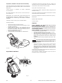
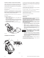
Fitting the handle
• 5HPRYHWKHWRSFRZOLQJWRDFFHVVWKHKDQGOH¿[LQJVFUHZV
• Lift the handle to the operating position (pos. 1 Fig. 2/A).
• 7LJKWHQWKHKDQGOH¿[LQJVFUHZVSRV)LJ$XVHWKHWRRO
supplied with the machine).
NOTES
FIG. 1
Fig. 2
Fig. 2/A
12
- 5 -

EN TRANSLATION OF ORIGINAL INSTRUCTIONS
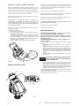
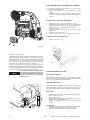
Preparation, installation and replacement of the battery
FOR YOUR SAFETY: Wear protective gloves and eye protection
when handling the battery and battery cables. Avoid contact with
battery acid.
Contact Tennant or distributor for battery replacement
recommendations.
Max. battery dimensions: 18 cm (7.00 in) P x 32 cm (12.50 in) L x
24 cm (9.38 in ) H.
IMPORTANT: The on-board battery charger settings MUST BE
UHFRQ¿JXUHG ZKHQ FKDQJLQJ WR D GLႇHUHQW W\SH RI EDWWHU\ LH
LIQUID (lead-acid) or SEALED (gel). See BATTERY CHARGER
SETTINGS
The battery charger is factory-set for Gel/AGM batteries.
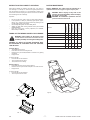
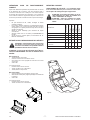
Installing the battery:
• Remove the ignition key from the machine.
• Turn the front cowling and remove the top cowling to access
the battery compartment.
• Carefully place the battery in the compartment with the
battery terminal facing the rear of the machine and connect
the cables to the battery: RED to the POSITIVE pole (+),
BLACK to the NEGATIVE (-) (Fig 2/B).
• Secure the battery with the strap.
• Charge the battery. See RECHARGING THE BATTERY
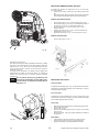
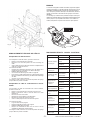
ADJUSTMENT CONTROLS
1) Side brush control lever: moving the lever to “I” position, the
side brush moves to the working position and starts rotating. To
stop the brush, return the lever to the “0” position.
2) Key switch: machine power supply.
3) Charge status indicator: displays the battery charge when the
machine is running.
4) Drive lever: pulling this lever engages the transmission and the
machine that starts to move forward.
5) Flap lever: pulling this lever allows the centre brush to pick up
bulky objects.
(OHFWULF¿OWHUVKDNHUEXWWRQ
7) Suction switch.
START-UP
SAFETY WARNINGS: The machine must only be used by
trained and authorised personnel.
'RQRWSLFNXSOLTXLGVRUOHDYHWKHPDFKLQHXQDWWHQGHG5H-
move the ignition key before leaving the machine and keep it
out of the reach of children.
SAFETY WARNING: Do not use the machine on wet surfaces.
To start the machine, proceed as follows:
• Check that the side brush pos. 1 Fig 3 is in the “0” position.
• Turn the key switch to “I” position, pos. 2 Fig. 3.
• After turning the key, wait about 10 seconds until the machine
starts running. Check on the indicator pos. 3 Fig. 3 that the
battery is fully charged before starting work, otherwise charge
the battery.
• Activate the suction motor by moving the switch in pos. 7 Fig.
3 to “I”.
7XUQRႇWKHVXFWLRQPRWRUZKHQXVLQJWKHPDFKLQH
when being moved by moving the switch in pos. 7
Fig. 3 to “0”.
• Pull the drive lever pos. 4 Fig. 3 and carry out the cleaning
operations. If necessary, operate the lever pos. 1 Fig. 3,
moving it to position “I” to engage the side brush. After having
¿QLVKHGZRUNPRYHWKHVLGHEUXVKOHYHULIXVHGWRSRVLWLRQ
³´ VZLWFK WKH PDFKLQH Rႇ DQG UHPRYH WKH NH\V IURP WKH
control panel.
An automatic device prevents the machine from working beyond a
certain battery discharge threshold.
Once this limit is reached, the machine stops and must be
recharged in order to resume operation.
NOTES
Fig. 2/B
1
5
26-7
3
4
Fig. 3
- 6 -

EN TRANSLATION OF ORIGINAL INSTRUCTIONS
INSTRUCTIONS FOR CORRECT OPERATION
$IWHU KDYLQJ VWDUWHG WKH PDFKLQH WKH ¿UVW WLPH LW LV UHDG\ WR
start working as a sweeper. To achieve the highest performance
from the sweeper at all times, it is recommended to follow some
instructions aimed at keeping the machine in the best conditions
and minimising the risk of damage.
Important:
• Do not pick up wires, ropes, straps or other similar materials.
• In the presence of bulky or particularly light objects (paper,
leaves, etc.), raise the front of the machine by pushing on the
handle while picking up the waste.
• 8VHWKHÀDSUDLVLQJOHYHUWRFROOHFWEXON\LWHPV
• 6KDNH WKH ¿OWHU DIWHU KDYLQJ ¿QLVKHG ZRUN VHH ),/7(5
MAINTENANCE).
• Keep the centre brush correctly adjusted (see CENTRE
BRUSH ADJUSTMENT).
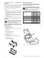
TAKING OUT THE DEBRIS HOPPER FOR CLEANING
WARNING: Before taking out the hopper, make
VXUHDOOPDFKLQHIXQFWLRQVDUHWXUQHGRႇ7KLVLVWR
avoid the possibility of touching the rotating brush.
WARNING: ALL WASTE COLLECTION OPERATIONS MUST
BE PERFORMED IN COMPLIANCE WITH THE RELEVANT
LAWS IN FORCE.
)URQWELQ¿J
• Turn/open the front cover.
• Lift and turn the two bin locking devices.
• Hold the bin by the handle/handles and remove it by pulling
it upwards.
• Empty the bin.
To replace the bin:
• Insert the bin into the machine.
• Turn and lower the two locks.
• Turn/close the front cowling.
5HDUELQ)LJ
• Lift and turn the two rear bin locking devices.
• Hold the rear bin by the handle and pull it out of the machine.
• Empty the bin.
To replace the bin:
• Insert the bin into the machine.
• Turn and press the two locks.
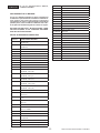
ROUTINE MAINTENANCE
SAFETY WARNINGS: Any repairs must be performed by a
TXDOL¿HGWHFKQLFLDQ8VHRULJLQDORUDSSURYHGVSDUHSDUWV
WARNING: Before carrying out any work on the
machine, disconnect the battery cables and unplug
the charger’s power cable.
WARNING: All maintenance operations must be
SHUIRUPHGZLWKWKHPDFKLQHRႇ
CHECKS
On delivery
Every 10 hours
Every 50 hours
Every 100 hours
Every 200 hours
Loosening of belts X
Tightness of the nuts and screws X
Conditions of the brushes X
Check tightness of the gaskets X
Check that all functions are active XXXX
5HSODFHWKH¿OWHU X
Fig. 4
FIG. 5
Fig. 5/A
- 7 -

EN TRANSLATION OF ORIGINAL INSTRUCTIONS
BATTERY MAINTENANCE
The battery must always be kept clean and dry. Terminals and
poles must be kept clean at all times. Liquid battery (lead-acid),
every 10 hours remove the caps and check the electrolyte level;
if necessary top up with distilled water to cover the plates, do not
RYHU¿OO PD[LPXP PP DERYH WKH SODWHV 5HPHPEHU WKDW WKH
room where this operation is carried out must be well ventilated;
NHHSDZD\IURPQDNHGÀDPHVGRQRWVPRNHGXULQJWKLVRSHUDWLRQ
The battery has an operating time that should exceed 2 hours; if
this turns out to be considerably shorter, check:
• that the brushes are not blocked by wires, ropes and straps;
• that the battery has been fully recharged.
Recharging the battery
Battery life depends on routine maintenance and the level of
discharge. Do not let the battery charge fall below the limit
indicated by the lights in pos. 3 Fig. 3.
Once the max. discharge limit has been reached, the machine will
stop and must be recharged before it can be used again.
Charge lights on the control panel
Green light: The battery is charged.
Yellow light: The battery is discharging; recharge as soon as
possible.
Red light: The battery is discharged. DO NOT continue using the
machine, recharge it immediately.
To recharge the battery
WARNING: The batteries emit hydrogen. Keep
DZD\IURPVSDUNVDQGQDNHGÀDPHV/HDYHWKHEDW-
tery compartment open while charging.
SAFETY WARNINGS: Avoid contact with the battery acid dur-
ing maintenance and repair operations. When handling the
battery or battery cables, wear protective gloves and goggles.
• When not in use, keep the machine in a well-ventilated place.
• :KHQ WKH PDFKLQH LV Rႇ FRQQHFW WKH FKDUJHU FDEOH )LJ
$&KHFN WKDW WKHLQSXWYROWDJH VSHFL¿HG IRUWKH EDWWHU\
charger is compatible with the available power supply voltage.
• Before recharging, make sure that the charger settings
are correct. The battery charger is factory-set for Gel/AGM
batteries. (See BATTERY CHARGER SETTINGS).
• If there is a problem with the battery charger, an error code
will be displayed (see the manual for the battery charger
supplied with the machine).
• During the charging cycle, the charger lights will change
FRORXUIURPUHGWR\HOORZDQG¿QDOO\JUHHQ$WWKHHQGRIWKH
charging cycle, when the green light is on, disconnect the
charger cable.
WARNING: Never disconnect the battery when re-
charging. This may cause sparks.
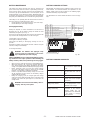
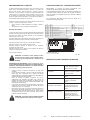
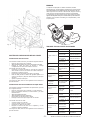
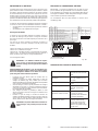
BATTERY CHARGER SETTINGS
IMPORTANT: The battery charger supplied is factory-set for Gel/
AGM batteries. For lead-acid batteries, the dipswitches on the
EDWWHU\ FKDUJHU PXVW EH VHW DV VKRZQ LQ WKH IROORZLQJ ¿JXUH
otherwise the battery may be damaged.
The dipswitches are located behind the black round cover (Fig.
5/B).
BATTERY CHARGER ANOMALIES
<HOORZ/('ÀDVKLQJ Unsuitable battery or battery
not connected or output short
circuit.
5HGDQG<HOORZ/('ÀDVKLQJ Battery voltage higher than
4.0V but lower than 1.4V for
Cell.
Red and Green LED ON Internal overtemperature error.
5HG/('ÀDVKLQJ Safety timer exceeded.
Internal short circuit (Output
overcurrent)
Red, Yellow and Green LED
ÀDVKLQJHYHU\VHFRQG
$OOFKDUJLQJSUR¿OHSDUDPHWHUV
are not programmed to the
EEPROM of the charger.
Red, Yellow and Green LED
ÀDVKLQJFRQWLQXRXVO\
7KH FKDUJLQJ SUR¿OH
parameters of the selected
FKDUJLQJ SUR¿OH DUH QRW
programmed to the EEPROM
of the charger or charging
SUR¿OHQRWDFWLYH
SW2
DP2
ON 13A DEFAULT
OFF 10A
SW1 SW2
DP1 DP2 DP1
OFF OFF OFF IUIa Acido generica
OFF OFF ON IUIa/O Acido generica con mant.
OFF ON OFF IUIa Acido "Trojan"
OFF ON ON IUUO Gel/AGM Generica DEFAULT
ON OFF OFF IUIa Gel "Exide Sonnenschin"
ON OFF ON IUIa AGM "Discover"
ON ON OFF IUIa Gel AGM Reliant AGM "Trojan"
ON ON ON IUoU AGM Fullriver
DIP- SWITCH (SW1-SW2)
ON ON
OFF OFF
DP1 DP2
SW1
ON ON
OFF OFF
DP1 DP2
SW2 ON
Fig. 5/B
- 8 -

EN TRANSLATION OF ORIGINAL INSTRUCTIONS
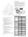
FILTER MAINTENANCE
:$51,1*%HIRUHWDNLQJRXWWKHGXVW¿OWHURUSUH
¿OWHUPDNHVXUHDOOPDFKLQHIXQFWLRQVDUHWXUQHG
Rႇ7KLVLVWRDYRLGWKHSRVVLELOLW\RIWRXFKLQJWKH
rotating brush.
&OHDQLQJWKHSUH¿OWHU
&OHDQWKHSUH¿OWHUHYHU\GD\
• Remove the rear bin
• 5HPRYHWKHSUH¿OWHUIURPWKH¿OWHU
• &OHDQWKHSUH¿OWHUZLWKDYDFXXPFOHDQHURUZDVKLWXQGHU
running water and allow it to dry completely before replacing
it in the machine.
&OHDQLQJWKH¿OWHU
7KHVXFWLRQ¿OWHUPDNHVDPDMRUFRQWULEXWLRQWRWKHHႈFLHQF\RI
the whole machine.
3URSHU ¿OWHU PDLQWHQDQFH ZLOO DOORZ \RX WR REWDLQ WKH EHVW
performance from your machine. If the sweeper begins to raise
GXVWDVLWVZHHSVFKHFNWKHFRQGLWLRQRIWKHVXFWLRQ¿OWHU
7KHVXFWLRQ¿OWHUFDQEHFOHDQHGDVIROORZV
• DXWRPDWLF¿OWHUFOHDQLQJKROGWKH¿OWHUVKDNHUEXWWRQSRV
Fig. 3 in position “II” for a few seconds. Repeat this operation
while using the machine. This operation should be performed
at the end of every working cycle. If the machine is used
in a dusty environment (e.g. sawmills, warehouses where
YHKLFOHV RSHUDWH HWF PDNH VXUH WR XVH WKH ¿OWHU VKDNHU
more frequently.
• PDQXDOO\FOHDQLQJWKH¿OWHULIWKH¿OWHUVKDNHULVQRWHႇHFWLYH
LQ FOHDQLQJ WKH ¿OWHU DQG LQ DQ\ FDVH HYHU\ RSHUDWLQJ
KRXUVFOHDQWKH¿OWHUPDQXDOO\%HIRUHFDUU\LQJRXWDQ\W\SH
RIZRUNRQWKHPDFKLQHPDNHVXUHWKDWLWLVVZLWFKHGRႇDQG
that all of the functions are deactivated. To do this, turn the
key switch to position “0”.
• Remove the rear bin.
• 5HPRYHWKHSUH¿OWHUIURPWKH¿OWHU
• Open the handles (pos. 1)
• Turn the catches (pos. 2) 180°
• 5HPRYHWKH¿OWHUSRV
• &OHDQWKH¿OWHUZLWKDYDFXXPFOHDQHURUDOWHUQDWLYHO\EORZ
WKH¿OWHUZLWKFRPSUHVVHGDLUSUHVVXUHQRWH[FHHGLQJ
EDUVLQWKHRSSRVLWHGLUHFWLRQWRWKHDLUÀRZDWDGLVWDQFH
of more than 20 cm (8 inches).
• 5HSODFHWKH¿OWHUWKHDUURZSRVPXVWEHSRLQWLQJLQ
WKHGLUHFWLRQRIDLUÀRZIURPWKHRXWVLGHWRWKHLQVLGHRI
WKHPDFKLQHWKHQ¿WWKHSUH¿OHU
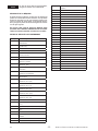
5HSODFLQJWKH¿OWHU
7KH¿OWHUPXVWEHUHSODFHGHYHU\RSHUDWLQJKRXUV
Follow the instructions shown in Fig. 6:
• Remove the rear bin
• Open the handles (pos. 1)
• Turn the catches (pos. 2) 180°
• 5HSODFHWKH¿OWHUSRV
• 7KHDUURZSRVPXVWEHSRLQWLQJLQWKHGLUHFWLRQRIDLUÀRZ
from the outside to the inside of the machine.
:$51,1*LQVHUWWKH¿OWHULQWKHGLUHFWLRQVKRZQSRV)LJ
:KHQ UHSODFLQJ WKH ¿OWHU PDNH VXUH WKHUH LV SHUIHFW WLJKWQHVV
EHWZHHQWKH¿OWHUDQGWKHJDVNHWV
PLEASE CAREFULLY FOLLOW THE REGULATIONS IN FORCE
FOR WASTE DISPOSAL.
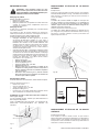
REPLACING AND ADJUSTING THE SIDE BRUSH
Replacement
After lifting the front of the machine, to replace the side brush,
XQVFUHZ WKH VFUHZ )LJ WKDW ¿[HV WKH EUXVK DQG UHPRYH WKH
brush. Replace it with the new brush and then tighten the screw,
complete with washer.
Adjustment
The height of the side brush is factory-adjusted for hard surfaces
(ceramic tile or natural stone). If the machine is going to operate
RQ D VRIW VXUIDFH ¿WWHG FDUSHW DGMXVW WKH EUXVK EHIRUH XVLQJ
LW IRU WKH ¿UVW WLPH UHIHUULQJ WR WKH LQGLFDWLRQV RQ WKH ODEHO DQG
proceeding as follows.
Turn the front cowling and remove the front bin.
The side brush is adjusted by loosening the screws pos. 1 Fig. 6/A
and manually positioning the brush at the desired height along the
slots. Once having determined the correct height, tighten the two
screws.
REPLACING AND ADJUSTING THE CENTRE BRUSH
Replacement (Fig.6/B)
To replace the centre brush, turn the front cowling and remove
WKHIURQWELQIURPWKHPDFKLQHXQVFUHZWKHIRXU¿[LQJVFUHZVDQG
remove the brush. When reassembling the new brush, make sure
the brush is placed in the right direction so as to move the dirt
towards the centre of the machine.
Fig. 6
Fig. 6/A
1
1
3
24
Hard
Floor Soft Floor
- 9 -

EN TRANSLATION OF ORIGINAL INSTRUCTIONS
Adjusting the centre brush.
7KHFHQWHUEUXVKKHLJKWLVIDFWRU\DGMXVWHGIRUKDUGÀRRUVHWWLQJ
)LJ',IXVLQJWKHPDFKLQHRQVRIWÀRRU&DUSHWORRVHQWKH
locking nut pos. 1 Fig. 6/D and turn the adjustment knob pos.
2 Fig. 6/D two full turns clockwise to decrease brush pressure.
Retighten locking nut.
For proper brush adjustment, the bristles should slightly bend
DJDLQVW WKH ÀRRU VXUIDFH $V WKH EUXVK ZHDUV LW¶V LPSRUWDQW WR
increase the brush pressure to maintain optimum sweeping
performance.
Too much brush pressure may prematurely wear
brush and decrease battery run time. When replac-
ing a worn brush, it’s important to readjust the set-
ting back to “0”.
REPLACING AND ADJUSTING THE BELT
To prepare the machine for replacement of one or more belts,
proceed as follows:
• turn the front cowling, remove the top cowling and the front
bin.
• DIWHUKDYLQJWDNHQRႇWKHOHIWZKHHOXQVFUHZWKHVFUHZVWKDW
¿[WKHEXPSHUDQGWKHULJKWVLGHFRYHUDQGUHPRYHWKHP
Replacing the side brush belt
• Remove the belt pos. 7 Fig. 7 from the pulley pos. 6 Fig. 7.
• 8QVFUHZWKH¿[LQJSLQSRV)LJDQGUHOHDVHWKHKRRNVRQ
the side arm pos. 9 Fig. 7 from the idle toothed ring.
• Remove the belt pos. 7 from the side arm pos. 9 Fig. 7.
• Replace the belt.
• Reattach the side arm pos. 9 Fig. 7 to the idle toothed ring.
• Retighten the pin pos. 8 Fig. 7.
• Reposition the belt pos. 7 Fig. 7 on the pulley pos. 6 Fig. 7.
Replacing the drive belt
• Remove the belt pos. 1 Fig. 7.
REPLACING THE FLAPS
2XWHUVLGHÀDSV
7RUHSODFHWKHVLGHÀDSVSRV)LJWDNHRႇWKHEDFNZKHHOV
8QVFUHZWKHVFUHZV¿[LQJWKHÀDSVWRWKHFKDVVLVSRV)LJ
DQGUHSODFHZLWKQHZÀDSV
,QQHUVLGHÀDSV
7RUHSODFHWKHLQQHUVLGHÀDSVSRV)LJOLIWWKHIURQWRIWKH
PDFKLQHDQGXQVFUHZWKHVFUHZVSRV)LJWKDW¿[WKHÀDSV
WRWKHFKDVVLV5HSODFHZLWKQHZÀDSV
&HQWUHÀDS
• 7DNHRႇWKHEDFNZKHHOVDQGWKHFRUUHVSRQGLQJVLGHFRYHUV
• Remove the drive pulley.
• Remove the rear bin.
• 8QVFUHZWKHWZRÀDS¿[LQJSLQVSRV)LJRQWKHVLGHV
of the chassis.
• +ROGWKHÀDSSRV)LJDQGSXOOLWWRZDUGVWKHRXWVLGHRI
the machine.
Reassembly:
• ,QVHUWWKHÀDSLQWKHVDPHGLUHFWLRQDVLWZDVUHPRYHG
• Insert the two references in the corresponding holes.
• 7LJKWHQWKH¿[LQJSLQVDQGUHDVVHPEOHWKHPDFKLQH
NOTE
ETET16859
2
1
Fig. 6/D
Fig. 7
Fig. 6/B
- 10 -

EN TRANSLATION OF ORIGINAL INSTRUCTIONS
REPLACING AND ADJUSTING THE CABLES
Replacing the drive cable
To replace the drive cable, proceed as follows:
•Remove the top cowling from the machine.
•Loosen the dowel on the cable locking pin.
• Pull the cable out of the locking pin and completely out of the
drive handle.
To reassemble the cable:
• Insert one end of the cable into the adjustment screw on the
drive handle (the end without the spherical cable lock).
•Insert the cable into the sheath.
•Attach the spherical cable lock to the handle.
•5XQWKHFDEOH¿UVWWKURXJKWKHUHJLVWHUDWWDFKHGWRWKHFKDVVLV
and then through the cable locking pin.
•Tighten the locking dowel.
To adjust the cable, use the two registers until obtaining the
desired position.
Replacing the side brush lifting cable
To replace the side brush lifting cable, proceed as follows:
•Remove the top cowling from the machine and the front bin.
•Remove the front bumper, the right-side wheel and the right-
side cover.
•Loosen the cable clamp.
•/RRVHQWKHGRZHORQWKH¿[LQJSLQ
• Remove the handle from the support and open it.
•Remove the cable from the two sheaths.
To reassemble the cable:
•Place the cable in the handle.
•&ORVHWKHKDQGOHDQG¿[LWWRLWVVXSSRUW
•Insert the cables into the sheaths.
• Lock one end of the cable with the clamp and the other end
ZLWKWKH¿[LQJSLQ
To adjust the cable, use the two registers until obtaining the
desired position.
TROUBLESHOOTING TABLE
FAULT CAUSE SOLUTION
The centre brush
GRHVQ¶WWXUQ
Belt broken Replace
Gear motor
damaged Contact service
centre
Wire detached Contact service
centre
Breaker tripped Reset
The side brushes
do not rotate. Belt broken Replace
7KHEDWWHU\GRHVQ¶W
hold its charge
No liquid (for lead-
acid battery) Top up
Loose terminal Tighten.
Dust comes out
of fan
%URNHQ¿OWHU Replace
Filter positioned
incorrectly Reposition
Worn gaskets Replace
The brushes wear
out too quickly Brushes pressed
too hard Adjust
Dust released
when working
:RUQÀDSV Replace
Filter clogged Clean
The suction motor
LVQ¶WZRUNLQJ
Motor burned out Contact service
centre
Wire detached Contact service
centre
Breaker tripped Reset
The machine
GRHVQ¶WVWDUW
Battery terminals
detached Check
Batteries
discharged Recharge
Machine not
moving Breaker tripped Reset
CIRCUIT BREAKERS
The machine is equipped with circuit breaker type fuses. These are
resettable devices designed to protect the electrical circuits of the
PDFKLQHDJDLQVWWKHUPDORYHUORDGE\VKXWWLQJRႇWKHÀRZRIFXUUHQW
Once a circuit breaker has been tripped, allow time for the circuit to
cool down, then reset the breaker switch manually by pressing the
relative button.
,IWKHRYHUORDGFRQGLWLRQWKDWWULSSHGWKHEUHDNHULVVWLOODႇHFWLQJWKH
FLUFXLWWKHIXVHZLOOFRQWLQXHWRVKXWRႇWKHÀRZRIFXUUHQWXQWLOWKH
problem has been located and remedied. To access the fuses, tilt the
front hood forward and remove the top section.
Fig. 8
- 11 -
NOTE: Earlier models are equipped with replaceable fuses.

EN TRANSLATION OF ORIGINAL INSTRUCTIONS
RECOMMENDED SPARE PARTS LIST
Part No. WEAR PARTS
PMVR00248 BRUSH KIT, SWEEPER, SIDE, STANDARD
SPPV00051 BRUSH KIT, SWEEPER, MAIN [COMPLETE]
FTDP76065 FILTER, PAPER, MAIN
FTDP00004 FILTER KIT, DUST, PRE-FILTER
MPVR76042 SKIRT KIT, FLAPS (includes *)
MPVR75928 *SKIRT, FLAP, LEFT, BLACK
MPVR75922 *SKIRT, FLAP, RIGHT, BLACK
MPVR75927 *SKIRT, FLAP, INNER, GRAY
MPVR85933 *SKIRT, FLAP, BACKSIDE
MPVR87400 SKIRT, FLAP, MAIN FRONT
MPVR00731 SKIRT, FLAP, FRONT
1069835 CORD, POWER, CHARGER, 120V [NA]
989584 CORD, POWER, CHARGER, 100V [JP]
1044068 CORD, POWER, CHARGER, 230V [EU]
1026325 CORD, POWER, CHARGER, 240V [AUS]
1044069 CORD, POWER, CHARGER, 230V [UK]
Part No. SERVICE PARTS
1053408 BATTERY, AGM, 12VDC, 140AH/C20 [NA/
EXP/JP]
994201 BATTERY, GEL, 12VDC, 105AH/C5 [EU/JP]
BACA00278 CHARGER, BATTERY, CBHD1 12V 10A [S7]
RDGR75782 MOTOR, ELE, GEAR
MOCC75780 MOTOR, ELE, FAN, 12VDC, 77MMD
MPVR87013 CARBON BRUSH, BRUSH MOTOR
1017696 KEY SET, REPLACEMENT
MPVR75836 BUSHING, LEVER [BELT TIGHTNER]
LAFN75834 BUSHING, ROCKER
RTRT24661 CASTER, SWIVEL, 100MMD, BLACK
CUVR75814 BEARING, NEEDLE [HK 1012]
SFVR00002 BEARING, BALL, 0.34B
LAFN75826 RING, BRUSH, SIDE [TOOTHED]
LAFN75833 BUSHING, BEARING
LAFN75838 BUSHING, HEX
RTRT75989 WHEEL, 250D 55W BLACK
PMTR00008 WHEEL ASSY, RIGHT WITH BEARING [ S7]
PMTR00010 WHEEL ASSY, LEFT, WITH BEARING [S7]
CUVR75815 VR, BEARING, FLANGE [S7]
CUVR86373 BEARING, BALL [6000 2RS]
VEVR26677 IMPELLER, FAN, 200MMD
MECE75944 CIRCUITBOARD, MAIN
LAFN00188 BUSHING
MPVR00017 SIDE BRUSH LEVER
MOCC00500 MOTOR KIT, SHAKER [S7]
MTCG13166 BELT, DRIVE
MTCG85335 BELT, SIDE BRUSH, BLUE
KTRI75926 GASKET KIT, FILTER [4 PC]
KTRI86322 GASKET KIT, FRONT CONTAINER [3 PC]
GUGO00285 GASKET, REAR CONTAINER
CUVR71988 BEARING, BELT TENSIONER
CUVR00005 BEARING, BRUSH, MAIN
CUVR86893 BEARING, SIDE BRUSH
CUVR37344 BEARING, NEEDLE, WHEEL
CUVR37341 BEARING, NEEDLE, WHEEL
In the event of other malfunctions, contact the
dealer
NOTES
SCRAPPING THE MACHINE
If the machine is to be scrapped, please note that the batter-
ies CANNOT be considered ordinary waste, rather they must
be disposed of in accordance with the laws in force. As the
PDFKLQHLVDQDVVHPEO\RIVHYHUDOGLႇHUHQWSDUWVLWLVUHFRP-
mended to disassemble it and sort the parts into groups of
the same material, in accordance with the laws in force.
DO NOT USE ANY PART BEING SCRAPPED AS A SPARE
PART. IN THIS CASE TOO, KEEP ALL PARTS OUT OF THE
REACH OF CHILDREN.
- 12 -

ES TRADUCCIÓN DE LAS INSTRUCCIONES ORIGINALES
DATOS Y CARACTERÍSTICAS TÉCNICAS ...........................................................................................................2
ADVERTENCIAS .....................................................................................................................................................3
MEDIDAS DE SEGURIDAD ....................................................................................................................................3
ETIQUETAS DE SEGURIDAD .................................................................................................................................4
POSICIÓN DE LA PLACA DE CARACTERÍSTICAS ..............................................................................................5
INTRODUCCIÓN ......................................................................................................................................................5
DESEMBALAJE ......................................................................................................................................................5
PREPARACIÓN DE LA MÁQUINA .........................................................................................................................5
Montaje del cepillo lateral ............................................................................................................................5
Montaje del manillar .....................................................................................................................................5
Preparación, instalación y sustitución de la batería .................................................................................6
MANDOS DE REGULACIONES ..............................................................................................................................6
PUESTA EN MARCHA ............................................................................................................................................6
OPERACIONES PARA UN FUNCIONAMIENTO CORRECTO ..............................................................................7
EXTRACCIÓN DEL CAJÓN RECOLECTOR DE RESIDUOS ................................................................................7
&DMyQGHODQWHUR¿J .................................................................................................................................7
&DMyQWUDVHUR¿J .....................................................................................................................................7
MANTENIMIENTO ORDINARIO ..............................................................................................................................7
MANTENIMIENTO DE LA BATERÍA .......................................................................................................................8
5HFDUJDGHODEDWHUtD ....................................................................................................................................8
CONFIGURACIONES DEL CARGADOR DE BATERÍA .........................................................................................8
DESPERFECTOS DEL CARGADOR DE BATERÍA ...............................................................................................8
MANTENIMIENTO DEL FILTRO .............................................................................................................................9
/LPSLH]DGHOSUH¿OWUR ....................................................................................................................................9
/LPSLH]DGHO¿OWUR .........................................................................................................................................9
6XVWLWXFLyQGHO¿OWUR .....................................................................................................................................9
SUSTITUCIÓN Y REGULACIÓN DEL CEPILLO LATERAL ..................................................................................9
SUSTITUCIÓN Y REGULACIÓN DEL CEPILLO CENTRAL ..................................................................................9
SUSTITUCIÓN Y REGULACIÓN DE LAS CORREAS ...........................................................................................10
Sustitución de la correa del cepillo lateral .................................................................................................10
Sustitución de la correa de tracción ...........................................................................................................10
SUSTITUCIÓN DE LOS FLAPS ..............................................................................................................................10
Flaps laterales externos ...............................................................................................................................10
Flaps laterales internos ................................................................................................................................10
Flap central ....................................................................................................................................................10
SUSTITUCIÓN Y REGULACIÓN DE LOS CABLES ..............................................................................................11
Sustitución del cable de tracción ................................................................................................................11
Sustitución del cable de levantamiento del cepillo lateral .......................................................................11
FUSIBLES ................................................................................................................................................................11
TABLA DE FALLOS-CAUSAS-SOLUCIONES .......................................................................................................11
DESGUACE DE LA MÁQUINA ...............................................................................................................................12
PIEZAS DE REPUESTO RECOMENDADAS ..........................................................................................................12
ÍNDICE
Copyright © 2019 Tennant Company. Todos los derechos reservados.
Tennant Company
10400 Clean Street
Eden Prairie, MN 55344-2650
Phone: (800) 553- 8033
www.tennantco.com
- 1 -

ES TRADUCCIÓN DE LAS INSTRUCCIONES ORIGINALES
DATOS Y CARACTERÍSTICAS TÉCNICAS
DESCRIPCIÓN
Anchura máxima mm 740
pulgadas 29
Longitud máxima mm 1245
pulgadas 49
Altura máxima con manillar mm 960
pulgadas 37.75
Anchura de limpieza con cepillo central mm 500
pulgadas 19.68
Anchura de limpieza con cepillo central y cepillo lateral mm 700
pulgadas 28
Peso con batería kg 121
lbs 266.76
Capacidad cajón de residuos delantero L45
ft31.6
Autonomía de trabajo h<3
6XSHU¿FLH¿OWUDQWH m² 1,03
ft211.08
Filtración H¿FD]DOSDUDSDUWtFXODVKDVWD
5 micras
Productividad (por hora) Valor Teórico Máx m2/h 2601
ft2/h 28000
Productividad (por hora) Área estimada m2/h 2508
ft2/h 27000
Potencia instalada / Absorción 710W / 59A
Tipo de baterías (sin mantenimiento) 12V 140Ah (C20)
Presión acústica, LpA 70 dBA
Incertidumbre de las medidas, kpA 3.0 dBA
Potencia acústica, LwA,g 80 dB
Vibraciones mano, ahv 1.1 m/seg2
Incertidumbre de las medidas, k 0.5 m/seg2
- 2 -

ES TRADUCCIÓN DE LAS INSTRUCCIONES ORIGINALES
ADVERTENCIAS
Esta máquina está diseñada solo para uso comercial. Su función
HVEDUUHUODVXFLHGDGORVUHVLGXRVVHFRV\HOSROYRGHVXSHU¿FLHV
secas, pavimentadas o alfombradas.
1R GHEH XWLOL]DUVH SDUD RWURV ¿QHV 1R XWLOLFH OD PiTXLQD SDUD
aspirar líquidos, materiales peligrosos o tóxicos.
Los operadores deben leer, conocer y respetar las siguientes
advertencias.
En este manual, el símbolo de advertencia que se muestra a
continuación y la frase «ADVERTENCIA DE SEGURIDAD» se
XWLOL]DQFRQORVVLJXLHQWHVVLJQL¿FDGRV
$7(1&,Ï1DGYLHUWHVREUHSHOLJURVRSURFHGLPLHQ-
WRVSHOLJURVRVTXHSRGUtDQFDXVDUOHVLRQHVJUDYHV
o la muerte de personas.
ADVERTENCIA DE SEGURIDAD: indica los procedimientos
TXHVH GHEHQ VHJXLU SDUDXWLOL]DU OD PiTXLQD UHVSHWDQGROD
VHJXULGDG
El incumplimiento de dichas advertencias puede
causar lesiones, electrocución, descargas eléctricas, incendios
o explosiones.
$7(1&,Ï1QRDFFLRQHODPiTXLQDHQSUHVHQFLDGH
OtTXLGRVRYDSRUHVLQÀDPDEOHVRSROYRVFRPEXV-
tibles.
La máquina no está equipada con motores a prueba de explosión.
La chispa generada en los motores eléctricos durante el encendido
y durante el funcionamiento podría causar un incendio o una
explosión si la máquina se utilizara en presencia de líquidos/
YDSRUHVLQÀDPDEOHVRSROYRVFRPEXVWLEOHV
$7(1&,Ï1 QR DVSLUH PDWHULDOHV Wy[LFRV QL LQÀD-
mables, residuos ardientes o humeantes.
$7(1&,Ï1ODVEDWHUtDVHPLWHQKLGUyJHQR
0DQWpQJDVHOHMRVGHFKLVSDV\OODPDVDELHUWDV
Deje abierto el alojamiento de la batería mientras
VHFDUJD
$7(1&,Ï1 QR FDUJXH ODV EDWHUtDV VL HO FDEOH GH
DOLPHQWDFLyQGHOFDUJDGRUGHEDWHUtDHVWXYLHUDGD-
xDGR1RPRGL¿TXHODFODYLMD
Si el cable de alimentación del cargador de batería estuviera
dañado o roto, hágalo sustituir por el fabricante, un centro de
DVLVWHQFLDDXWRUL]DGRRXQWpFQLFRFDOL¿FDGR
$7(1&,Ï1DQWHVGHUHDOL]DUFXDOTXLHUWLSRGHRSH-
ración, desconecte los cables de la batería y el ca-
EOHGHDOLPHQWDFLyQGHOFDUJDGRUGHEDWHUtD
$'9(57(1&,$'(6(*85,'$'QRXWLOLFHODPiTXLQDHQVX-
SHU¿FLHVPRMDGDV1RH[SRQJDODPiTXLQDDODOOXYLD
/DPiTXLQDGHEHJXDUGDUVH~QLFDPHQWHHQOXJDUHVFHUUDGRV
La siguiente información indica condiciones potencialmente
peligrosas para el operador o el aparato.
MEDIDAS DE SEGURIDAD
No utilice la máquina:
• (QSUHVHQFLDGHVXVWDQFLDVLQÀDPDEOHVRH[SORVLYDV
• Si no está capacitado ni autorizado para hacerlo.
• Si no ha leído minuciosamente el manual de uso.
• Si la máquina no está en perfectas condiciones.
• 6LQRHVWXYLHUDPRQWDGRHOFDMyQ\RORV¿OWURV
Cargador de baterías:
• Asegúrese de que la toma de corriente para alimentar
el cargador de baterías esté conectada a una red de
tierra adecuada y que esté protegida por un interruptor
magnetotérmico y diferencial.
• Asegúrese de que las características eléctricas del cargador
de baterías (tensión, frecuencia, potencia absorbida),
indicadas en la placa de características, respondan a las del
sistema de distribución de la energía eléctrica.
Antes de encender la máquina:
• Compruebe que los dispositivos de seguridad estén montados
y funcionen correctamente.
Cuando la máquina está funcionando:
• No aspire residuos ardientes o humeantes, tales como
cigarrillos, cerillas o brasas.
• No utilice la máquina para aspirar líquidos.
• Comunique inmediatamente posibles daños o fallos.
• 3URFHGD OHQWDPHQWH VREUH ODV VXSHU¿FLHV HQ SHQGLHQWH \
resbaladizas.
• 1R GHMH OD PiTXLQD VLQ YLJLODQFLD R HQ VXSHU¿FLHV HQ
pendiente.
• 1RXWLOLFHODPiTXLQDSDUDUHFRJHUFDEOHVFXHUGDVÀHMHVR
materiales similares.
• Asegúrese de que el área de trabajo esté iluminada.
• Mantenga la máquina fuera del alcance de los niños.
• No transporte personas ni cosas.
• En entornos polvorientos, utilice gafas y guantes protectores.
Antes de alejarse de la máquina o antes de realizar trabajos de
mantenimiento:
• 'HWHQJDODPiTXLQDVREUHXQDVXSHU¿FLHHQSODQR
• Apague la máquina.
Durante las operaciones de mantenimiento y reparación:
• Manténgase lejos de las piezas móviles. No use chaquetas,
camisas ni ropa con mangas que puedan engancharse.
• Antes de trabajar en la máquina, desconecte la batería y la
clavija del cargador de batería.
• Utilice piezas de repuesto originales o aprobadas.
• Las reparaciones deben ser realizadas por un técnico
FDOL¿FDGR
• 1RPRGL¿TXHODPiTXLQDSRUQLQJ~QPRWLYR
• Para manipular la batería o los cables de la batería, póngase
guantes y gafas protectoras.
• Evite el contacto con el ácido de la batería.
• 1RDFFLRQHODPiTXLQDHQSHQGLHQWHVPD\RUHVDO
Durante el transporte de la máquina:
• Apague la máquina.
• Solicite ayuda para el levantamiento.
• Para cargar/descargar en/desde un camión o remolque,
utilice una rampa adecuada.
• )LMHODPiTXLQDDOFDPLyQRUHPROTXHFRQFRUUHDVHVSHFt¿FDV
- 3 -

ES TRADUCCIÓN DE LAS INSTRUCCIONES ORIGINALES
ETIQUETAS DE SEGURIDAD
La máquina tiene aplicadas etiquetas de seguridad. Si estuvieran dañadas, sustitúyalas.
ATENCIÓN, PELIGRO ÓRGANOS MÓVILES
ATENCIÓN, PELIGRO PRESENCIA DE ÁCIDOS
ATENCIÓN, SUPERFICIE CALIENTE
PENDIENTE SUPERABLE
MANUAL DEL OPERADOR, INSTRUCCIONES DE FUNCIONAMIENTO
LEER EL MANUAL DEL OPERADOR
SÍMBOLO DE CORRIENTE CONTINUA
APARATO DE CLASE III. UN APARATO SE DEFINE DE CLASE III CUANDO LA
PROTECCIÓN CONTRA LA ELECTROCUCIÓN SE BASA EN EL HECHO DE
QUE NO HAY TENSIONES SUPERIORES A LA TENSIÓN DE SEGURIDAD
MUY BAJA SELV (SAFETY EXTRA-LOW VOLTAGE). ESTE APARATO ESTÁ
ALIMENTADO POR UNA BATERÍA O POR UN TRANSFORMADOR SELV.
RESIDUO ESPECIAL, NO DESECHAR EN LOS RESIDUOS COMUNES.
ETIQUETA DE SEGURIDAD. LA ETIQUETA DE SEGURIDAD APARECE EN LA
MÁQUINA EN LA POSICIÓN INDICADA. SUSTITUYA LA ETIQUETA SI FALTARA
O SI ESTUVIERA DAÑADA O FUERA ILEGIBLE.
ATENCIÓN, PELIGRO DE ABRASIÓN O ENREDO TOCANDO EL CEPILLO
MIENTRAS GIRA
- 4 -

ES TRADUCCIÓN DE LAS INSTRUCCIONES ORIGINALES
POSICIÓN DE LA PLACA DE CARACTERÍSTICAS
Asegúrese de que la máquina esté equipada con la placa que
indica el número de serie colocada como se muestra en la Fig. 1
(para acceder a la placa, retire el capó superior).
PREPARACIÓN DE LA MÁQUINA
Montaje del cepillo lateral
• Coloque la palanca de elevación del cepillo (pos. 1 Fig. 3) en
la posición «0».
• Desenrosque el tornillo del eje del cepillo lateral.
• Coloque el cepillo en el eje (Fig. 2).
• Enrosque el tornillo con su arandela.
INTRODUCCIÓN
(VWH PDQXDO GH LQVWUXFFLRQHV WLHQH OD ¿QDOLGDG GH VHUYLU FRPR
guía y contiene la información práctica para la seguridad,
funcionamiento, ajuste y mantenimiento de la máquina. La
máquina ha sido diseñada y fabricada para asegurar el máximo
de las prestaciones, comodidad y facilidad de trabajo en una
amplia variedad de condiciones.
Antes de la entrega, la máquina ha sido controlada en fábrica
y por nuestro concesionario para garantizar que se entregue
en perfectas condiciones. Para mantener la máquina en dichas
condiciones o asegurar un trabajo sin problemas, es indispensable
que se lleven a cabo las operaciones de mantenimiento indicadas
en este manual.
DESEMBALAJE
Desembale la máquina con mucho cuidado evitando realizar
maniobras que puedan dañarla; una vez desembalada,
compruebe la integridad de todas sus partes. De lo contrario, NO
utilice la máquina y póngase en contacto con su distribuidor. Por
razones de embalaje y transporte, algunas piezas y opcionales
pueden suministrarse sueltos; para el montaje correcto, siga las
instrucciones dadas en los capítulos respectivos de este manual.
Contenido del embalaje:
1 Máquina
1 Cepillo lateral
1 Manual de instrucciones
1 Garantía
1 Kit de herramientas
2 Llaves de encendido
1 Batería
Si faltara alguno de los elementos antes mencionados, póngase
en contacto de inmediato con el distribuidor.
Asegúrese de que el material de embalaje (bolsas, cartones,
palets, ganchos, etc.) sea colocado en una zona adecuada fuera
del alcance de los niños.
Las llaves de encendido se colocan dentro
GHOVREUHGHORVGRFXPHQWRVSDUDTXHQR
se pierdan durante el transporte.
Montaje del manillar
• 5HWLUHHOFDSyVXSHULRUSDUDDFFHGHUDORVWRUQLOORVGH¿MDFLyQ
del manillar.
• Levante el manillar hasta la posición de uso (pos. 1 Fig. 2/A).
• $SULHWHORVWRUQLOORVGH¿MDFLyQGHOPDQLOODUSRV)LJ$
(utilice la llave suministrada con la máquina).
NOTAS
FIG. 1
Fig. 2
Fig. 2/A
12
- 5 -

ES TRADUCCIÓN DE LAS INSTRUCCIONES ORIGINALES
Preparación, instalación y sustitución de la batería
PARA SU SEGURIDAD: póngase guantes protectores y una
protección para los ojos cuando deba manipular la batería y los
cables de la batería. Evite el contacto con el ácido de la batería.
Póngase en contacto con Tennant o el distribuidor para obtener
recomendaciones sobre la sustitución de la batería.
Dimensiones máx. de la batería: 18 cm (7,00 in) A x 32 cm (12,50
in) L x 24 cm (9,38 in) H
IMPORTANTE: es NECESARIO establecer nuevamente las
FRQ¿JXUDFLRQHV GHO FDUJDGRU GH EDWHUtD D ERUGR FXDQGR VH
cambia a un tipo diferente de batería, es decir, CON LÍQUIDO (de
plomo) o HERMÉTICA (de gel). Véase CONFIGURACIONES DEL
CARGADOR DE BATERÍA
(O FDUJDGRU GH EDWHUtD HVWi FRQ¿JXUDGR GH IiEULFD SDUD ODV
baterías de Gel/AGM.
Instalación de la Batería:
• Retire la llave de la máquina.
• Gire el capó delantero y retire el capó superior para acceder
al alojamiento de la batería.
• Coloque con cuidado la batería en el contenedor con el borne
de la batería dirigido hacia la parte trasera de la máquina
y conecte los cables a la batería: el cable ROJO al polo
POSITIVO (+), el cable NEGRO al NEGATIVO (-) (Fig. 2/B).
• Sujete la batería con la correa.
• Cargue la batería. Véase RECARGA DE LA BATERÍA
MANDOS DE REGULACIONES
1) Palanca de mando del cepillo lateral: colocando la palanca en
la posición «I», el cepillo lateral se coloca en la posición de trabajo
y comienza a girar. Para detener el cepillo, vuelva a colocar la
palanca en la posición «0».
2) Interruptor de llave: alimentación de la máquina.
3) Indicador luminoso de estado de carga: muestra la carga de la
batería durante el funcionamiento de la máquina.
4) Palanca de tracción: tirando de esta palanca, el movimiento se
transmite a la máquina que comienza a avanzar.
3DODQFDGHODO]DÀDSDOWLUDUGHHVWDSDODQFDHOFHSLOORFHQWUDO
puede barrer objetos voluminosos.
%RWyQVDFXGLGRUGH¿OWURHOpFWULFR
7) Interruptor de la aspiración.
PUESTA EN MARCHA
$'9(57(1&,$'(6(*85,'$'/DPiTXLQDGHEHVHUXWLOL]D-
da solo por personal capacitado y autorizado.
1RDVSLUHOtTXLGRVQLGHMHODPiTXLQDVLQYLJLODQFLD5HWLUHOD
OODYHDQWHVGHDEDQGRQDUODPiTXLQD\PDQWpQJDODIXHUDGHO
alcance de los niños.
$'9(57(1&,$'(6(*85,'$'QRXWLOLFHODPiTXLQDHQVX-
SHU¿FLHVPRMDGDV
Para la puesta en marcha de la máquina, proceda de la siguiente
manera:
• Compruebe que el cepillo lateral pos. 1 Fig. 3 esté en la
posición «0».
• Coloque el interruptor de llave pos. 2 Fig. 3 en la posición «I».
• Después de haber girado la llave, espere alrededor de 10 s
antes de poner en marcha la máquina. Controle a través del
indicador pos. 3 Fig. 3 que la batería esté completamente
cargada antes de comenzar a trabajar, de lo contrario cargue
la batería.
• Active el aspirador colocando el interruptor pos. 7 Fig. 3 en
la posición «I».
&XDQGRXWLOLFHODPiTXLQDSDUDVXGHVSOD]DPLHQWR
DSDJXHHODVSLUDGRUFRORFDQGRHOLQWHUUXSWRUSRV
)LJHQODSRVLFLyQ©ª
• Tire de la palanca de tracción pos. 4 Fig. 3 y proceda con la
limpieza. Si fuera necesario, accione la palanca pos. 1 Fig. 3
colocándola en la posición «I» para activar el cepillo lateral. Al
¿QDOGHOWUDEDMRVLKXELHUDXWLOL]DGRHOFHSLOORODWHUDOFRORTXH
la palanca correspondiente en la posición «0», apague la
máquina y retire las llaves del cuadro de mandos.
Un dispositivo automático evita trabajar más allá de un determinado
umbral de descarga de la batería.
Una vez que se alcanza dicho límite, la máquina se detiene y debe
recargarse para reanudar el trabajo.
NOTAS
Fig. 2/B
1
5
26-7
3
4
Fig. 3
- 6 -

ES TRADUCCIÓN DE LAS INSTRUCCIONES ORIGINALES
OPERACIONES PARA UN FUNCIONAMIENTO
CORRECTO
Después de realizar las operaciones de puesta en marcha
inicial y arranque de la máquina, se puede comenzar a trabajar
con la barredora. Para obtener siempre el máximo rendimiento
de la barredora, se recomienda seguir algunas indicaciones
que mantendrán la máquina siempre en los niveles más altos y
minimizarán el riesgo de daños a la máquina.
Es importante:
• 1REDUUHUFDEOHVFXHUGDVÀHMHVQLRWURVPDWHULDOHVVLPLODUHV
• En presencia de objetos voluminosos y muy ligeros
(papel, hojas, etc.), levantar la parte frontal de la máquina
presionando el manillar durante el tiempo necesario para
barrer los residuos.
• 8WLOLFHODSDODQFDDO]DÀDSSDUDUHFRJHUREMHWRVYROXPLQRVRV
• 6DFXGLUHO¿OWURDO¿QDOGHOWUDEDMRYpDVH0$17(1,0,(172
DEL FILTRO).
• Mantener regulado el cepillo central (véase REGULACIÓN
DEL CEPILLO CENTRAL).
EXTRACCIÓN DEL CAJÓN RECOLECTOR DE
RESIDUOS
ATENCIÓN: antes de retirar el cajón recolector de
UHVLGXRVDVHJ~UHVHGHTXHWRGDVODVIXQFLRQHVGH
ODPiTXLQDHVWpQDSDJDGDV(VWRHYLWDODSRVLELOL-
GDGGHWRFDUHOFHSLOORPLHQWUDVJLUD
ATENCIÓN: LA RECOGIDA DE LOS RESIDUOS DEBE REA-
LIZARSE RESPETANDO ESCRUPULOSAMENTE LAS LEYES
VIGENTES PARA TAL FIN.
&DMyQGHODQWHUR¿J
• Gire/abra el capó delantero.
• Levante y gire los 2 cierres del cajón.
• Sujete el cajón por la/s asa/s y retírelo tirando del mismo
hacia arriba.
• Vacíe el cajón.
Para montar de nuevo el cajón:
• Introduzca el cajón en la máquina.
• Gire y baje los 2 cierres.
• Gire/cierre el capó delantero.
&DMyQWUDVHUR¿J
• Levante y gire los 2 cierres del cajón trasero.
• Sujete el cajón trasero por el asa y retírelo de la máquina.
• Vacíe el cajón.
Para montar de nuevo el cajón:
• Introduzca el cajón en la máquina.
• Gire y presione los 2 cierres.
MANTENIMIENTO ORDINARIO
ADVERTENCIA DE SEGURIDAD: Las posibles reparaciones
deben ser realizadas por un técnico autorizado. Utilice piezas
GHUHSXHVWRRULJLQDOHVRDSUREDGDV
$7(1&,Ï1DQWHVGHUHDOL]DUFXDOTXLHUWLSRGHRSH-
UDFLyQHQODPiTXLQDGHVFRQHFWHORVFDEOHVGHOD
EDWHUtD\HOFDEOHGHDOLPHQWDFLyQGHOFDUJDGRUGH
batería.
ATENCIÓN: todos los trabajos de mantenimiento
GHEHQUHDOL]DUVHFRQODPiTXLQDDSDJDGD
CONTROLES
En el momento
de la entrega
Cada 10 horas
Cada 50 horas
Cada 100
horas
Cada 200
horas
Tensión de las correas X
Apriete de tuercas y tornillos X
Condiciones de los cepillos X
Controle la hermeticidad de las
juntas X
Controle si todas las funciones
están activas XXXX
6XVWLWXFLyQGHO¿OWUR X
Fig. 4
FIG. 5
Fig. 5/A
- 7 -
La page est en cours de chargement...
La page est en cours de chargement...
La page est en cours de chargement...
La page est en cours de chargement...
La page est en cours de chargement...
La page est en cours de chargement...
La page est en cours de chargement...
La page est en cours de chargement...
La page est en cours de chargement...
La page est en cours de chargement...
La page est en cours de chargement...
La page est en cours de chargement...
La page est en cours de chargement...
La page est en cours de chargement...
La page est en cours de chargement...
La page est en cours de chargement...
La page est en cours de chargement...
La page est en cours de chargement...
-
 1
1
-
 2
2
-
 3
3
-
 4
4
-
 5
5
-
 6
6
-
 7
7
-
 8
8
-
 9
9
-
 10
10
-
 11
11
-
 12
12
-
 13
13
-
 14
14
-
 15
15
-
 16
16
-
 17
17
-
 18
18
-
 19
19
-
 20
20
-
 21
21
-
 22
22
-
 23
23
-
 24
24
-
 25
25
-
 26
26
-
 27
27
-
 28
28
-
 29
29
-
 30
30
-
 31
31
-
 32
32
-
 33
33
-
 34
34
-
 35
35
-
 36
36
-
 37
37
-
 38
38


dans d''autres langues
Documents connexes
Autres documents
-
Tennant M-S680 Mode d'emploi
-
Saeco RI9829/11 Manuel utilisateur
-
Nilfisk-ALTO SCRUBTEC 343.2 Manuel utilisateur
-
Generic TR 125 Manuel utilisateur
-
York TIWM012B21S Manuel utilisateur
-
Philips RI9755/11 Le manuel du propriétaire
-
DAB DAB E.SYBOX Instruction For Installation And Maintenance
-
Zephyr ZGE-E30AS290 Manuel utilisateur
-
Zephyr ZML-M90BS Hood User Manual
-
 Ferve DUAL F-908 Manuel utilisateur
