WIKA IV10 tag:model:IV11 tag:model:IV20 tag:model:IV21 tag:model:IV30 tag:model:IV31 tag:model:IV50 tag:model:IV51 Mode d'emploi
- Catégorie
- Outils électroportatifs
- Taper
- Mode d'emploi

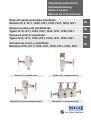
Model IV10, needle valve Model IV11, multiport valve
Model IV20, block-and-bleed valve Model IV51, 5-valve manifold
DE
EN
Operating instructions
Betriebsanleitung
Mode d‘emploi
Manual de instrucciones
ES
FR
Shut-o valves and valve manifolds
Models IV10, IV11, IV20, IV21, IV30, IV31, IV50, IV51
Absperrventile und Ventilblöcke
Typen IV10, IV11, IV20, IV21, IV30, IV31, IV50, IV51
Vannes d'arrêt et manifolds
Types IV10, IV11, IV20, IV21, IV30, IV31, IV50, IV51
Válvulas de cierre y manifolds
Modelos IV10, IV11, IV20, IV21, IV30, IV31, IV50, IV51

2
14294094.01 10/2019 EN/DE/FR/ES
Operating instructions shut-o valves and valve manifolds
DE
EN
ES
FR
Operating instructions
Shut-o valves and valve manifolds
Page 3 - 26
Betriebsanleitung
Absperrventile und Ventilblöcke
Seite 27 - 50
Mode d‘emploi
Vannes d'arrêt et manifolds
Page 51 - 75
Manual de instrucciones
Válvulas de cierre y manifolds
Página 76 - 98
© 10/2019 WIKA Alexander Wiegand SE & Co. KG
All rights reserved. / Alle Rechte vorbehalten.
WIKA
®
is a registered trademark in various countries.
WIKA
®
ist eine geschützte Marke in verschiedenen Ländern.
Prior to starting any work, read the operating instructions!
Keep for later use!
Vor Beginn aller Arbeiten Betriebsanleitung lesen!
Zum späteren Gebrauch aufbewahren!
Lire le mode d‘emploi avant de commencer toute opération !
A conserver pour une utilisation ultérieure !
¡Leer el manual de instrucciones antes de comenzar cualquier trabajo!
¡Guardar el manual para una eventual consulta!

EN
WIKA operating instructions, shut-o valves and valve manifolds
14294094.01 10/2019 EN/DE/FR/ES
3
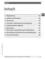
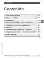
Contents
Contents
1. General information 4
2. Design and function 5
3. Safety 6
4. Transport, packaging and storage 11
5. Commissioning, operation 12
6. Faults 17
7. Maintenance, repair and cleaning 19
8. Dismounting, return and disposal 21
9. Specications 24

EN
14294094.01 10/2019 EN/DE/FR/ES
4 WIKA operating instructions, shut-o valves and valve manifolds
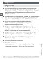
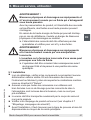
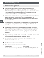
1. General information
■
The valves described in the operating instructions have been
designed and manufactured using state-of-the-art technology. All
components are subject to stringent quality and environmental
criteria during production. Our management systems are certied to
ISO 9001.
■
These operating instructions contain important information on
handling the product. Working safely requires that all safety
instructions and work instructions are observed.
■
Observe the relevant local accident prevention regulations and
general safety regulations for the product's range of use.
■
The operating instructions are part of the product and must be kept
in the immediate vicinity of the valve and readily accessible to skilled
personnel at any time. Pass the operating instructions on to the next
operator or owner of the product.
■
Skilled personnel must have carefully read and understood the
operating instructions prior to beginning any work.
■
The general terms and conditions contained in the sales
documentation shall apply.
■
Subject to technical modications.
■
Further information:
- Internet address: www.wika.de / www.wika.com
- Relevant data sheets: AC 09.19, AC 09.22, AC 09.23
1. General information

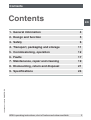
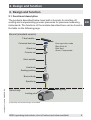
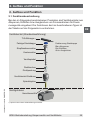
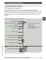
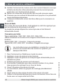
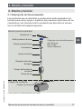
Bonnet (standard version)
Dust cap colour code
Blue: Shut o
Red: Vent
Green: Compensate
EN
WIKA operating instructions, shut-o valves and valve manifolds
14294094.01 10/2019 EN/DE/FR/ES
5
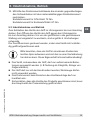
2. Design and function
2. Design and function
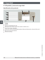
2.1 Functional description
The products described below have built-in bonnets for shutting o,
venting and compensating process pressures for pressure measuring
instruments. The functions of the models described here can be found in
the table on the following page.
T-bar handle
1)
Coloured dust cap
Gland nut
Counter nut
Valve spindle
Seal bush
Sealing packing
Bonnet body
Spindle tip
Locking pin
Sealing ring
Valve body
1) Optionally other handle designs are available

EN
14294094.01 10/2019 EN/DE/FR/ES
6 WIKA operating instructions, shut-o valves and valve manifolds
Model Number of bonnets
Shut o Vent
1)
Compensate
IV10 1 - -
IV11 1 - -
IV20, IV21 1 1 -
IV30, IV31 2 - 1
IV50, IV51 2 2 1
1) Venting with bonnet, for further venting options (e.g. via vent screw) see data sheet
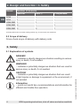
2.2 Scope of delivery
Cross-check scope of delivery with delivery note.
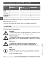
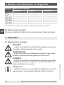
3. Safety
3.1 Explanation of symbols
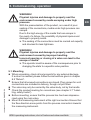
DANGER!
... indicates a directly dangerous situation resulting in serious
injury or death, if not avoided.
WARNING!
... indicates a potentially dangerous situation that can result in
serious injury or death, if not avoided.
CAUTION!
... indicates a potentially dangerous situation that can result
in light injuries or damage to equipment or the environment, if
not avoided.
Information
... points out useful tips, recommendations and information for
ecient and trouble-free operation.
2. Design and function / 3. Safety

EN
WIKA operating instructions, shut-o valves and valve manifolds
14294094.01 10/2019 EN/DE/FR/ES
7
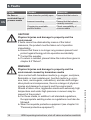
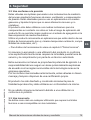
3.2 Intended use
These valves are used for the separation of measuring instruments from
the process by means of shut-o, venting and pressure compensating
function(s) They are designed for use in applications with clean gaseous
and liquid media that are not highly viscous or crystallising.
The product must only be used with media which are not harmful to
the wetted parts over the entire operating range of the instrument. Any
change in the state of the matter or any decomposition of unstable media
is not permitted.
Only use the product in applications that lie within its technical perfor-
mance limits (e.g. max. ambient temperature, material compatibility, ...).
→ For performance limits see chapter 9 “Specications”.
Improper handling or operation of the product outside of its technical
specifications requires the instrument to be taken out of service
immediately and inspected by an authorised service engineer.
These valves do not have their own potential ignition source. The
responsibility for the safe use in hazardous areas in accordance with
the accepted standards of technology rests with the operator.
For the reasons mentioned above, these valves are not marked and do
not have their own certification.
The product has been designed and built solely for the intended use
described here, and may only be used accordingly.
The manufacturer shall not be liable for claims of any type based on
operation contrary to the intended use.
3.3 Improper use
Improper use is dened as any application that exceeds the technical
performance limits or is not compatible with the materials.
3. Safety

EN
14294094.01 10/2019 EN/DE/FR/ES
8 WIKA operating instructions, shut-o valves and valve manifolds
WARNING!
Injuries through improper use
Improper use of the product can lead to hazardous situations
and injuries.
▶
Refrain from unauthorised modifications to the product.
▶
Do not use the product with abrasive or viscous media.
Any use beyond or dierent to the intended use is considered as
improper use.
3.4 Responsibility of the operator
The product is used in the industrial sector. The operator is therefore
responsible for legal obligations regarding safety at work.
The safety instructions within these operating instructions, as well as the
safety, accident prevention and environmental protection regulations for
the application area must be maintained.
The operator is obliged to maintain the product label in a legible condi-
tion.
To ensure safe working on the product, the operating company must
ensure the following:
■
The operating personnel are regularly instructed in all topics
regarding work safety, rst aid and environmental protection
and know the operating instructions and in particular, the safety
instructions contained therein.
■
The operating personnel have read the operating instructions and
taken note of the safety instructions contained therein.
■
The intended use for the application is complied with.
■
Following testing, improper use of the product is excluded.
3. Safety

EN
WIKA operating instructions, shut-o valves and valve manifolds
14294094.01 10/2019 EN/DE/FR/ES
9
3.5 Personnel qualication
WARNING!
Risk of injury should qualication be insucient
Improper handling can result in considerable injury and
damage to equipment.
▶
The activities described in these operating instructions
may only be carried out by skilled personnel who have the
qualications described below.
Skilled personnel
Skilled personnel, authorised by the operator, are understood to be
personnel who, based on their technical training, knowledge of measu-
rement and control technology and on their experience and knowledge
of country-specic regulations, current standards and directives, are
capable of carrying out the work described and independently recognis-
ing potential hazards.
Operating personnel
The personnel trained by the operator are understood to be personnel
who, based on their education, knowledge and experience, are capab-
le of carrying out the work described and independently recognising
potential hazards.
Special operating conditions require further appropriate knowledge, e.g.
of aggressive media.
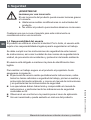
3.6 Personal protective equipment
The personal protective equipment is designed to protect the skilled
personnel from hazards that could impair their safety or health during
work. When carrying out the various tasks on and with the product, the
skilled personnel must wear personal protective equipment.
Follow the instructions displayed in the work area regarding
personal protective equipment!
The requisite personal protective equipment must be provided by the
operating company.
3. Safety

EN
14294094.01 10/2019 EN/DE/FR/ES
10 WIKA operating instructions, shut-o valves and valve manifolds
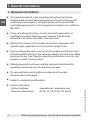
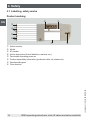
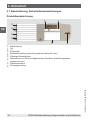
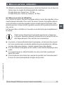
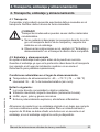
3.7 Labelling, safety marks
Product marking
Article number
Model
ID number
Article description (thread denition, material, etc.)
Permissible operating pressure
Product traceability information (production date, lot number etc.)
Functional diagram
Flow direction
3. Safety

EN
WIKA operating instructions, shut-o valves and valve manifolds
14294094.01 10/2019 EN/DE/FR/ES
11
4. Transport, packaging and storage
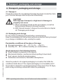
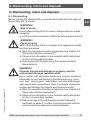
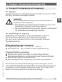
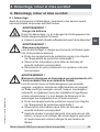
4.1 Transport
Check the product for any damage that may have been caused by trans-
port. Obvious damage must be reported immediately.
CAUTION!
With improper transport, a high level of damage to
property can occur.
▶
When unloading packed goods upon delivery as well as
during internal transport, proceed carefully.
▶
With internal transport, observe the instructions in chapter
4.2 “Packaging and storage”.
4.2 Packaging and storage
Do not remove packaging until just before commissioning.
Keep the packaging as it will provide optimum protection during transport
(e.g. change in installation site, sending for repair).
Permissible conditions at the place of storage:
■
Storage temperature: -60 ... +70 °C (-76 ... +158 °F)
■
Humidity: 35 ... 85 % relative humidity (no condensation)
Avoid exposure to the following factors:
■
Direct sunlight or proximity to hot objects
■
Mechanical vibration, mechanical shock (putting it down hard)
■
Soot, vapour, dust and corrosive gases
■
Hazardous environments, ammable atmospheres
Store the product in its original packaging in a location that fulls the
conditions listed above. If the original packaging is not available and if
the product is stored for a prolonged period of time (more than 30 days),
place a bag containing a desiccant inside the packaging.
4. Transport, packaging and storage

EN
14294094.01 10/2019 EN/DE/FR/ES
12 WIKA operating instructions, shut-o valves and valve manifolds
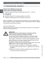
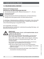
5. Commissioning, operation
Personnel: Skilled personnel
Tools and mounting material:
■
Torque spanner set, open-ended spanner set (17 ... 32 mm)
■
Allen key set
■
Screwdriver
■
Suitable lubricants for sealing elements and bolts
■
Suitable sealing material for threaded connections
Before installation, commissioning and operation, ensure that the appro-
priate product has been selected in terms of operating conditions, design
and specic measuring conditions.
Only use original parts.
Always observe the mounting and operating instructions of accessories
when commissioning them.
WARNING!
Physical injuries and damage to property and the
environment caused by hazardous media
Upon contact with hazardous media (e.g. with ammable
or toxic substances), harmful media (e.g. corrosive, toxic,
carcinogenic, radioactive), and also with refrigeration plants
and compressors, there is a danger of physical injuries and
damage to property and the environment.
Aggressive media with extremely high temperature and under
high pressure may be present at the product.
▶
For these media, in addition to all standard regulations,
the appropriate existing codes or regulations must also be
followed.
▶
Wear the requisite protective equipment (see chapter 3.6
“Personal protective equipment”).
5. Commissioning, operation

EN
WIKA operating instructions, shut-o valves and valve manifolds
14294094.01 10/2019 EN/DE/FR/ES
13
WARNING!
Physical injuries and damage to property and the
environment caused by media escaping under high
pressure
With the pressurisation of the product, as a result of poor
sealing of the connections, media under high pressure can
escape.
Due to the high energy of the media that can escape in
the event of a failure, the possibility of physical injuries and
damage to property exists.
▶
The sealing of the connections must be carried out expertly
and checked for leak tightness.
WARNING!
Physical injuries and damage to property and the
environment caused by improper handling.
Incorrect opening or closing of a valve can lead to the
escape of media.
▶
The operator must be aware of the consequences prior to
changing the state to a specic valve position.
5.1 Mounting
■
When unpacking, check all components for any external damage.
If a return is needed, please follow the instructions given in chapter
8.2 “Return”.
■
Ensure that all unused connections are closed. Plug screws for vent
connections are included in delivery, though not pre-tted.
■
The valve may only be carried by the valve body, not by the handle
■
Check the product marking for correctness (see chapter 3.7 “Label-
ling, safety marks”).
■
Before mounting, ensure that the process line has been depressu-
rised using the main valve.
■
Mount the measuring instrument at the right connection. Ensure that
the ow direction arrow points from the process connection towards
the measuring instrument.
5. Commissioning, operation

EN
14294094.01 10/2019 EN/DE/FR/ES
14 WIKA operating instructions, shut-o valves and valve manifolds
5. Commissioning, operation
■
Remove the protection caps of the required process connections.
■
Ensure that the sealing faces are clean and do not show any mecha-
nical damage.
■
The correct sealing element must be used for the respective
connection.
Threaded connection
To screw in threaded connections the appropriate tool must only be
applied through the spanner ats provided for this purpose.
The tightening torque is dependent on the process connection and
sealing element used.
Flange connection
Applicable models: IV20, IV21, IV30, IV31, IV50, IV51
Use only the bolts and sealing rings included in delivery:
Models IV20, IV21: 2 bolts, 1 sealing ring
Models IV30, IV31, IV50, IV51: 4 bolts, 2 sealing rings
Instructions for correct process connection mounting can be
found in the relevant standards e.g. IEC 61518
1. Fix the instrument for valve mounting on the workbench.
2. Apply a small amount of grease on the bolts.
3. Apply a small amount of grease to each sealing ring to hold it in
place.
4. Position the valve manifold on the instrument.
5. To ease the mounting for ange connections with 4 screws, place
two centring pins opposite each other.
6. Screw in 2 bolts and tighten them by hand.
7. If applicable, remove the centring pins used before.
8. Then screw in the other 2 bolts and tighten them by hand.
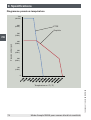
9. Use the torque spanner and tighten the bolts opposite each other
with an initial torque of 34 Nm.
10. Use the torque spanner and tighten the bolts opposite each other
with the nal torque depending on the material.
Final torque for stainless steel: 72 Nm.
Final torque for carbon steel: 87 Nm.

EN
WIKA operating instructions, shut-o valves and valve manifolds
14294094.01 10/2019 EN/DE/FR/ES
15
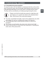
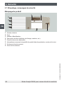
5.2 Commissioning and operation
To close the valve, turn the handle in a clockwise direction as far as the
stop. To open the valve, turn the handle anticlockwise as far as the stop.
It will take approximately 4 turns from open to closed and vice versa.
The ow can be controlled by not totally opening/closing the valve.
Please note that the handle may present a slight play and
spin freely up to a quarter turn when in the depressurised
state. This is due to the constructive design.
■
The valve, especially the handle, must not be subjected to any exter-
nal loading (e.g. use as a climbing aid, support for objects).
■
The handle may only be used by hand; the use of tools is not
accepted.
■
The torque on reaching the valve stop must only be hand-tight.
■
Ensure that all valves of the product are closed prior to opening the
main valve of the process line.
5. Commissioning, operation

EN
14294094.01 10/2019 EN/DE/FR/ES
16 WIKA operating instructions, shut-o valves and valve manifolds
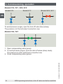
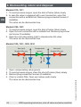
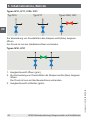
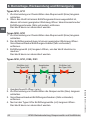
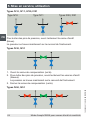
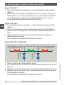
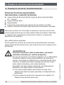
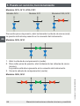
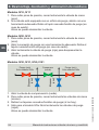
Models IV10, IV11, IV20, IV21
To avoid pressure surges, open the shut-o valve (blue) slowly.
The pressure is at the instrument connection now.
Models IV30, IV31
1. Open compensating valve (green).
2. To avoid pressure surges, open the shut-o valves (blue) slowly.
The pressure is at the instrument connection now.
3. Close compensating valve (green).
Model IV10 Model IV11 Models IV20, IV21
5. Commissioning, operation

EN
WIKA operating instructions, shut-o valves and valve manifolds
14294094.01 10/2019 EN/DE/FR/ES
17
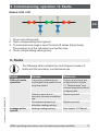
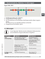
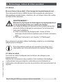
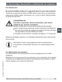
Models IV50, IV51
1. Close vent valves (red).
2. Open compensating valve (green).
3. To avoid pressure surges, open the shut-o valves (blue) slowly.
The pressure is at the instrument connection now.
4. Close compensating valve (green).
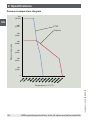
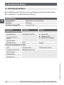
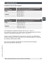
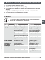
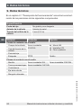
6. Faults
The following table contains the most frequent causes of
faults and the necessary countermeasures.
Faults Causes Measures
Dicult handle
operation
Lubrication problem due to
unchanged valve position for a
long time period
Perform a functional test
as described in chapter
7.1
“Maintenance” and
shorten inspection interval
as appropriate
Defective parts due to
corrosion, process conditions,
age
Replace product
Overtightened gland nut,
defective sealing packing
Replace product
Leakage at the
spindle
Leaking sealing packing See chapter 7.2 “Repair”
5. Commissioning, operation / 6. Faults

EN
14294094.01 10/2019 EN/DE/FR/ES
18 WIKA operating instructions, shut-o valves and valve manifolds
Faults Causes Measures
No ow or
restricted ow of
process media
Valve closed or partially open Ensure that that valve is
open
Incorrect mounting Ensure that that valve is
correctly mounted
Clogging by unsuitable
process media
Check compatibility of
process media
CAUTION!
Physical injuries and damage to property and the
environment
If faults cannot be eliminated by means of the listed
measures, the product must be taken out of operation
immediately.
▶
Ensure that there is no longer any pressure present and
protect against being put into operation accidentally.
▶
Contact the supplier.
▶
If a return is needed, please follow the instructions given in
chapter 8.2 “Return”.
WARNING!
Physical injuries and damage to property and the
environment caused by hazardous media
Upon contact with hazardous media (e.g. oxygen, acetylene,
ammable or toxic substances), harmful media (e.g. corro-
sive, toxic, carcinogenic, radioactive), and also with refriger-
ation plants and compressors, there is a danger of physical
injuries and damage to property and the environment.
Should a failure occur, aggressive media with extremely high
temperature and under high pressure or vacuum may be
present at the product.
▶
For these media, in addition to all standard regulations,
the appropriate existing codes or regulations must also be
followed.
▶
Wear the requisite protective equipment (see chapter 3.6
“Personal protective equipment”).
6. Faults

EN
WIKA operating instructions, shut-o valves and valve manifolds
14294094.01 10/2019 EN/DE/FR/ES
19
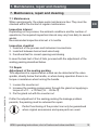
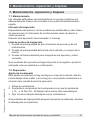
7. Maintenance, repair and cleaning
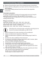
7.1 Maintenance
When used properly, the valves work maintenance-free. They must be
checked within the context of regular maintenance.
Inspection interval
Depending on the process, the ambient conditions and the number of
operations, the required inspection interval may vary from daily to several
weeks.
Recommended inspection interval: ≤ 3 months
Inspection checklist
1. Leak test of the process and instrument connections
2. Leak test between bonnet and valve body
3. Functional test for correct opening and closing
In case the leak test of item 2 fails, proceed with the adjustment of the
sealing packing described below.
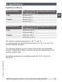
7.2 Repair
Adjustment of the sealing packing
This adjustment is required when a leak can be detected at the valve
spindle, directly below the handle, or when during operation there is no
torque or resistance when turning the handle.
1. Loosen the counter nut
2. Increase the packing compression through the gland nut applying a
torque of ≥13 … ≤ 18 Nm (18 … 25 lbs ft)
3. Fix the gland nut with the counter nut
If after the adjustment of the sealing packing the leakage problem
persists, the packing must be returned for repair.
Perfect functioning of the product can only be guaranteed
when original accessories and spare parts are used.
7. Maintenance, repair and cleaning

EN
14294094.01 10/2019 EN/DE/FR/ES
20 WIKA operating instructions, shut-o valves and valve manifolds
7. Maintenance, repair and cleaning
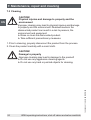
7.3 Cleaning
CAUTION!
Physical injuries and damage to property and the
environment
Improper cleaning may lead to physical injuries and damage
to property and the environment. Residual media in the
dismounted product can result in a risk to persons, the
environment and equipment.
▶
Rinse or clean the dismounted product.
▶
Take sucient precautionary measures.
1. Prior to cleaning, properly disconnect the product from the process.
2. Clean the product carefully with a moist cloth.
CAUTION!
Damage to property
Improper cleaning may lead to damage to the product!
▶
Do not use any aggressive cleaning agents.
▶
Do not use any hard or pointed objects for cleaning.
La page charge ...
La page charge ...
La page charge ...
La page charge ...
La page charge ...
La page charge ...
La page charge ...
La page charge ...
La page charge ...
La page charge ...
La page charge ...
La page charge ...
La page charge ...
La page charge ...
La page charge ...
La page charge ...
La page charge ...
La page charge ...
La page charge ...
La page charge ...
La page charge ...
La page charge ...
La page charge ...
La page charge ...
La page charge ...
La page charge ...
La page charge ...
La page charge ...
La page charge ...
La page charge ...
La page charge ...
La page charge ...
La page charge ...
La page charge ...
La page charge ...
La page charge ...
La page charge ...
La page charge ...
La page charge ...
La page charge ...
La page charge ...
La page charge ...
La page charge ...
La page charge ...
La page charge ...
La page charge ...
La page charge ...
La page charge ...
La page charge ...
La page charge ...
La page charge ...
La page charge ...
La page charge ...
La page charge ...
La page charge ...
La page charge ...
La page charge ...
La page charge ...
La page charge ...
La page charge ...
La page charge ...
La page charge ...
La page charge ...
La page charge ...
La page charge ...
La page charge ...
La page charge ...
La page charge ...
La page charge ...
La page charge ...
La page charge ...
La page charge ...
La page charge ...
La page charge ...
La page charge ...
La page charge ...
La page charge ...
La page charge ...
La page charge ...
La page charge ...
-
 1
1
-
 2
2
-
 3
3
-
 4
4
-
 5
5
-
 6
6
-
 7
7
-
 8
8
-
 9
9
-
 10
10
-
 11
11
-
 12
12
-
 13
13
-
 14
14
-
 15
15
-
 16
16
-
 17
17
-
 18
18
-
 19
19
-
 20
20
-
 21
21
-
 22
22
-
 23
23
-
 24
24
-
 25
25
-
 26
26
-
 27
27
-
 28
28
-
 29
29
-
 30
30
-
 31
31
-
 32
32
-
 33
33
-
 34
34
-
 35
35
-
 36
36
-
 37
37
-
 38
38
-
 39
39
-
 40
40
-
 41
41
-
 42
42
-
 43
43
-
 44
44
-
 45
45
-
 46
46
-
 47
47
-
 48
48
-
 49
49
-
 50
50
-
 51
51
-
 52
52
-
 53
53
-
 54
54
-
 55
55
-
 56
56
-
 57
57
-
 58
58
-
 59
59
-
 60
60
-
 61
61
-
 62
62
-
 63
63
-
 64
64
-
 65
65
-
 66
66
-
 67
67
-
 68
68
-
 69
69
-
 70
70
-
 71
71
-
 72
72
-
 73
73
-
 74
74
-
 75
75
-
 76
76
-
 77
77
-
 78
78
-
 79
79
-
 80
80
-
 81
81
-
 82
82
-
 83
83
-
 84
84
-
 85
85
-
 86
86
-
 87
87
-
 88
88
-
 89
89
-
 90
90
-
 91
91
-
 92
92
-
 93
93
-
 94
94
-
 95
95
-
 96
96
-
 97
97
-
 98
98
-
 99
99
-
 100
100


WIKA IV10 tag:model:IV11 tag:model:IV20 tag:model:IV21 tag:model:IV30 tag:model:IV31 tag:model:IV50 tag:model:IV51 Mode d'emploi
- Catégorie
- Outils électroportatifs
- Taper
- Mode d'emploi
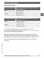
dans d''autres langues
Documents connexes
-
WIKA STW15 Mode d'emploi
-
-
-
-
-
-
-
-
-


