GAI-Tronics IP Access Panel Lite Guide d'installation
- Taper
- Guide d'installation

Pub. 42004-564A
G A I - T R O N I C S ®
A H U B B E L L C O M P A N Y
HUBBCOM™ E3 APLite
TA B L E O F CO N T E N T S
GAI-TRONICS 3030 KUTZTOWN RD. READING, PA 19605 USA
610-777-1374 ◼ 800-492-1212 ◼ Fax: 610-796-5954
VISIT WWW.GAI-TRONICS.COM FOR PRODUCT LITERATURE AND MANUALS
Confidentiality Notice .....................................................................................................................1
General Information .......................................................................................................................1
Important Safety Instructions .........................................................................................................1
Installation ......................................................................................................................................3
Desktop Units .......................................................................................................................................... 3
Wall Mounting ........................................................................................................................................ 4
Single or double gang electrical box mounting: ................................................................................... 4
Surface mounting with toggle bolts or wall anchors: ............................................................................ 4
Wiring ...................................................................................................................................................... 6
Handset ................................................................................................................................................. 6
RTU Input/Output ................................................................................................................................. 6
RS-485 and External Speaker Connections .......................................................................................... 6
Ethernet ................................................................................................................................................. 7
24 V DC Power ..................................................................................................................................... 7
Service and Spare Parts ..................................................................................................................7
Reference Documents .....................................................................................................................7
Specifications ..................................................................................................................................8
Approvals .........................................................................................................................................8

Pub. 42004-564A
G A I - T R O N I C S ®
A H U B B E L L C O M P A N Y
HUBBCOM™ E3 APLite
GAI-TRONICS 3030 KUTZTOWN RD. READING, PA 19605 USA
610-777-1374 ◼ 800-492-1212 ◼ Fax: 610-796-5954
VISIT WWW.GAI-TRONICS.COM FOR PRODUCT LITERATURE AND MANUALS
Confidentiality Notice
This installation manual contains sensitive business and technical information that is confidential and
proprietary to GAI-Tronics. GAI-Tronics retains all intellectual property and other rights in or to the
information contained herein, and such information may only be used in connection with the operation of
your GAI-Tronics product or system. This manual may not be disclosed in any form, in whole or in part,
directly or indirectly, to any third party.
General Information
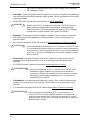
This manual covers installation of the HUBBCOM APLite, Model 319-02-HZ00200. The APLite
includes a handset and is only suitable for horizontal (landscape) installation (see Figure 1). See the
GAI-Tronics website at https://www.gai-tronics.com for application, system specifications, warranty
information, and the GUDA (GAI-Tronics Universal Device Application).
The APLite requires configuration when placed into service Use the GUDA (GAI-Tronics Universal
Device Application) software to configure the APLite for its intended purpose. Pub. 42004-531 provides
instructions to obtain, install, and run the GUDA software. Refer to Pub. 42004-550 for information on
configuring the APLite in an E3 system (see the Reference Documents section).
Important Safety Instructions
•Read, follow, and retain instructions—All safety and operating instructions should be read and
followed before operating the unit. Retain instructions for future reference.
•Heed warnings—Adhere to all warnings on the unit and in the operating instructions.
•Attachments—Attachments not recommended by the product manufacturer should not be used, as
they may cause hazards.
•Servicing—Do not attempt to service this unit by yourself. Opening or removing covers may expose
you to dangerous voltage or other hazards. Refer all servicing to qualified service personnel.
•Indoor Use Only—Do not use HUBBCOM smart controllers in damp or wet locations.
ATTENTION
—Install equipment without modification and according to all applicable local,
national, and international electrical codes. North America—Consult the
National Electrical Code (NFPA 70), Canadian Standards Association (CSA
22.1), and local codes for specific requirements regarding your installation.
Install Class 2 circuit wiring in accordance with the NEC.
Only trained, qualified, and competent personnel must install these enclosures. Installation must comply
with state and national regulations, as well as safety practices for this type of equipment.
WARNING
—Use only 24 V dc power supplies that conform to UL/CSA/CE Class II, Double
Insulated supplies with over voltage and short circuit protection. Use only a dc

Pub. 42004-564A
HUBBCOM™ E3 APLite Page 2 of 8
P:\Standard IOMs - Current Release\42004 Instr. Manuals\42004-564A.docx
01/21
source with a 50-watt maximum output or fuse the supply with a 2-amp fuse.
EMI standards to Class B.
•Onderhoud—Probeer dit apparaat niet zelf te repareren. Het openen of verwijderen van afdekkingen
kan u blootstellen aan gevaarlijke spanning of andere gevaren. Laat alle onderhoud over aan bevoegd
onderhoudspersoneel.
•HUBBCOM Smart Controllers zijn alleen bedoeld voor gebruik binnenshuis.
AANDACHT
—Gebruik alleen 24 VDC-voedingen die voldoen aan UL/CSA/CE Klasse II,
dubbel geïsoleerde voedingen met overspanning en kortsluitbeveiliging.
Gebruik alleen een DC-bron met een maximale output van 50 W of fuseer de
voeding met een 2-ampère zekering. EMI-normen voor klasse B.
•Dépannage—N'essayez pas de réparer cet appareil vous-même. Ouvrir ou retirer les capots peut
vous exposer à des tensions dangereuses ou à d'autres dangers. Confiez toute réparation à un
personnel qualifié.
•Les contrôleurs intelligents HUBBCOM sont conçus pour une utilisation en intérieur uniquement.
ATTENTION
—Utilisez uniquement des alimentations 24 Vcc conformes à UL/CSA/CE Classe
II, des alimentations à double isolation avec protection contre les surtensions et
les courts-circuits. Utilisez uniquement une source cc avec une sortie maximale
de 50 watts ou fusionnez l’alimentation avec un fusible de 2 ampères. Normes
EMI à la classe B.
•Manutenzione—non tentare di riparare l'unità da soli. L'apertura o la rimozione dei coperchi
potrebbero esporre a tensioni pericolose o altri rischi. Rivolgersi a personale qualificato per
l'assistenza.
•Gli HUBBCOM Smart Controller sono progettati esclusivamente per uso interno.
AVVERTIMENTO
—Utilizzare solo alimentatori a 24 V cc conformi a UL/CSA/CE Classe II,
alimentatori a doppio isolamento con protezione da sovratensione e
cortocircuito. Utilizzare solo una fonte di corrente continua con un'uscita
massima di 50 watt o collegare l'alimentazione con un fusibile da 2 A.
Standard EMI per la classe B.
•Mantenimiento—no intente reparar esta unidad por sí mismo. Abrir o quitar las cubiertas puede
exponerlo a un voltaje peligroso u otros peligros. Remita todo el servicio a personal de servicio
calificado.
•Los controladores inteligentes HUBBCOM están diseñados para uso en interiores solamente.
ADVERTENCIA
—Utilice solo fuentes de alimentación de 24 V cc que cumplan con
UL/CSA/CE Clase II, fuentes con doble aislamiento con sobretensión y
protección contra cortocircuitos. Utilice solo una fuente de CC con una
salida máxima de 50 vatios o fusione la fuente con un fusible de 2 amperios.
Estándares EMI a Clase B.

Pub. 42004-564A
HUBBCOM™ E3 APLite Page 3 of 8
P:\Standard IOMs - Current Release\42004 Instr. Manuals\42004-564A.docx
01/21
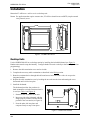
Installation
Mount the E3 APLite to a wall or use it as a desktop unit.
NOTE: For applications that require accurate time, E3 APLites should access an SNTP (simple network
time protocol) server.
Figure 1. HUBBCOM APLite
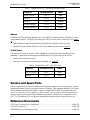
Desktop Units
Use the HUBBCOM APLite as a desktop station by installing the included kickstand (see Figure 2).
Handset units must be setup horizontally. Configure hands-free units vertically or horizontally (based on
programming).
1. Remove the cable termination cover and set it aside.
2. Complete the necessary cable terminations as described in the Wiring section.
3. Route the terminated wires through the half round access holes and secure with a tie wrap to the
integrated anchors.
4. Replace the cable termination cover by hooking the two tabs into the slots and rotating the cover
downward until it clicks into place.
5. Install the kickstand:
The kickstand provides four positions in
both orientations to suit the situation where it
is used (see Table 1 and Figure 4).
1. Determine the orientation of the unit.
2. Insert one side of the kickstand, with the
flange properly oriented, into the desired
position in the rear cutout (see Figure 4).
3. Press the other side into place and
compress firmly to snap it into place.
Figure 2. Hubbcom Kickstan
d

Pub. 42004-564A
HUBBCOM™ E3 APLite Page 4 of 8
P:\Standard IOMs - Current Release\42004 Instr. Manuals\42004-564A.docx
01/21
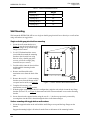
Table 1. APLite Kickstand Positions
Position Angle
1 (flange up) 75°
2 (flange up) 60°
2 (flange down) 45°
3 (flange up) 30°
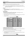
Wall Mounting
Wall mount the HUBBCOM APLite on a single or double gang electrical box or directly to a wall surface
using wall anchors or toggle bolts.
Single or double gang electrical box mounting:
1. Orient the wall-mount bracket (see
Figure 3) over the electrical box with
the small flanges on top and the large
flanges on the bottom.
2. Use #8-32 flathead machine screws
(not included) to attach the mounting
bracket to the electrical box using
holes A-A for a double gang (four
screws), or B-B for a single gang
electrical box (two screws).
3. Feed the cable(s) into the electrical box
and through the mounting bracket
center hole.
4. Remove and discard the cable
termination cover from the back of the
unit.
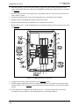
5. Remove the two #8 × ½-inch mounting
bracket screws from the bottom of the
rear panel and set aside (see Figure 4).
6. Complete all necessary cable
terminations (see the Wiring section).
7. With the proper orientation for the unit’s configuration, angle the unit to hook it onto the top flange
brackets (D-D or E-E, see Figure 4), then rotate and slide it downward until it rests on the mounting
bracket.
8. Secure the unit to the support bracket using the two #8 × ½-inch screws previously removed by
screwing them into the unit’s chassis through the holes in the bottom flanges.
Surface mounting with toggle bolts or wall anchors:
1. Orient the support bracket on the wall with the small flanges on top and the large flanges on the
bottom.
Suggested mounting height is 48 inches from the floor to the bottom of the mounting bracket.
Figure 3. Smart Controller Wall-Mount Bracket

Pub. 42004-564A
HUBBCOM™ E3 APLite Page 5 of 8
P:\Standard IOMs - Current Release\42004 Instr. Manuals\42004-564A.docx
01/21
2. Mark the locations (C) for the four wall anchors or toggle bolts (not included) and the area in the
center of the bracket where the cable(s) come through the wall using the support bracket as a template
(see Figure 3).
3. Drill the necessary holes for the toggle bolts or wall anchors and cut or drill a hole in the center area
for the APLite’s cables.
4. Attach the mounting bracket to the wall using toggle bolts or wall anchors (not included).
5. Bring the cable(s) out through the support bracket center cutout.
6. Remove and discard the cable termination cover from the back of the unit.
7. Remove the two #8 × ½-inch mounting bracket screws from the bottom of the rear panel and set aside
(see Figure 4).
Figure 4. HUBBCOM APLite—Rear View
8. Complete all necessary cable terminations (see the Wiring section).
9. With the proper orientation for the unit’s configuration, angle the unit to hook it onto the top flange
brackets (D-D or E-E, see Figure 4), then rotate and slide it downward until it rests on the mounting
bracket.
10. Secure the unit to the support bracket using the two #8 × ½-inch screws previously removed by
screwing them up into the unit’s chassis through the holes in the bottom flanges.

Pub. 42004-564A
HUBBCOM™ E3 APLite Page 6 of 8
P:\Standard IOMs - Current Release\42004 Instr. Manuals\42004-564A.docx
01/21
Wiring
HUBBCOM APLites have quick release terminal blocks that accept 18–24 AWG wires. Release wires
from the terminal block by pressing the quick release button above the terminal.
NOTE: Two clamp on ferrite cores are supplied with the unit. Double wrap all wires terminating to
terminal blocks TB1 and/or TB2 around a ferrite core. Install the clamp on ferrite cores as close
as possible to the terminal blocks.
Handset
1. Plug the RJ12 handset connector into the RJ12 jack on the back of the unit.
2. Wall-mount installation—Tuck the handset cord into the channel to provide strain relief for the
RJ12 plug.
RTU Input/Output
Terminal Block TB1 is for optional RTU I/O (Remote Terminal Unit Input/Output) functionality.
Complete the following steps to terminate the RTU I/O cables:
1. Install appropriately sized ferrules onto the wire ends.
2. Install a clamp on ferrite core around all wires (double wrap) terminating to TB1 as close as possible
to the terminal block.
3. Insert each wire into the correct quick release terminal (see Table 2).
Table 2. Terminal Block TB1—RTU I/O
Purpose
Term-Block Pin
Label
RTU Input One Ground
TB1-1
GND
RTU Input One
TB1-2
IN1
RTU Input Two Ground
TB1-3
GND
RTU Input Two
TB1-4
IN2
RTU Output One +
TB1-5
OUT1+
RTU Output One −
TB1-6
OUT1(−)
RTU Output Two −
TB1-7
OUT2(−)
RTU Output Two +
TB1-8
OUT2+
RS-485 and External Speaker Connections
Terminal Block TB2 is for optional RS-485 and external speaker connections. Complete the following
steps to terminate the RS-485 and external speaker connections:
NOTE: APLites with external speaker hook-ups require a separate 24 V dc power supply.
1. Install appropriately sized ferrules onto the wire ends.
2. Install a clamp on ferrite core around all wires (double wrap) terminating to TB2 as close as possible
to the terminal block.
3. Insert each wire into the correct quick release terminal (see Table 3).

Pub. 42004-564A
HUBBCOM™ E3 APLite Page 7 of 8
P:\Standard IOMs - Current Release\42004 Instr. Manuals\42004-564A.docx
01/21
Table 3. Terminal Block TB2—RS-485 and External Speaker
Purpose
Term-Block Pin
Label
RS485 Ground
TB2-1
GND
RS485 B
TB2-2
RS485B
RS485 A
TB2-3
RS485A
External Speaker −
TB2-4
SPKR−
External Speaker +
TB2-5
SPKR+
Ethernet
HUBBCOM APLites have dual Ethernet ports. Use the RJ45 jack furthest from the USB port to connect
to the Ethernet network. The RJ45 jack closest to the USB port can be used to connect a PC (see Figure
4).
1. Plug the Ethernet cable from the network into the RJ45 port furthest from the USB port.
2. (Optional) Plug an Ethernet cable from a PC into the remaining RJ45 jack(see Figure 4).
24 V DC Power
Use external 24 V dc power in place of POE (optional) or for units with external speaker hook-ups
(required). Complete the following steps to terminate the 24 V dc power source to the APLite:
1. Install ferrules onto the wire ends.
2. Insert each wire into the correct quick release terminal (see Table 4).
Table 4. Terminal Block TB3—24 V DC Power
Purpose
Term-Block Pin
Label
24 V dc Positive
TB3-1
+24V
Ground
TB3-2
GND
Service and Spare Parts
Contact a regional service center for assistance if the equipment requires service or spare parts. A return
authorization number (RA#) will be issued if service is required. Ship equipment prepaid to GAI-Tronics
with an RA# and a purchase order number. Repair or a replacement is made in accordance with GAI-
Tronics’ warranty policy if the equipment is under warranty. Please include a written explanation of all
defects to assist our technicians in their troubleshooting efforts. Call 800-492-1212 inside the USA or
610-777-1374 outside the USA for help with identifying the Regional Service Center closest to you.
Reference Documents
GAI-Tronics Universal Device Application .................................................................................. 42004-531
E3 Console Version 3.0 ................................................................................................................. 42004-550
HUBBCOM Device Configuration Guide ..................................................................................... 42004-551

Pub. 42004-564A
HUBBCOM™ E3 APLite Page 8 of 8
P:\Standard IOMs - Current Release\42004 Instr. Manuals\42004-564A.docx
01/21
Specifications
Wi-Fi operating frequency range ........................................................................................ 2.412–2.462 GHz
Temperature Range ............................................................................................. 32 °F–122 °F (0 °C–50 °C)
Approvals
Compliance to Standard
CE
EMC emissions to Class B ....................................................................... EN55032/FCC Part15B/ICES-003
Immunity .......................................................................................................................................... EN55035
Assessment risk of exposure ............................................................................................................ EN62311
Product Safety Assessment .................................................................................................. UL/IEC62368-1
Contains FCC ID: Z64-WL18DBMOD and IC: 4511-WL18DBMOD
NOTE: This equipment has been tested and found to comply with the limits for a Class B digital device, pursuant to
part 15 of the FCC Rules. These limits are designed to provide reasonable protection against harmful
interference in a residential installation. This equipment generates, uses, and can radiate radio frequency
energy and, if not installed and used in accordance with the instructions, may cause harmful interference to
radio communications. However, there is no guarantee that interference will not occur in a particular
installation. If this equipment does cause harmful interference to radio or television reception, which can
be determined by turning the equipment off and on, the user is encouraged to try to correct the interference
by one or more of the following measures:
•Reorient or relocate the receiving antenna.
•Increase the separation between the equipment and receiver.
•Connect the equipment into an outlet on a circuit different from that to which the receiver is connected.
•Consult the dealer or an experienced radio/TV technician for help.
-
 1
1
-
 2
2
-
 3
3
-
 4
4
-
 5
5
-
 6
6
-
 7
7
-
 8
8
-
 9
9


GAI-Tronics IP Access Panel Lite Guide d'installation
- Taper
- Guide d'installation
dans d''autres langues
Documents connexes

Autres documents
-
Eaton DG1-357D6FB-C21C Communications Manual
-
Güde 5 T UG Le manuel du propriétaire
-
Agri-Fab 45-04621 Le manuel du propriétaire
-
-
Philips SWV4132W/10 Product Datasheet
-
Lego 42004 Technic Building Instructions
-
Liebert EXL Guide d'installation
-
Eaton 9395C-1100/1100 Mode d'emploi
-