
Mellanox Technologies
Third party information brought
to you courtesy of Dell.
InfiniScale® IV 16+16 Port 40Gb/s
InfiniBand Switch for Dell PowerEdge
M1000e-series Blade Enclosures User Manual
PN: M3601Q
Rev 1.1

Rev 1.1 Mellanox Technologies
2
Copyright 2009. Mellanox Technologies, Inc. All Rights Reserved.
Mellanox Technologies ConnectX, InfiniBlast, InfiniBridge, InfiniHost, InfiniRISC, InfiniScale, and
InfiniPCI are registered trademarks of Mellanox Technologies, Ltd. Virtual Protocol Interconnect is a trade
-
mark of Mellanox Technologies, Ltd. Dell and the Dell logo are trademarks of Dell Inc. All other marks and
names mentioned herein may be trademarks of their respective companies.
InfiniScale® IV 16+16 Port 40Gb/s InfiniBand Switch for Dell PowerEdge M1000e-series Blade
Enclosures User Manual
Document Number: 3010
Mellanox Technologies, Inc.
350 Oakmead Parkway Suite 100
Sunnyvale, CA 94085
U.S.A.
www.Mellanox.com
Tel: (408) 970-3400
Fax: (408) 970-3403
Mellanox Technologies Ltd
PO Box 586 Hermon Building
Yokneam 20692
Israel
Tel: +972-4-909-7200
Fax: +972-4-959-3245
NOTE:
THIS INFORMATION IS PROVIDED BY MELLANOX FOR INFORMATIONAL PURPOSES ONLY AND ANY
EXPRESS OR IMPLIED WARRANTIES, INCLUDING, BUT NOT LIMITED TO, THE IMPLIED WARRANTIES OF
MERCHANTABILITY AND FITNESS FOR A PARTICULAR PURPOSE ARE DISCLAIMED. IN NO EVENT SHALL
MELLANOX BE LIABLE FOR ANY DIRECT, INDIRECT, INCIDENTAL, SPECIAL, EXEMPLARY, OR CONSE
-
QUENTIAL DAMAGES (INCLUDING, BUT NOT LIMITED TO, PROCUREMENT OF SUBSTITUTE GOODS OR
SERVICES; LOSS OF USE, DATA, OR PROFITS; OR BUSINESS INTERRUPTION) HOWEVER CAUSED AND ON
ANY THEORY OF LIABILITY, WHETHER IN CONTRACT, STRICT LIABILITY, OR TORT (INCLUDING NEGLI
-
GENCE OR OTHERWISE) ARISING IN ANY WAY OUT OF THE USE OF THIS HARDWARE, EVEN IF ADVISED
OF THE POSSIBILITY OF SUCH DAMAGE.

M3601Q 16+16 Port 40Gb/s InfiniBand Switch User Manual
Mellanox Technologies Rev 1.1
3
Contents
Contents 3
About this Manual 4
Revision History 5
Chapter 1 Overview 6
1.1 InfiniBand Connectors 7
1.2 Switch Status Lights 8
Chapter 2 Installation and Basic Operation 9
2.1 Installation Safety Warnings 9
2.2 Mechanical Installation 11
2.2.1 Removing an Old Switch From the Chassis 11
2.2.2 Removing an I/O Module Blank From the Chassis 12
2.2.3 Installing the Mellanox M3601Q Switch Into the Dell Chassis 12
2.3 Power Connections and Initial Power On 12
2.4 InfiniBand Cable Installation 12
Chapter 3 Cluster Management and Firmware 14
3.1 Network Management and Clustering Software 14
3.2 Updating Firmware 14
3.2.1 Instructions for Reprogramming Over the InfiniBand Network 14
Chapter 4 Troubleshooting 17
Appendix A Specification 18
Appendix B EMC Certification Statements 19
Appendix C QSFP Interface 21
Appendix D Avertissements de sécurité d’installation 23
Appendix E Installation - Sicherheitshinweise 25

M3601Q 16+16 Port 40Gb/s InfiniBand Switch User Manual
Mellanox Technologies Rev 1.1
4
About this Manual
This manual describes the installation and basic use of the Mellanox M3601Q 16+16 Port 40Gb/s
InfiniBand Switch for Dell PowerEdge M1000e-series Blade Enclosures.
Intended Audience
This manual is intended for users and system administrators responsible for installing and setting
up the switch platforms listed above.
The manual assumes familiarity with the InfiniBand® Architecture Specification.
Related Documentation
The documentation set accompanying the Mellanox M3601Q includes the following:
Online Resources
• Mellanox Technologies Web pages: http://www.mellanox.com
• Dell Support Web pages: http://support.dell.com
Conventions
Throughout this manual, the name M3601Q and the terms switch, I/O module, and IOM are used to
describe the 16+16 port 40Gb/s InfiniBand switch for the Dell M1000e, unless explicitly indicated
otherwise.
Table 1 - Reference Documents
InfiniBand Architecture Specification Vol-
ume 1 Release 1.2.1 and Volume 2 release
1.2.1
InfiniBand architecture specification descriptions
Mellanox Firmware Tools (MFT)
User’s Manual
Document # 2329
The MFT (Mellanox Firmware Tools) package is a set of firmware tools. The manual
supplied with this package provides an overview of the firmware its installation and
replacement. The MFT can be downloaded with its documentation at:
http://www.mellanox.com > Downloads > Firmware Tools.

M3601Q 16+16 Port 40Gb/s InfiniBand Switch User Manual
Mellanox Technologies Rev 1.1
5
Revision History
Table 2 - Revision History Table
Date Revision Description
March 2009 1.1 Added Dell Logo
November 2008 1.0 Initial Release

M3601Q 16+16 Port 40Gb/s InfiniBand Switch User Manual
Mellanox Technologies Rev 1.1
6
1 Overview
The Mellanox M3601Q 40Gb/s InfiniBand Switch Blade for Dell PowerEdge M1000e-series Blade
Enclosures provides a high bandwidth, low latency fabric for Enterprise Data Centers, High-Perfor
-
mance Computing and Embedded environments. Based on the fourth generation InfiniScale® IV
InfiniBand switch device, this I/O module (IOM) delivers up to 40Gb/s full bisectional bandwidth
per port. When used in conjunction with ConnectX® InfiniBand dual port Mezzanine I/O cards,
clustered data bases, parallelized applications and transactional services applications will achieve
significant performance improvements resulting in reduced completion time and lower cost per
operation.
The I/O module comes pre-installed with all necessary firmware, and configured for standard oper-
ation within an InfiniBand fabric, and requires an InfiniBand compliant Subnet Manager running
from one of the hosts. All that is required for normal operation is to follow the usual precautions for
installation and connection from the switch to the HCAs or other switches. Once connected, the
Subnet Management software automatically configures and begins utilizing the switch.
It is recommended that Mellanox OpenFabrics software package be installed on all nodes con-
nected to the M3610Q. The software package provides a subnet manager and network management
tools as well as connectivity software for servers and storage, and is available on the Mellanox web
site. See Chapter 3 for more information.
Basic installation, hot-swapping components and hardware maintenance is covered in “Installation
and Basic Operation” on page 9.
The M3601Q switch has a Hot Swap controller and a PSOC Management IC.

Rev 1.1 Mellanox Technologies
7
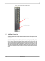
Figure 1: Switch Front Panel and Locking Mechanism
1.1 InfiniBand Connectors
InfiniBand connectivity has 16 QSFP connectors through the front panel. The remaining 16 inter-
faces are through the AirMax Midplane Connector out the back of the switch. Figure 1 shows the
front 16 ports.
Each of the InfiniBand ports has two LEDs located next to the connector. The green LED, when lit,
indicates that a valid physical connection to the other system (switch or HCA port) exists. The yel
-
low LED when lit, indicates that the Subnet Manager is running and a valid data link exists. The
yellow LED illuminates when the InfiniBand network is discovered over the physical link. A valid
data activity link without data transfer is designated by a constant yellow LED indication. A valid
data activity link with data transfer is designated by a blinking yellow LED indication. If the LEDs
are not active, either the physical link or the logical link (or both) connections have not been estab
-
lished.
Locking Mechanism
Switch Status Lights

M3601Q 16+16 Port 40Gb/s InfiniBand Switch User Manual
Mellanox Technologies Rev 1.1
8
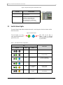
Figure 2: Physical and Logical Link Indication LEDs
1.2 Switch Status Lights
The switch Status lights indicate whether the switch is receiving power from the chassis, and the
state of the switch.
Figure 3: Indicator LEDs
Table 3 - IOM states and LED configurations:
LED
Switch Status
Indication Green Status
OFF OFF OFF
ON OFF Boot in Progress
Switch not ready
Blinking Blue
ON BLINKING BLUE The CMC is identifying
the newly installed switch
ON ON BLUE Switch is on and operating Normally
ON ON or BLINKING
AMBER
Fault in System
Self-diagnosed
OFF ON or BLINKING
AMBER
Fault in System
CMC-detected
LED Name Connection Status
Physical Link - Green Off – No Physical Link
ON – Physical Link
Data Activity - Yellow Blinking – indicates Data Transfer
Constant on – indicates Link exists
with no Data Transfer taking place
Off with green LED lit – indicates that
the Subnet Manager may not be running
The IO Module is on and
ready when both the blue and
green LEDs are lit.
This LED can be blue or
amber. A fault is indicated
when the amber LED is blink-
ing. See Table 3.

Rev 1.1 Mellanox Technologies
9
2 Installation and Basic Operation
Installation and initialization of the I/O module are straightforward processes, requiring attention to
the normal mechanical, power, and thermal precautions for rack-mounted equipment. The I/O mod
-
ule does not require any programming or configuration to operate as a basic InfiniBand switch and
includes all of the necessary functionality to operate with external standard InfiniBand Subnet
Management software.
This section describes the installation process and basic operation of the I/O module. Please first
read the warnings sub-section carefully before carrying on with installation procedures.
2.1 Installation Safety Warnings
1. Installation Instructions
2. Over-temperature
3. Stacking the Chassis
4. During Lightning - Electrical Hazard
Suitable electrical, mechanical and fire enclosure shall be provided by the end user.
Read all installation instructions before connecting the equipment to the power source.
This equipment should not be operated in an area with an ambient temperature exceed-
ing the maximum recommended: 40°C (104°F). Moreover, to guarantee proper air flow,
allow at least 8cm (3 inches) of clearance around the ventilation openings.
The chassis should not be stacked on any other equipment. If the chassis falls, it can
cause bodily injury and equipment damage.
During periods of lightning activity, do not work on the equipment or connect or discon-
nect cables.

M3601Q 16+16 Port 40Gb/s InfiniBand Switch User Manual
Mellanox Technologies Rev 1.1
10
5. Copper InfiniBand Cable Connecting/Disconnecting
6. Rack Mounting and Servicing
7. Equipment Installation
8. Equipment Disposal
9. Local and National Electrical Codes
Copper InfiniBand cables are heavy and not flexible, as such they should be carefully
attached to or detached from the connectors. Refer to the cable manufacturer for special
warnings and instructions.
When this product is mounted or serviced in a rack, special precautions must be taken to
ensure that the system remains stable. In general you should fill the rack with equipment
starting from the bottom to the top.
This equipment should be installed, replaced, or serviced only by trained and qualified
personnel.
Disposal of this equipment should be in accordance to all national laws and regulations.
This equipment should be installed in compliance with local and national electrical
codes.

Rev 1.1 Mellanox Technologies
11
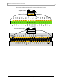
2.2 Mechanical Installation
These switches are hot pluggable. It is not necessary to power down the Dell Chassis to install a
new switch or to replace an old switch with a new one.
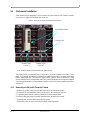
Figure 4: Rear View of the Dell PowerEdge M1000e Chassis
Note: M3601Q blades are not allowed in the Fabric A slots.
The M3601Q IOM occupies both Fabric B and Fabric C slots and connects to the Fabric C mid-
plane. The ConnectX Mezzanine I/O card must be installed in the Fabric C location on the server
blade to support data flow. This does NOT apply to DDR, since the switch is installed in a single
slot and connected to a its corresponding fabric the ConnectX Mezzanine I/O card must be installed
in the corresponding fabric. You must install a module in slots B1/C1 before installing a module in
slots B2/C2.
2.2.1 Removing an Old Switch From the Chassis
1. Remove any locking cables or screws that secure the old switch into the chassis.
2. Disconnect all of the InfiniBand cables from the front of the switch to be removed.
3. Unlock the switch from the chassis by pushing the red latch release button.
4. Pull the locking arm down to a position perpendicular to the front of the chassis.
5. Pull the switch out of the chassis using the locking arm.
• Install either a new switch or an I/O Module Blank within one minute.
Latch Release Buttons
Locking Arms
Channel 2 slots
C2 B2 A2
Channel 1 slots
A1 B1 C1

M3601Q 16+16 Port 40Gb/s InfiniBand Switch User Manual
Mellanox Technologies Rev 1.1
12
2.2.2 Removing an I/O Module Blank From the Chassis
1. Unlock the I/O Module Blank by pushing the red latch release button.
2. Pull the locking arm down to a position perpendicular to the front of the chassis.
3. Pull the I/O Module Blank out of the chassis using the locking arm.
4. Install either a new switch or reinstall a blank IOM within one minute.
2.2.3 Installing the Mellanox M3601Q Switch Into the Dell Chassis
Note: Make sure the rack is stable on a solid floor and that the rack is filled from the bottom up.
This will keep the center of gravity as low as possible reducing risk of tipping.
Note: The M3601Q I/O module occupies both Fabric B and Fabric C slots and connects to the
Fabric C mid-plane. The ConnectX I/O card must be installed in the Fabric C location on the
server blade to support data flow. You must install a module in slots B1/C1 before installing a
module in slots B2/C2.
Refer to the Dell PowerEdge M1000e Hardware Owners Manual for more information.
1. Follow the instructions in Section 2.2.1 or Section 2.2.2 to remove an old switch or an I/O Mod-
ule Blank.
2. On the new switch, push the red latch release button.
3. Pull the lever forward until the lever is perpendicular to the front panel.
4. Push the switch into the slot until the latching mechanism is against the bar.
5. Push the lever on the latching mechanism up, making sure that the latching mechanism catches
the locking bar. The lever should now be parallel to the front panel.
6. Check the indicator lights to make sure the switch has power.
The rack mounting is designed to fit the PowerEdge M1000e Chassis. Take precau-
tions to guarantee proper ventilation for air intake at the front of the chassis and
exhaust at the rear in order to maintain good airflow at ambient temperature. Cable
routing in particular should not impede the air exhaust from the chassis.
2.3 Power Connections and Initial Power On
Caution: The I/O module will automatically power up when AC power is applied. There is no
power switch. Immediately upon closing the latching mechanism check to make sure that the
green switch LED is lit.
2.4 InfiniBand Cable Installation
All cables can be inserted or removed with the unit power on. To insert a cable, press the connector
into the port receptacle until the connector is firmly seated. The green LED indicator accompanying
each port will light when the physical connection is established (that is, when the unit is powered
on and a cable is plugged into the port with a functioning port plugged into the other end of the con
-
nector). After plugging in a cable, lock the connector using the latching mechanism particular to the
cable vendor. The yellow LED will light if the subnet manager is running (non blinking indicating
that no data is being transferred yet). When a logical connection is made the yellow LED will blink
signifying data is being transferred.

Rev 1.1 Mellanox Technologies
13
To remove, disengage the locks and slowly pull the connector away from the port receptacle. Both
LED indicators will turn off when the cable is unseated.
Care should be taken not to impede the air exhaust flow through the chassis.
Note: Cable lengths should be used which allow for routing horizontally around to the side of the
chassis before bending upward or downward in the rack.

M3601Q 16+16 Port 40Gb/s InfiniBand Switch User Manual
Mellanox Technologies Rev 1.1
14
3 Cluster Management and Firmware
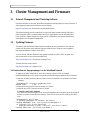
3.1 Network Management and Clustering Software
Download and install, on all nodes, the Mellanox OpenFabric software package for Linux, Windows, or
other operating systems from the Mellanox software website:
http://www.mellanox.com >Downloads > InfiniBand SW/Drivers.
This software package provides connectivity for server and storage systems utilizing High Perfor-
mance Computing (HPC) or enterprise data center (EDC) applications across an InfiniBand fabric.
It also provides a Subnet Manager for simple network configuration and network administration
and diagnostic tools for network management.
3.2 Updating Firmware
The switch is delivered with the latest Firmware available at the time of production. New firmware
versions will be posted on the Mellanox firmware download page. Firmware can be updated in-
band using the Mellanox Firmware Tools (MFT).
You will need the Mellanox Firmware Tools package available in MLNX_OFED to update firm-
ware for this switch. It also can be downloaded from:
http://www.mellanox.com > Downloads > Firmware Tools.
The latest firmware can be found at:
http://www.mellanox.com > Support > Dell.
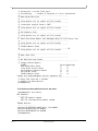
3.2.1 Instructions for Reprogramming Over the InfiniBand Network
To update an MT48436 InfiniScale IV switch device having a specific GUID (for example,
0x00000006660abcd0) or LID, the following are the recommended steps to update the device firmware.
1. Make sure all subnet ports are in the active state. One way to check this is to run opensm, the Subnet
Manager.
[root@mymach]> /etc/init.d/opensmd start
opensm start [ OK ]
2. Make sure the local ports are active by running ‘ibv_devinfo’.
3. Obtain the device LID. There are two ways to do that:
I. Using the “mst ib add” command:
The “mst ib add”runs the ibdiagnet tool to discover the InfiniBand fabric and then lists the discovered IB
nodes as an mst device under /dev/mst/ directory. These devices can be used for access by other MFT
tools.
[root@mymach]> mst ib add
-I- Running ibdiagnet to discover the fabric ...
Loading IBDIAGNET from: /usr/local/lib/ibdiagnet1.2
-W- Topology file is not specified.
Reports regarding cluster links will use direct routes.
Loading IBDM from: /usr/local/lib/ibdm1.2

Rev 1.1 Mellanox Technologies
15
-I- Using port 1 as the local port.
-I- Discovering ... 3 nodes (2 Switches & 1 CA-s) discovered.
-I---------------------------------------------------
-I- Bad Guids/LIDs Info
-I---------------------------------------------------
-I- skip option set. no report will be issued
-I---------------------------------------------------
-I- Links With Logical State = INIT
-I---------------------------------------------------
-I- skip option set. no report will be issued
-I---------------------------------------------------
-I- PM Counters Info
-I---------------------------------------------------
-I- skip option set. no report will be issued
-I---------------------------------------------------
-I- Fabric Partitions Report (see ibdiagnet.pkey for a full hosts list)
-I---------------------------------------------------
-I- skip option set. no report will be issued
-I---------------------------------------------------
-I- IPoIB Subnets Check
-I---------------------------------------------------32
-I- skip option set. no report will be issued
-I---------------------------------------------------
-I- Bad Links Info
-I---------------------------------------------------
-I- No bad link were found
----------------------------------------------------------------
-I- Stages Status Report:
STAGE Errors Warnings
Bad GUIDs/LIDs Check 0 0
Link State Active Check 0 0
Performance Counters Report 0 0
Partitions Check 0 0
IPoIB Subnets Check 0 0
Please see /tmp/ibdiagnet.log for complete log
----------------------------------------------------------------
-I- Done. Run time was 1 seconds.
-I- Added 3 in-band devices
[root@mymach]>
To list the discovered mst inband devices run “mst status”.
[root@mymach]> mst status
MST modules:
------------
MST PCI module loaded
MST PCI configuration module loaded
...
Inband devices:
-------------------
/dev/mst/CA_MT25418_sw005_HCA-1_lid-0x0001
/dev/mst/SW_MT47396_lid-0x0011
/dev/mst/SW_MT48438_lid-0x0003
[root@mymach]>

M3601Q 16+16 Port 40Gb/s InfiniBand Switch User Manual
Mellanox Technologies Rev 1.1
16
II. Using the ibnetdiscover tool:
Run:
[root@mymach]# ibnetdiscover | grep 00000006660abcd0 | grep -w Switch
Switch 24 "S-00000006660abcd0" "MT48436 Infiniscale-III Mellanox Technologies"
base port 0 lid 17 lmc 0
Note: The resulting LID is given as a decimal number.
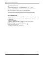
4. Run mlxburn with the LID retrieved in step #3 above to perform the In-Band burning operation.
Burn the InfiniScale IV switch:
[root@mymach]> mlxburn -d /dev/mst/SW_MT48438_lid-0x0003 -fw ./fw-IS4.mlx -qq
-I- Querying device ...
-I- Using auto detected configuration file: ./MTS3600Q-1UNC_A1.ini (PSID =
MT_0C20110003)
-I- Generating image ...
*** WARNING *** Running quick query - Skipping full image integrity checks.
Current FW version on flash: 7.0.135
New FW version: 7.0.138
Burning second FW image without signatures - OK
Restoring second signature - OK
-I- Image burn completed successfully.

Rev 1.1 Mellanox Technologies
17
4 Troubleshooting
As soon as a switch is plugged in make sure that the power LED comes on.
The power LED for the switch does not come on:
1. Check that the chassis has power.
2. Remove and reinstall the switch.
The status LED for the switch is blinking amber:
1. remove the switch from the chassis and re-insert it (verify that the switch is all the way in the
chassis and the lever is firmly closed).
2. If the amber LED continues to blink, replace the switch.
The link LED for the InfiniBand connector does not come on:
1. Check that both ends of the cable are connected.
2. Check that the locks on the ends are secured.
3. Make sure that the latest FW version is installed on both the Mezzanine I/O card and the switch.
4. Make sure that at least one blade has a matching Mezzanine I/O card installed to support data
flow.
5. If media adapters are used check that the all connections are good, tight, and secure.
The activity LED does not come on:
Check that the Subnet Manager has been started.
The power LED for the switch shuts off:
1. Check that the there is adequate ventilation.
2. Make sure that there is nothing blocking the front or rear ventilation openings of the chassis.

M3601Q 16+16 Port 40Gb/s InfiniBand Switch User Manual
Mellanox Technologies Rev 1.1
18
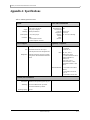
Appendix A: Specifications
Table 4 - M3601Q Specification Data
Physical Power and Environmental
H x W x D:
Weight:
Mounting:
SerDes Speeds
Connectors:
10.73 x 2.322 x 10.04 inches
272.54 x58.98 x 255.02 mm
3.05 Kg fully configured
Vertically mounted rack
10, 20, 40 Gb/s per port
QSFP
16 external QSFP connectors
16 internal backplane connectors
Maximum Power:
Dissipated Power:
Power through
connector:
Temperature:
Humidity:
Altitude:
Shock:
Vibration:
152 W
120W
2.0 W per port
0°C to 40°C
10% - 90% non-condensing
Protocol Support Regulatory Compliance
InfiniBand:
QoS:
Management:
Auto-Negotiation of 10Gb/s, 20Gb/s, or 40 Gb/s
9 InfiniBand Virtual Lanes for all ports
8 Data transport lanes and 1 management lane
Baseboard, Performance, and Device manage-
ment Agents for full InfiniBand In-Band Man-
agement
Safety:
EMC:
ENVIRONMENTAL
US/Canada: cTUVus
EU: IEC60950
International: CB
USA: FCC, Class A
Canada: ICES, Class A
EU: CE Mark (EN55022 Class A,
EN55024, EN61000-3-2,
EN61000-3-3)
Japan: VCCI, Class A
Korea: RRL (MIC), Class A
Australia/New Zealand: C-Tick
Class A
EU: IEC 60068-2-64: Random
Vibration
EU: IEC 60068-2-29: Shocks,
Type I / II
EU: IEC 60068-2-32: Fall Test
Scalability and Performance
Switching
Performance:
Addressing:
Switching Capacity
Simultaneous wire-speed any port to any port
48K Unicast Addresses Max. per Subnet
16K Multicast Addresses per Subnet
2.56 Tb/s

Rev 1.1 Mellanox Technologies
19
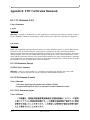
Appendix B: EMC Certification Statements
B.1: FCC Statements (USA)
Class A Statements:
§ 15.21
Statement
Warning! Changes or modifications to this equipment not expressly approved by the party responsi-
ble for compliance (Mellanox Technologies) could void the user's authority to operate the equipment.
§15.105(a)
Statement
NOTE: This equipment has been tested and found to comply with the limits for a Class A digital device,
pursuant to Part 15 of the FCC Rules. These limits are designed to provide reasonable protection
against harmful interference when the equipment is operated in a commercial environment. This equip-
ment generates, uses, and can radiate radio frequency energy and, if not installed and used in accor-
dance with the instruction manual, may cause harmful interference to radio communications. Operation
of this equipment in a residential area is likely to cause harmful interference in which case the user will
be required to correct the interference at his own expense.
B.1.1 EN Statements (Europe)
EN55022 Class A Statement:
Warning! This is a class A product. In a domestic environment this product may cause radio
interference, in which case the user may be required to take adequate measures.
B.1.2 ICES Statements (Canada)
Class A Statement:
“This Class A digital apparatus complies with Canadian ICES-003.
Cet appareil numérique de la classe A est conforme à la norme NMB-003 du Canada.”
B.1.3 VCCI Statements (Japan)
Class A Statement:

M3601Q 16+16 Port 40Gb/s InfiniBand Switch User Manual
Mellanox Technologies Rev 1.1
20
(Translation - "This is a Class A product based on the standard of the Voluntary Control
Council for Interference by Information Technology Equipment (VCCI). If this equipment is
used in a domestic environment, radio interference may occur, in which case the user may be
required to take corrective actions.")
B.1.4 MIC Certification (Korea)
Korea's "Regulation for Certification of Information and Communication Equipment," requires EMC test-
ing and certification for many electronic products. Korean EMC certifications are issued by Radio
Research Laboratory (RRL), which is organized under the Ministry of Information and Communications
(MIC). EMC testing includes electromagnetic emissions (EMI) and susceptibility (EMS). Certified equip
-
ment is labeled with the MIC mark and certification number.
Translation:
Class A Device This device is registered for EMC requirements for industrial use. The seller or buyer
should be aware of this. If this type was sold or purchased by mistake, it should be replaced with a res-
idential-use type.
La page est en cours de chargement...
La page est en cours de chargement...
La page est en cours de chargement...
La page est en cours de chargement...
La page est en cours de chargement...
La page est en cours de chargement...
-
 1
1
-
 2
2
-
 3
3
-
 4
4
-
 5
5
-
 6
6
-
 7
7
-
 8
8
-
 9
9
-
 10
10
-
 11
11
-
 12
12
-
 13
13
-
 14
14
-
 15
15
-
 16
16
-
 17
17
-
 18
18
-
 19
19
-
 20
20
-
 21
21
-
 22
22
-
 23
23
-
 24
24
-
 25
25
-
 26
26


Mellanox Technologies PowerEdge M420 Manuel utilisateur
- Taper
- Manuel utilisateur
- Ce manuel convient également à
dans d''autres langues
Documents connexes
-
Dell InfiniScale III M2401G 20Gb/s InfiniBand Manuel utilisateur
-
Mellanox Technologies MIS5024Q-1BRR Manuel utilisateur
-
Mellanox Technologies ConnectX-3 Pro MCX349A-XCCN Manuel utilisateur
-
-
Mellanox Technologies MCX453A-FCAT Manuel utilisateur
-