Mantis 7940 Le manuel du propriétaire
- Catégorie
- Mini motoculteurs
- Taper
- Le manuel du propriétaire

OPERATOR’S/PARTS MANUAL
MAN 430131
Rev. C 3-31-20
Operator’s Manual and Safety Instructions for
Tiller/Cultivator
Tiller/Cultivator
MODEL 7940
MODÈLE 7940
Motobêche-bineuse
Manuel de l'utilisateur et consignes de
sécurité pour la motobêche-bineuse
MANUEL DE L'UTILISATEUR / PIÈCES DÉTACHÉES

2 Operator’s Manual
IMPORTANT MESSAGE
Thank you for purchasing this Schiller Grounds Care, Inc. product. You have purchased a world-class product, one of the best designed and built anywhere.
This machine comes with Operation and Safety instructions, Parts and Service instructions, and Engine instructions. The useful life and good service you
receive from this machine depends to a large extent on how well you read and understand these manuals. Treat your machine properly, lubricate and adjust it
as instructed, and it will give you many years of reliable service.
Your safe use of this Schiller Grounds Care, Inc. product is one of our prime design objectives. Many safety features are built in, but we also rely on your good
sense and care to achieve accident-free operation. For best protection, study the manuals thoroughly. Learn the proper operation of all controls. Observe all
safety precautions. Follow all instructions and warnings completely. Do not remove or defeat any safety features, and make sure those who operate this machine
are as well informed and careful in its use as you are.
See a Schiller Grounds Care, Inc. dealer for any service or parts needed. Schiller Grounds Care, Inc. service ensures that you continue to receive the best
results possible from Schiller Grounds Care, Inc. products. You can trust Schiller Grounds Care, Inc. replacement parts, because they are manufactured with
the same high precision and quality as the original parts.
Schiller Grounds Care, Inc. designs and builds its equipment to serve many years in a safe and productive manner. For longest life, use this machine only as
directed in the manuals, keep it in good repair, and follow all safety warnings and instructions. You’ll always be glad you did.
Schiller Grounds Care, Inc.
1028 Street Road
Southampton, PA 18966-4217
PHONE (800) 366-6268 • FAX (215) 956-3855
SAFETY RULES & WARNINGS
Special Safety Information ................................................. 3
Safety & Warnings ............................................................. 3
Safety Decal Information ................................................... 3
Warning Dos ...................................................................... 4
Warning Don’ts .................................................................. 5
Engine/Fuel Warning Dos .................................................. 5
Engine/Fuel Warning Don’ts .............................................. 5
ASSEMBLY ............................................................................6
Lower Handle .................................................................... 7
Upper Handle Assembly .................................................... 8
Tines ...............................................................................8-9
Kickstand ........................................................................... 9
FUELING & STARTING
4-Cycle Fueling & Oil Only .............................................. 10
4-Cycle Corrective Action ................................................ 10
4-Cycle Starting Only ....................................................... 10
OPERATION .................................................................... 11-12
TRANSPORTATION ............................................................. 13
STORAGE ............................................................................ 13
MAINTENANCE ..............................................................14-16
TROUBLESHOOTING ......................................................... 17
MANTIS TILLER ASSEMBLY & PARTS LIST .................18-19
LIMITED WARRANTY INFORMATION ................BACK PAGE
TABLE OF CONTENTS
Welcome to the World of Mantis Gardening
Here’s your new MANTIS Tiller . . . the lightweight wonder that’s Changing the
Way Americans Garden.
®
Unlike big tillers, your MANTIS Tiller weighs only 24 lbs. (Model 7940). So it lifts
easily, handles smoothly, and tills and weeds precisely. And unlike other small
tillers, it features serpentine tines that churn soil to 10” deep, creating a soft,
smooth seed bed, even in problem soil.
Once you know how to use your tiller correctly, we guarantee you’ll love it. So rst, please read this manual. It shows, step by
step, how to use your tiller safely.
ATTENTION MANTIS PRODUCT OWNERS!
Get maintenance tips for your Mantis
product on our web site
at www.mantis.com
This Operator’s/Parts Manual is part of the machine. Suppliers of both new and
second-hand machines must make sure that this manual is provided with the machine.

3Contact us at www.mantis.com
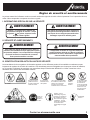
You will notice Safety Rules and Important Notes throughout this Operator’s Manual. Make sure you understand and obey these
warnings for your own protection.
I. SPECIAL SAFETY INFORMATION
II. SAFETY & WARNINGS
III. SAFETY DECAL INFORMATION
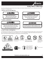
An important part of the safety system incorporated in this tiller is the warning and information decals found on various parts of the
tiller. These decals can degrade in time due to abrasion, etc. It is your responsibility to replace these decals when they become
hard to read. Please review and familiarize yourself with each o the following decals:
Safety Rules & Warnings
Improper use or care of this tiller or failure to wear
proper protection can result in serious injury.
Read and understand the rules for safe
operation and all instructions in this manual.
Wear hearing and eye protection.
To reduce the potential for accidents, comply
with the safety instructions in this manual.
Failure to comply may result in serious
personal injury, and/or equipment
and property damage.
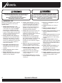
The engine exhaust from this product contains
chemicals known to the State of California to cause
cancer, birth defects or other reproductive harm.
Attention: This symbol points out our
important safety instructions.
When you see this symbol,
heed it’s warning!! Stay alert!!
P/N 430057
P/N 400631
Cutting hazard; keep
feet and hands away
from rotating tines.
Don’t operate
indoors
Caution: when assembling
the handles, make sure
fuel tank faces away from
operator. This is the rear of
the tiller, refer to assembly
instruction on page 8-9.
Incorrect assembly.
Wear ear
and eye
Protection.
Do not carry the
tiller in this position.
Read owner’s manual before
using tiller, or performing any
repair or maintenance. Keep
owners manual in a safe place.
Don’t fuel, refuel,
or check fuel while
smoking, or near an
open ame or other
ignition source.

4 Operator’s Manual
If the tiller is used improperly or safety precautions
are not followed, the users risk serious injury
to themselves and others.
Read and understand this manual before
attempting to operate this tiller.
Operation of this equipment may create sparks
that can start res around dry vegetation. A spark
arrestor is installed. The operator should contact
local re agencies for laws or regulations relating
to re prevention requirements.
IV. WARNINGS - DO
Read and understand the owner’s manual.
Pay particular attention to all sections
regarding safety.
1. Always keep a rm grip on both
handles while the tines are moving and/
or the engine is running. BE AWARE!
The tines may continue to spin after
throttle trigger is released and continue
to pose a hazard. Make sure tines have
come to a complete stop and engine is
off before letting go of the tiller.
2. Always maintain a rm footing and
good balance. Do not overreach while
operating the tiller. Before you start to
use the tiller, check the work area and
remove any obstacles that might cause
you to lose your footing, balance, or
control of the machine.
3. Thoroughly inspect the area where
equipment is to be used and remove
all objects that can be thrown by the
machine.
4. Always keep area clear of children,
pets, and bystanders.
5. Always stay alert. Watch what you are
doing and use common sense. Do not
operate unit when fatigued.
6. Always dress properly. Do not wear
loose clothing or jewelry that could get
caught in moving parts. Use sturdy
gloves to reduce the transmission of
vibration to your hands, as prolonged
exposure to vibration can cause
numbness and other ailments.
7. Always wear substantial footwear and
long trousers while working. Do not
operate the equipment when barefoot or
wearing open-toe sandals.
8. Always wear ear and eye protection.
Eye protection must meet applicable
CE or ANSI standards. To avoid hearing
damage, we recommend hearing
protection be worn whenever using the
equipment.
9. Keep the engine and petrol/gas storage
area free of vegetative material and
excessive grease to reduce re hazard.
10. Start the engine carefully, according
to all manufacturer’s instructions and
with feet well away from tool(s).
11.
Keep all nuts, bolts and screws tight
to be sure the equipment is in safe
working condition.
12.
Use extreme caution when reversing
the tine direction or pulling the machine
toward you.
13. Work only in daylight or with good
articial light.
14. Always be sure of your footing on
slopes.
15. Exercise extreme caution when
changing direction on slopes.
16. Always keep a safe distance between
two or more people when working
together.
17. Always inspect your tiller before each
use. Tighten all loose hardware to be
sure the equipment is in safe working
condition.
18. Always visually inspect to ensure
that the tools are not worn or damaged.
Before using your tiller, replace worn or
damaged elements and bolts in sets to
preserve balance.
19. Always maintain and examine your
tiller with care. Follow maintenance
instructions given in manual.
20. Always store tiller in a sheltered area
(a dry place) not accessible to children.
21. Always remember the operator or user
is responsible for accidents or hazards
occurring to other people or their
property.

5Contact us at www.mantis.com
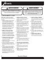
Handle fuel with care, it is highly ammable. Fueling a hot engine or near an ignition source can
cause a re and result in serious personal injury and/or property damage.
Safety Rules & Warnings
VI. ENGINE/FUEL WARNINGS - DO
VII. ENGINE/FUEL WARNINGS - DON’T
Always use fresh gasoline. Stale gasoline
can cause damage.
Always store fuel in containers
specically designed for this purpose.
Always add fuel before starting
the engine.
Always replace all fuel tank and
container caps securely.
Always pull starter cord slowly until
resistance is felt to avoid kickback and
prevent arm or hand injury.
Always operate engine with spark
arrestor installed and operating properly.
Stop the engine whenever you leave
the machine and before refueling. Allow
the engine to cool before storing in any
enclosure. Replace worn or damaged
parts for safety.
Only drain the fuel tank outdoors. To
reduce the potential of re. Keep the
engine and fuel storage area free of
vegetative material and excessive
grease.
Never pick up or carry a machine while
the engine is running or the tines are
turning.
Don’t fuel, refuel, or check fuel while
smoking, or near an open ame or other
ignition source. Stop engine and be sure
it is cool before refueling.
Don’t leave the engine running while the
tiller is unattended. Stop the engine when
carrying out maintenance and cleaning
operations, when changing tools, or
when being transported by any means
other than under the tiller’s own power.
Never remove the fuel cap or add fuel
while the engine is running or when the
engine is hot.
Don’t refuel, start, or run this tiller
indoors or in an improperly ventilated
area.
Don’t run engine if electrical system
causes sparks outside the cylinder.
During periodical checks of the spark
plug, keep plug a safe distance from
cylinder to avoid burning evaporated fuel
from cylinder.
Don’t check for spark with spark plug
or plug wire removed. Use an approved
tester.
Don’t crank engine with spark plug
removed unless spark plug wire is
disconnected. Sparks can ignite fumes.
Don’t run engine when the odor of gasoline
is present or other explosive conditions exist.
Don’t
attempt to start the engine if fuel is
spilled. Move the machine away from the
area of spillage and avoid creating
any spark or source of ignition until fuel
vapors have dissipated or spill has been
cleared.
Don’t operate your tiller if there is an
accumulation of debris around the mufer
or cooling ns.
Don’t touch hot mufers, cylinders or
cooling ns contact may cause serious
burns.
Don’t change the engine governor
setting or over throttle the engine.
Don’t attempt to remove spark plug while
engine is hot. Removing a spark plug
from a hot engine can cause irreparable
damage to the engine and will void your
warranty.
Don’t use starter uids they will cause
permanent engine damage.
V. WARNINGS - DON’T
Don’t use tiller with one hand. While the
tines are moving or engine is running,
keep both hands on handles with ngers
and thumbs encircling the handles.
Don’t run with the machine, walk.
Don’t work on steep slopes.
Never attempt to clear tines while they
are moving, or the engine is running.
Switch the engine off and make sure the
tines have stopped completely before
removing jammed material.
Don’t allow children or people unfamiliar
with these instructions to use the
machine. Local regulations can restrict
the age of operator.
Don’t let others operate tiller without
proper training.
Never store the tiller or its fuel in a
house.
Don’t operate while under the inuence
of alcohol or drugs.
Don’t attempt to repair this tiller. Have
repairs made by a qualied dealer or
repairman. See that only original Mantis
parts are used.
Don’t overreach. Keep a good footing at
all times.
Don’t stand in front of tiller when tines
are rotating or engine is running.

6 Operator’s Manual
Assembly
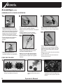
WHAT COMES IN THE BOX
WHAT YOU WILL NEED
TO ASSEMBLE THE TILLER
Prior to removing the contents and assembling, it is important to:
• Have a clean work area
• Make sure all necessary
tools are handy
• Have two 7/16” wrenches
• Have a 3/8” wrench for
kickstand assembly
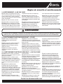
Improper assembly of this tiller can result in serious injury. Make
sure to follow all instructions carefully. If you have any questions,
contact our factory at 1-800-366-6268 or an authorized Mantis dealer.
Key Qty. Part No. Description
T1 1 Upper Handle Throttle Side Assembly
T2 1 Upper Handle Assembly, Left
T3 2 Lower Handles W/Plug
T4 1 Handle Brace Assembly
T10 1 Plastic Carrying Handle
T21, T20,
T46
1 Engine Assembly (includes Fender Guard &
Worm Gear Transmission)
T39/T40 1 Pair Tiller/Cultivator Tines
1 Bag of Hardware
T7 2 Handle Clamps
T9 1 Throttle Clip
T11 2 Bolts (3” long)
T12 2 Knobs
T13 2 Acorn Nuts
T14 4 Lock Nuts
T15 2 Cap Screws
T41 2 Tine Retaining Pins
T42 2 Carriage Bolts
T49 1 Kickstand, Stand Assembly
T50 1 Kickstand, Bracket and Hardware Bag
Not Shown
1 400206 4-Cycle Oil
Bag Contents
Picture of Model 7940
T40
T41
T41
T4
T10
T15
T15
T39
T1
T3
T20 T46T21
T2
T12
T12
T9
T13
T13
T7
T7
T9
T11
T11
T14
T42
T49
T50
T42
T14

7Contact us at www.mantis.com
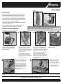
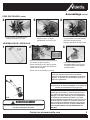
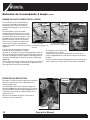
LET’S BEGIN
• With the box upright, open the box and remove the
tine box and the loose parts at the top of the tiller
box. Do not remove any other parts from the box.
• Lay the box on one side and open the bottom aps.
• Return the box to an upright position (as shown in
Figure A) and pull the box straight up.
• Leave the engine and throttle handle in the cradle to
assist in the assembly.
• Lay everything out so you can easily identify the
parts (see parts image and list on page 6).
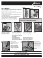
Assembly
• Slide the lower handles that
you’ve just put together into
the two recessed channels.
• Make sure you insert them
from the rear of the tiller
(gasoline tank faces away
from the operator) so the
bolt ts along the back of
the housing.
• Slide the second 3-inch
bolt (T11) through the
second set of holes in
the short legs. Add a
lock
nut (T14)
and tighten
nger tight until you’ve
completed assembly.
LOWER HANDLE ASSEMBLY
• For ease of assembly and
stability, it is important that you
keep the engine assembly in its
cardboard cradle.
1
6
• Lay all handle parts within easy
reach. You’ll need one of the
handle clamps (T7) and one of
the lower handles (T3). Note that
the lower handles have a short
leg on one end.
• Fit the handle clamp along
the outside of the short leg as
shown. Line up the holes on the
clamp and the leg.
2
• Choose one of the two 3-inch bolts
(T11). Slide it through the rst set
of holes near the elbow where the
lower handle curves. (Pictures 2 & 3)
• Now slide the other lower handle
onto the 3-inch bolt. Fit the other
clamp onto the other handle’s
short leg. Add a lock nut (T14) and
tighten “nger tight” (as tight as you
can make them without the use of a
tool). (Picture 3)
3
• Locate recessed channels
below the engine.
4
5
NOTE: THE LOCK NUTS ARE STAMPED. FINGER TIGHT IS APPROXIMATELY 1/2 TO 1-1/2 TURNS UNTIL YOU’VE COMPLETED ASSEMBLY.
See page 6 to identify part numbers.
NOTE: Some of the photos in this manual do not represent your
tiller engine. They are for assembly purposes only.
Figure A
Figure B

8 Operator’s Manual
Assembly (Continued)
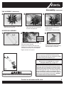
UPPER HANDLE ASSEMBLY
• Lightly squeeze the lower
handles (T3) toward one another
so they line up with the two
smaller holes on the carrying
handle (T10). Then slide the
carrying handle over and down
the lower handles. It will rest
about four to six inches above the
fender.
• Gently pull the lower handles out
to their original position.
• Your Mantis tiller will look like
this when the lower handle
assembly is complete.
7a
7b
• You will need the two tines and two retaining
pins.
• Remove the unit from the
cardboard cradle and lay the
unit on its side.
• You will notice that one side of the
tine has a circular hole, while the
other has a D-shaped hole.
TINE ASSEMBLY
1 2 3
8
• Lift the upper handle until the holes
line up with the lower handle.
•
Insert carriage bolt (T42) from outside in.
• Screw on knob (T12) and fully tighten
the knob at the pivot point.
• Repeat steps 8 and 9 to install the
other upper handle onto the other
lower handle.
• Use throttle clip (T9) to secure the
throttle cable and wire in place on the
lower handle.
10
9
• Cap the exposed bolt with an acorn
nut (T13) and tighten with your 7/16”
wrench until snug. Do not over tighten.
• Line it up holes on handle brace (T4)
with the holes on the upper handles.
Insert a cap screw (T15) and a lock nut
(T14) on either side.
• Use a wrench to tighten cap screws
and lock nuts.
• Use wrench to tighten all nuts and
bolts rmly and securely.
11

9Contact us at www.mantis.com
Assembly (Continued)
• Attach the tine so that the circular hole
slides onto the axle rst.
• When the axle protrudes from the
other side it will line up perfectly
with the D-shaped hole.
4 5
• Position the kickstand brace just above the
bend of the lower handles.
• Position the kickstand under the lower
handles, line up the holes, and thread the
kickstand brace bolts into the kickstand.
•Tighten with the 3/8” wrench.
• Your Mantis tiller will look like
this when lower handle assembly
and kickstand are complete.
KICKSTAND ASSEMBLY
1 2 3
IMPORTANT NOTE:
Be sure you have proper throttle movements and that
the throttle cable is not wrapped or twisted around the
handle bar. Hold down the lockout lever, fully squeeze
the throttle trigger and let go. The throttle triangle must
click in both directions. If there is any doubt, remove
air lter and visually check that the throttle triangle hits
both the idle screw and the full open stop. THIS MUST
BE DONE BEFORE STARTING THE ENGINE.
IMPORTANT NOTE:
Before you use your MANTIS Tiller, read the
Safety Rules & Warnings on pages 3-5
IMPORTANT NOTE:
Make sure you have installed the handles properly.
When you stand behind your tiller, holding the handles,
the fender warning label should face you.
Improper Throttle installation can cause tines to rotate unexpectedly.
7940
TINE ASSEMBLY (Continued)
• Slide a tine retaining pin (T41)
through the hole in the axle to
secure the tine.
• Repeat steps for the other side.
6

10 Operator’s Manual
Fuel is extremely ammable. Handle it with
care. Keep away from ignition sources. Do not
smoke while fueling your equipment
Do not operate the engine in a conned
space where dangerous carbon monoxide
fumes can collect.
Avoid accidental blade engagement.
Do not squeeze the throttle trigger when starting. Main-
tain proper idle speed adjustment (2500-3100 rpm)
WARNING • DANGER
ALTERNATIVE FUELS, SUCH AS E-15 (20% ETHANOL), E-85 (85% ETHANOL)
OR ANY FUELS NOT MEETING HONDA REQUIREMENTS ARE NOT APPROVED
FOR USE IN GASOLINE ENGINES. USE OF ALTERNATIVE FUELS MAY CAUSE
PERFORMANCE PROBLEMS, LOSS OF POWER, OVERHEATING, FUEL VAPOR
LOCK AND UNINTENDED MACHINE OPERATION, INCLUDING, BUT NOT LIMITED
TO, IMPROPER CLUTCH ENGAGEMENT. ALTERNATIVE FUELS MAY ALSO CAUSE
PREMATURE DETERIORATION OF FUEL LINES, GASKETS, CARBURETORS AND
OTHER ENGINE COMPONENTS.
! !
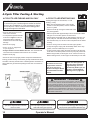
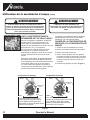
4-Cycle Tiller Fueling & Starting
4-CYCLE TILLER FUELING AND OIL ONLY
• Rock the tiller forward so that it
rests on the fuel tank.
• It is important to position the tiller
as shown in Figure 1 so the oil
will properly ll the crankcase.
Failure to do so will cause engine
damage.
• Remove the oil plug.
• Pour in 2.7 . oz. of approved,
4-cycle engine oil.
• Always check the oil level before each use. The oil level should
reach the inner rst thread of the reservoir. Do not overll.
• Replace the oil plug.
• Return the unit to the upright position and put the kickstand down.
Fueling your tiller is easy. Unscrew the gas cap and ll the tank about
four-fths of the way with 89 octane unleaded gasoline. Remember to
always drain the gas when transporting the unit from one location to
another.
4-CYCLE TILLER STARTING ONLY
Starting the engine for the rst time, or “cold
starting”, is easy.
• Make sure the start/stop switch on the throttle
handle is in the start position, which is indicated
by the “I” symbol.
• Close the choke by moving the choke lever to the
up (closed) position.
• Press the primer bulb approximately 6 times until he bulb is lled
with gas. Once it is lled, press it two more times.
• Pull the starter cord lightly until you feel resistance, then give it a
short, brisk pull. Your tiller should start immediately. Do not pull
the cord all the way out, and do not let it snap back into the starter
housing.
•
Once it is running, move the choke to the down (open) position.
• To stop the engine, simply push the start/stop switch to the stop
position, which is indicated by the “O” symbol.
• To start a warm engine, follow the same procedure, but leave the
choke lever in the down position and do not pump the primer bulb.
• Before using the tiller, let the engine run for a minute to warm up.
Before shutting it down, let the engine run idle briey to cool down.
OFF ON
Switch
IMPORTANT NOTE:
Check the oil level in the
engine before each use.
If oil is low see your 4
Stroke Tiller Engine Manual
and information at left for
details.
Never use starting uids, as
they will cause permanent
engine damage, and void
the warranty. Before you use
the tiller, read the Safety &
Warning rules on pages 3-5.
IMPORTANT!
It is normal for your 4 stroke engine to smoke for the rst
minute or two of operation. It is not necessary for this to
occur every time. This is a result of the oil being pulled
through the engine for lubrication.
Figure 1

11Contact us at www.mantis.com
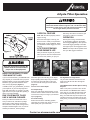
4-Cycle Tiller Operation
Read the instructions carefully. Be
familiar with the controls and the
proper use of the equipment.
A SPECIAL FEATURE
Note: With the idle set properly and the
engine running
Even when the engine is running, the
tines won’t turn unless you squeeze the
throttle trigger on the handlebars. When
you release the throttle trigger, the tines
will stop
.
A TIP FOR EXTENDING
YOUR ENGINE’S LIFE
After you start the engine, let your tiller
warm up for two to three minutes before
you use it. Then, before you put your
tiller away, let it idle for a minute to give
the engine a chance to cool down.
OPERATION
With engine running, and both hands
on the handles, hold down the throttle
lockout trigger (Figure 1), then squeeze
the throttle trigger gradually to increase
the engine speed and engage the tines.
NOTE: This step must be repeated each
time your tiller trigger is released.
NOW YOU’RE READY TO USE
YOUR MANTIS TILLER.
If you’ve used other tillers, your MANTIS Tiller
may surprise you. It tills best when you pull it
backward! When you pull your MANTIS Tiller
backward, you give extra resistance to the
tines, so they dig deeper. (Figure 2)
In addition, when you go backward, you erase
your footprints, so your soil stays light and
uffy. With other tillers, by contrast, you walk
right over the soil you’ve just tilled, packing it
down, so it’s less plantable.
RUN YOUR MANTIS TILLER
LIKE A VACUUM CLEANER
Place your Tiller at the head of the row or
area you want to till, and start it up. Begin
with an easy rocking motion, and pull the
Tiller backward. Then repeat rocking motion,
and pull it backward again. Then, let it move
forward just a little bit, before pulling it
backward again. This will help you till deeper.
Keep repeating these steps until you’ve tilled
an entire row, then start again on the next
row. It’s
much like running a vacuum cleaner!
(Figure 3)
You can even control depth.
For deeper tilling:
Move your Tiller slowly back and forth, as you
would a vacuum cleaner. Work the same area
over and over until you’ve dug to your desired
depth. (Figure 4)
For shallow tilling:
Switch the tines to the cultivating position
(See page 12 to learn how). Then move your
Tiller quickly over your soil surface.
For Big Weeds or Tough Roots:
Let your Tiller rock back and forth over the
tough spot until the tines slice through the
weed or root.
Your MANTIS Tiller Handles Special Tilling
Projects:
Want to turn part of your lawn into a colorful
ower border? Your MANTIS Tiller makes it
easy! Just run your Tiller back and forth until
the sod begins to break up. Then continue
tilling. Your Tiller will chop the clumps of sod
until they’re ne then work them into the soil.
Pretty soon, you’ll have a soft, fresh planting
bed.
Figure 2 Figure 3 Figure 4
Figure 1
WARNING
ALWAYS MAKE SURE THE HANDLE KNOBS ARE
SECURE BEFORE STARTING YOUR MANTIS TILLER.
! !
If engine does not stop when switch is put in the stop position,
release the throttle and allow engine to idle. Put the tiller down
and slide the choke lever to the cold start (closed) position. Do
not use again before product is serviced.

12 Operator’s Manual
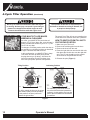
YOUR MANTIS TILLER MAKES
WEEDING A PLEASURE!
As a tiller, your MANTIS Tiller works the soil
down to 10” (25.4 cm) deep. But, as a cultivator it
gently cultivates the surface to just 2” to 3” (5.09
cm to 7.62 cm) deep.
To change to cultivating mode, switch the tines to
the weeding (or cultivating) position as described
at right. This takes less than a minute.
In this conguration, your MANTIS Tiller’s sharp
“tine teeth” will slice up those pesky weeds,
burying them as you go along. And since the
tines in this position won’t dig too deep, they
won’t hurt your plants’ precious root systems.
The result? Your Tiller will cut your weeding time
in half and turn a tiresome chore into a pleasure.
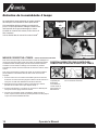
HOW TO SWITCH FROM TILLING TO
CULTIVATING POSITION
1. Make sure your Tiller is off.
2. Remove the retaining pins from the tines.
3. Remove the tines from the axle.
4. Place the right-side tine onto the left-side axle,
then place the left side tine onto the right-side
axle. The “D” hole should be to the outside
when the tines are positioned correctly.
5. Reinsert the pins. (Figure 1)
4-Cycle Tiller Operation (Continued)
The operator of this tiller is responsible for
accidents or hazards occurring to himself, oth-
er people or their property.
Never try to remove an obstruction while the engine
is running. Serious injury can result. If your tines get
jammed or entangled, shut off the engine at once.
Remove the obstruction while the engine is off.
For tilling, attach the tines so the points
face forward (away from the operator).
In this position, the tines’ points will
contact the ground rst.
For cultivating, reverse the tines so
the points face backward (toward the
operator). In this position, the long at
part of the tine’s blade will contact the
ground rst.
Tilling Position Cultivating Position
Figure 1
Figure 1

13Contact us at www.mantis.com
Before storing your Mantis Tiller for
any long period, be sure to take these
measures:
1. Do not store your Tiller with fuel still in
it. Even under ideal conditions, stored
fuel containing ethanol or MTBE can
start to go stale in 30 days. Stale fuel
has a high gum content and can clog
the carburetor, restricting fuel ow.
When you’re ready to store your
Tiller, or will not be using it for
more than two weeks, drain the fuel
tank completely.
2. To make sure no fuel is left in the
carburetor, restart the engine. Then
run the engine until it stops. This will
prevent gum deposits from forming
inside of the carburetor and possibly
damaging the engine.
3. Disconnect spark plug wire and
remove the spark plug. Apply a
couple of drops of clean engine oil
into the cylinder. Install the top cover
temporarily. Pull the starter grip
several times to distribute the oil in the
cylinder.
4. Inspect the spark plug. If necessary,
clean it. Replace it with a NGK-
CMR5H spark plug if damaged or
badly fouled, if the sealing washer is
in poor condition or if the electrode is
worn.
5. Replace the spark plug, but leave the
spark plug wire disconnected.
6. Wipe the tines with oil or spray them
with WD-40 to prevent rusting.
7. Oil the throttle cable and all visible
moving parts. (Do not remove the
engine cover.)
8. Clean or replace the air lter.
9. Inspect the fuel lter. If the fuel lter
is dirty, wash it gently with non-
ammable or high ash point solvent.
If the fuel lter is excessively dirty,
replace it.
10. Check the grease level in the worm
gear housing. Add grease if needed.
11. Store your Tiller in an upright position
in a clean, dry place.
You can hang it using the handle
brace, or store with the handles in
an extended position or folded down.
To fold the handles down, loosen the
lower two-pronged knobs until you
can pivot the upper handles down.
(Figure 2)
12. If you have fuel left over from last
season, dispose of it properly. Buy
fresh oil and gasoline next season.
13. Remove Tilling tines or attachments
and lightly oil tine shaft at least once
a year.
4-Cycle Tiller Transportation & Storage
Never store the equipment
with fuel in the tank or in
an area where fumes may
accumulate and breach an
open ame or spark
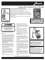
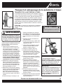
4-CYCLE TILLER TRANSPORTATION
Transporting your Tiller is easy. It’s light and easy to carry using
the carrying handle as shown in Figure 1.
Or with it running, you can walk it by gently squeezing the
throttle until it moves at a comfortable pace. Your Tiller is also
easily transported in the back of a car or truck. Be sure to empty
the fuel tank (This is crucial)! Then stow your tiller in the trunk of
your car or truck.
CAUTION: You must empty your Tiller’s fuel tank before placing
it in a car or truck.
TILLER STORAGE
Figure 2
Figure 2
WARNING
NEVER CARRY YOUR TILLER AS THE PERSON IN
FIGURE 2 IS DOING. IF YOU DO, YOU WILL SUFFER
SERIOUS INJURY.
! !
IMPORTANT:
It is important to store your 4-Cycle
Mantis Tiller in an upright position.
Laying the Tiller on its side will
cause the oil to leak out of the engine
through the air cleaner case.
IMPORTANT:
Avoid placing the Tiller with the top
cover (engine head) down. This can
allow oil from the crankcase to enter
the combustion chamber and cause
hard starting or a locked piston.
Figure 1

14 Operator’s Manual
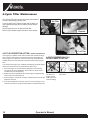
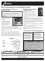
4-Cycle Tiller Maintenance
Air Filter
Dipstick
Your 4-Cycle Tiller will require some basic maintenance
to keep it performing year after year.
If you are storing your Tiller for longer than 30 days, it is
very important to empty the fuel tank to prevent engine
damage.
Check engine oil level, air lter and fuel lter.
Refer to your Honda
®
engine manual for more details.
Fuel Filter
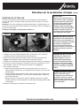
If the engine is overlled, oil will enter the crankcase and will not simply
pour out of the oil ll opening. The excessive oil must be pumped out
as the engine runs. Check the oil level and drain any excess between
multiple 30-second running intervals to bring the oil back to the proper
level.
If you suspect the engine oil is overlled, the following procedure should
remove the excess oil from the crankcase and valve cover.
1. Place the engine on a level surface (resting at on the fuel tank)
and remove the oil ll cap/dipstick. Use a bucket to collect oil that
overows from the oil ll opening.
2. Replace the oil ll cap/dipstick and run the engine for approximately
30 seconds, then repeat step one.
3. Continue steps 1 & 2 until oil no longer overows when the oil ll cap/
dipstick is removed.
4. Once the overlled oil is removed, continue to run the engine. It may
continue to smoke for several minutes while the residual oil burns off.
4-CYCLE PROPER OIL FILL/
LEVEL CHECK POSITION
Engine must be resting on the fuel tank on a
at surface
This position does
not allow for a
proper oil level
reading and may
cause overlling.
4-CYCLE CORRECTIVE ACTION: OVERFILLED ENGINE OIL

15Contact us at www.mantis.com
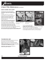
4-Cycle Tiller Maintenance (Continued)
A wet or dirty air lter can affect the way your engine starts, performs, and wears.
Check your air lter once a month or after every 10 hours of use.
Note: If you work in dusty soil, check your lter more often (for instance, before
each use). Be sure to replace it if its worn out or damaged.
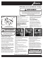
How to Check, Clean, and Change the Air Filter
AIR FILTER MAINTENANCE
Figure 1 Figure 2
1. The air lter is held in the air cleaner in a black housing on the side of the Tiller,
behind the gas tank cap.
2. Squeeze the two locking tabs at the rear of the air cleaner cover (Figure 1) and
swing the cover toward the front of the engine to open it.
3. The air lter is the dark, sponge-like material on the inside of the air cleaner.
4. If the air lter needs to be cleaned (i.e. if it is soiled or moist), or no longer ts
properly, simply remove it by carefully peeling it out of the air cleaner. (Figure 2)
5. To clean the air lter
a. Clean the lter element in warm, soapy water then rinse and allow to dry
thoroughly. It also can be cleaned with a non-ammable solvent.
b. Dip the lter element in clean engine oil then squeeze out any excess oil.
Note: The engine will smoke when started if too much oil is left in the element.
c. Wipe dirt from the air cleaner body and cover using a moist rag. Note: Be
careful to prevent dirt from entering the carburetor.
6. Replace the clean lter inside the air cleaner.
IMPORTANT:
Make sure the lter is “seated”
properly in the cover. The lter
must t snugly inside the open-
ing that holds the lter in place.
Installing the lter incorrectly will
cause engine damage and void
the warranty. Fit the cover back
over the air cleaner and snap the
two locking tabs.
IMPORTANT NOTE:
A dirty air cleaner will restrict air
ow to the carburetor, reducing
engine performance. If you oper-
ate the engine in very dusty areas,
clean the air lter element more
often then specied in the
Maintenance section.
IMPORTANT NOTE:
Operating the engine without an
air lter element, or with a dam-
aged air lter element, will allow
dirt to enter the engine, causing
rapid engine wear. This type of
damage is not covered by the
Limited Warranty
IMPORTANT NOTE:
Check the lip on the Air
Cleaner Cover. If the lip is chipped
or cracked, it should be replaced.
This will prevent dirt from being
drawn through the carburetor into
the inside of the engine.

16 Operator’s Manual
Note: Check the transmission grease level after the
rst 10 hours of use, then check yearly.
With the tines off, remove the transmission plate
(Figure 3) and gasket to see if the grease level is up
to the plate ange (Figure 4). If it is not, you will need
to add lithium zero or lithium one grease.
Wipe off any excess grease and replace the
transmission gasket and plate.
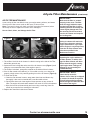
If the tines won’t turn when you press
the throttle, it may mean the engine isn’t
seated all the way down on the worm gear
housing.
If you have been using your Tiller for
several years or if you have removed the
engine for use with our hedge trimmer
attachment and then replaced it, the
ange bolt may have come loose and
lifted the engine up.
In this case you’ll notice a gap between the
bottom of the engine clutch case and the
top of the worm gear housing. (Figure 1)
To eliminate the gap, loosen the ange
bolt and take the engine off the worm gear
housing. Notice the hex head on top of the
drive shaft and locate the clutch drum inside
the clutch case. Make sure the hex head lines up with the
clutch drum inside the clutch case. (Figure 5)
Next, put the engine back on the worm gear housing, making
sure the plastic carrying handle is not under the fuel tank.
If you’ve followed these steps
properly, there will be no gap
between the clutch case and the worm gear housing. (Figure
2) Finally, make sure to tighten the ange bolt.
All other engine maintenance issues are addressed in the
Honda
®
Engine Manual included in your Tiller package.
Note how the engine doesn’t
sit all the way down on the
transmission.
HOW TO RESEAT THE FLANGE
TRANSMISSION CARE
Note how the engine sits
all the way down on the
transmission.
Hex head on top of the drive shaft
Clutch drum inside the clutch case
4-Cycle Tiller Maintenance (Continued)
Figure 3
Figure 4
Figure 1
Figure 2 Figure5
Gap
No Gap

17Contact us at www.mantis.com
Troubleshooting
Problem Cause Remedy
1. Tines don’t turn when throttle
is depressed
• Engine is not seated properly on the gear housing. • Re-install engine following the instructions on
page 16 “How to reseat the flange.”
2. Engine fails to start
• O/I switch is in “O” position.
• No fuel in tank
• Fuel strainer clogged
• Fuel line clogged
• Spark plug shorted or fouled
• Spark plug is broken (cracked porcelain or
electrodes broken).
• Ignition lead wire shorted, broken or disconnected from
spark plug.
• Ignition inoperative
• Move switch to “I”
• Fill tank.
• Replace strainer.
• Clean fuel line.
• Install new spark plug.
• Replace spark plug.
• Replace lead wire or attach to spark plug.
• Contact your local authorized dealer.
3. Engine hard to start. • Water in gasoline
• Gasket leaks (carburetor or cylinder base gasket).
• Weak spark at spark plug
• Drain entire system and refill with fresh fuel.
• Replace gaskets.
• Contact your local authorized dealer.
4. There is black smoke coming from
exhaust
• The muffler screen is clogged. • Clean carbon from muffler screen.
See engine manual.
5. Engine misses. • Dirt in fuel line or carburetor
• Carburetor improperly adjusted
• Spark plug fouled, broken or incorrect
gap setting
• Weak or intermittent spark at spark plug
• Remove and clean.
• See “Carburetor Adjustment” in engine manual.
• Clean or replace spark plug - set
gap to .024-.028
in. (0.6-0.7 mm).
• Contact your local authorized dealer.
6. Engine lacks power. • Air filter clogged
• Muffler clogged
• Spark Arrestor Clogged
• Poor compression
• Clean or replace air filter (page 15).
• Clean carbon from muffler, see engine manual.
• Clean Spark Arrestor; see engine manual.
• Contact your local authorized dealer.
7. Engine overheats. • Air flow obstructed • Clean flywheel cylinder fins and screen.
See engine manual.
8. Engine noisy or knocking. • Spark plug in incorrect heat range
• Bearings, piston ring or cylinder walls are worn.
• Replace with plugs specified for engine.
• Contact your local authorized dealer.
9. Engine stalls under load. • Engine overheats. • Remove dust and dirt from between fins.

18 Operator’s Manual
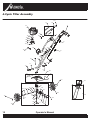
4-Cycle Tiller Assembly
T3
T46
T25
T45
T26
T40
Model 7940_4-CYCLE TILLER WITH KICKSTAND
EXPLODED VIEW
T31
T32
T36
T38
T41
T33
T35
T36
T34
T37
T38
T29
T27
T37
T28
T30
T35
T24
T23
T39
T41
T12
T11
T16
T17
22*
T20
T2
T42
T12
T13
T14
T42
T9
T9
T4
T1
Rev B, 03/20/2014
T43
T52
T53
T7
T7
T14
T15
T14
T15
T10
T18
T8
T21
T47
T50
T51
T49
T48
T44

19Contact us at www.mantis.com
Key Qty. Part No. Description
T1 1
430070 Trigger Handle Assembly, 4 Cycle Engine, Right
T2
1
430071 Handle Assembly, Left
T3
2
430082 Lower Handle W/Plug
T4
1
430084 Handle Brace Assembly
T7
2
377 Handle Clamp
T8
2
4078 M6 Jam Nut
T9
2
478 Throttle Clip
T10
1
400315 Carry Handle
T11 2
470 Bolt 1/4-20 X 3”
T12
2
400523 Knob, Two Prongs, Female
T13
2
395 Acorn Nut
T14
4
972 1/4-20 Two-Way Lock Nut
T15
2 144-2
1/4-20 X 1.125 Hex Head Cap Screw
T16
2
140 Bolt 1/4-20 X 3/8” Long
T17
1
430058 Mantis Logo Label
T18
2
4079 M6 Internal Lock Washer
T20
1
430207 Fender Guard with Label
T21
1
400911 Engine Assembly-25Cc Honda1
T22*
1
468 Drive Shaft
T23
1
466 Worm Gear Housing
T24
1
436 Gasket
T25
1
437A Gear Housing Cover
T26
4
651 #8 Self Tapping Screw
T27
1
423 Roller Bearing
T28
2
425 Worm Bearing Race
Key Qty. Part No. Description
T29
1
424 Worm Thrust Bearing
T30
1
422 Worm Shaft
T31 1
426 Worm Disk
T32 1
428 Retaining Ring
T33
1
429 Worm Gear
T34
1
431 Tine Shaft
T35
2
430 Worm Gear Thrust Washer
T36
2
432 Worm Gear Bearing
T37
2
434 Bearing Seal
T38
2
435 Bearing Seal Retainer
T39
1
438RA Tine Assembly, Right
T40
1
438LA Tine Assembly, Left
T41
2
418-1 Tine Retaining Pin
T42
2
430039 Carriage Bolt 1/4-20 X 2.25”
T43
1
430043 Ground Wire Jumper, 4 Cycle Engine
T44
1
400631 Triangle Warning Label (4 Cycly Engine)
T45
1
458 Roller Bearing
T46
1
400010 Transmission Assembly1
T47 1
400131
Clutch Drum
T48 1
400132
Bearing
T49
1
400130 Engine Flange
T50
4
400511 M6 X 12 Flange Bolt
T51 1
910502
10-32 X 3/4” Flange Bolt
T52 1
410158
Kickstand, Stand Assembly
T53 1
410113
Kickstand, Bracket And Hardware
*Also in key T46
Parts List

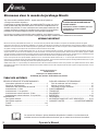
MANTIS extends this limited warranty against defects in material and workmanship for a period of ve (2) years under normal
usage for residential purposes and two (2) years under normal usage for commercial purposes, from the date of purchase by
the original purchaser.
MANTIS will repair or replace, at its option, any part or parts of the product found to be defective in material or workmanship
during the warranty period. Warranty repairs and replacements will be made without charge for parts or labor. All parts replaced
under warranty will be considered as part of the original product, and any warranty on the replaced parts will expire coincident
with the original product warranty. If you think your MANTIS TILLER is defective in material or workmanship, please contact
customer service at 800-366-6268 for the location of an authorized servicing dealer or repair center. You will be responsible for
pickup and delivery charges.
If your tiller has a [Honda] engine, this limited warranty does not cover the [Honda] engine which is warranted separately by the
engine manufacturer.
MANTIS assumes no responsibility in the event that the product was not assembled or used in compliance with any assembly,
care, safety, or operating instructions contained in the Operators Manual or accompanying the product. This limited warranty
does not cover damages or defects due to normal wear and tear, lack of reasonable and proper maintenance, failure to follow
operating instructions or operators manual, misuse, lack of proper storage or accidents. This limited warranty shall not be effective
if your Mantis tiller has been subjected to negligence or has been repaired or altered by anyone other than an authorized dealer
or authorized service center.
You must maintain your MANTIS TILLER by following the maintenance procedures described in the operators manual. Such
routine maintenance, whether performed by you or a dealer, is at your expense.
MANTIS MAKES NO EXPRESS OR IMPLIED WARRANTIES, REPRESENTATIONS OR PROMISES EXCEPT THOSE
CONTAINED HEREIN. THERE ARE NO OTHER WARRANTIES, INCLUDING WARRANTIES OF MERCHANTABILITY AND
FITNESS FOR A PARTICULAR PURPOSE. ALL WARRANTIES OTHER THAN THE EXPRESS WARRANTY SET FORTH ABOVE
ARE SPECIFICALLY DISCLAIMED. THE DURATION OF ANY IMPLIED WARRANTY, INCLUDING MERCHANTABILITY AND
FITNESS FOR A PARTICULAR PURPOSE, IS LIMITED TO THE DURATION OF THIS WRITTEN LIMITED WARRANTY. MANTIS
DISCLAIMS ALL LIABILITY FOR INDIRECT, INCIDENTAL AND/OR CONSEQUENTIAL DAMAGES IN CONNECTION WITH
THE USE OF THE MANTIS PRODUCTS COVERED BY THIS WARRANTY. SOME STATES DO NOT ALLOW LIMITATIONS ON
HOW LONG AN IMPLIED WARRANTY LASTS AND/OR DO NOT ALLOW THE EXCLUSION OR LIMITATION OF INCIDENTAL
OR CONSEQUENTIAL DAMAGES, SO THAT ABOVE LIMITATIONS AND EXCLUSIONS MAY NOT APPLY TO YOU. THIS
WARRANTY GIVES YOU SPECIFIC LEGAL RIGHTS, AND YOU MAY ALSO HAVE OTHER RIGHTS WHICH VARY FROM
STATES TO STATE.
MANTIS
1028 Street Road
Southampton, PA 18966
(215) 355-9700
©2020 Schiller Grounds Care, Inc. All Rights Reserved.
LIMITED WARRANTY
Specications, descriptions, and illustrative material in this literature are as accurate as known at the time of publication, but are
subject to change without notice.
La page est en cours de chargement...
La page est en cours de chargement...
La page est en cours de chargement...
La page est en cours de chargement...
La page est en cours de chargement...
La page est en cours de chargement...
La page est en cours de chargement...
La page est en cours de chargement...
La page est en cours de chargement...
La page est en cours de chargement...
La page est en cours de chargement...
La page est en cours de chargement...
La page est en cours de chargement...
La page est en cours de chargement...
La page est en cours de chargement...
La page est en cours de chargement...
La page est en cours de chargement...
La page est en cours de chargement...
La page est en cours de chargement...
La page est en cours de chargement...
-
 1
1
-
 2
2
-
 3
3
-
 4
4
-
 5
5
-
 6
6
-
 7
7
-
 8
8
-
 9
9
-
 10
10
-
 11
11
-
 12
12
-
 13
13
-
 14
14
-
 15
15
-
 16
16
-
 17
17
-
 18
18
-
 19
19
-
 20
20
-
 21
21
-
 22
22
-
 23
23
-
 24
24
-
 25
25
-
 26
26
-
 27
27
-
 28
28
-
 29
29
-
 30
30
-
 31
31
-
 32
32
-
 33
33
-
 34
34
-
 35
35
-
 36
36
-
 37
37
-
 38
38
-
 39
39
-
 40
40


Mantis 7940 Le manuel du propriétaire
- Catégorie
- Mini motoculteurs
- Taper
- Le manuel du propriétaire
dans d''autres langues
- English: Mantis 7940 Owner's manual
Documents connexes
-
Mantis 7940 Manuel utilisateur
-
-
-
-
-
-
-
-
-
Mantis 4222 Le manuel du propriétaire
Autres documents
-
Ryobi RY15550 Mode d'emploi
-
-
Hasbro Aliens Listing Mode d'emploi
-
Efco EF 84/14,5 K Le manuel du propriétaire
-
 Champion Power Equipment 100380 Manuel de l’opérateur
-
Greenworks G-MAX 40V Manuel utilisateur
-
Honda F502 Le manuel du propriétaire
-
 Little Wonder 2230S Le manuel du propriétaire
-
 LADIES IN RED 243 Guide d'installation
-
Troy-Bilt 290-253-081 Installation Instructions Manual


