Flotec FP4512, FP4532, FP4542, & FP4562 Deep & Shallow Well Jet Pumps Le manuel du propriétaire
- Catégorie
- Pompes à eau
- Taper
- Le manuel du propriétaire

pentair.com
INSTALLATION & OPERATION MANUAL
FP1002 (08-01-2023)
©2023 Pentair. All Rights Reserved.
DEEP AND SHALLOW WELL JET PUMPS
MODELS FP4512, FP4532, FP4542, & FP4562
6113 1109
6214 0510
6114 1109
ENGLISH: 1-16 FRENCH: 17-32 SPANISH: 33-48

FP1002 (08-01-2023)
TABLE OF CONTENTS
SAFETY INFORMATION ...................................................................................................3
INSTALLATION & OPERATION .............................................................................................5
TROUBLESHOOTING .....................................................................................................9
PUMP DISASSEMBLY ....................................................................................................10
WARRANTY ............................................................................................................ 11

3
FP1002 (08-01-2023)
SAFETY INFORMATION
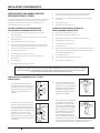
SAFETY SYMBOLS
This is the safety alert symbol. When you see this symbol on
your pump or in this manual, look for one of the following signal
words and be alert to the potential for personal injury:
warns about hazards that will cause serious
personal injury, death or major property damage if ignored.
warns about hazards that can cause serious
personal injury, death or major property damage if ignored.
warns about hazards that will or can cause minor
personal injury or property damage if ignored.
The word NOTE indicates special instructions that are important
but not related to hazards.
GENERAL SAFETY
Warranty void if product modified, drilled, painted,
or altered in any way; if used to pump hot water, or to
pump liquids other than water (such as but not limited to
chemicals, fertilizers, flammable liquids, herbicides, mud,
tar, cement, wood chips); or otherwise abused.
Carefully read and follow all safety instructions in this
manual and on pump.
Keep safety labels in good condition. Replace missing or
damaged safety labels.
Before installing or servicing your pump, BE
CERTAIN pump power source is disconnected.
All installation and electrical wiring must adhere to state
and local codes and must be complete before priming the
pump. Check with appropriate community agencies, or
contact your local electrical and pump professionals.
Pump should be installed in a dry, convenient location close
to the well with ample space for installation and servicing
the well. A dry basement, pit, or utility room is an excellent
choice when allowed by law. The pump must be securely
fastened to a solid foundation. The pump should always
be mounted in a horizontal position on a level foundation.
Failure to properly secure the pump may result in failure of
the pump or piping and damage to the surrounding area.
CALL AN ELECTRICIAN WHEN IN DOUBT. Pump motor
should be connected to a separate electrical circuit directly
from main switch. There must be a fuse box or circuit
breaker installed in this line. Plugging into existing outlets
may cause low voltage at motor, resulting in blown fuses,
tripping of motor overload, or burned-out motor. Refer to
electrical diagrams for electrical connections.
It is mandatory that a permanent ground connection be
made from the pump motor to the grounding bar at the
service panel. Do not connect pump motor to a power
supply until permanently grounded. For maximum safety,
ground the pump motor to a circuit equipped with a fault
interrupter device.
Pump must be primed! Make sure pump is full
of water before running! Failure to do so will cause damage
to mechanical seal, leakage and flooding!
NEVER run pump against closed discharge
valve! To do so can cause high temperatures, pump
damage, personal injury and property damage!
Pump may be HOT to touch. Use caution!
The following may cause severe damage to pump and/or
piping and will void warranty:
w Failure to protect pump and piping against below
freezing temperature.
w Pumping chemicals or corrosive liquids.
w Pumping gasoline or other flammable liquids. DO NOT
pump gasoline or other flammable liquids.
w Using extension cords. DO NOT use extension cords.
w Using this pump in or near a swimming pool, lake, or
pond. DO NOT use this pump in or near a swimming
pool, lake or pond.
w Running the pump dry. Follow priming instructions.
w Discharge pressure not to exceed 100 psi.
w Torque for pump bolts is 15-20 ft.-lbs.
w Use of garden hose as discharge or suction line.
w Failure to securely fastened to a solid foundation.
CALIFORNIA PROPOSITION 65 WARNING
This product and related accessories contain
chemicals known to the State of California to cause cancer,
birth defects or other reproductive harm.

4 FP1002 (08-01-2023)
INSTALLATION & OPERATION
MOTOR GROUNDING INSTRUCTIONS
Failure to ground this unit properly may result in
severe electrical shock. Do not ground to a gas supply line!
1. If the means of connection to the supply-connection box is
other than grounded metal conduit, ground the pump motor
back to the service by connecting a copper conductor, at
least the size of the circuit conductors supplying the pump
motor, to the grounding screw provided on rib underneath
wiring compartment cover. N.E.C. requires pump motor be
grounded at installation.
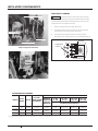
2. Voltage of power supply must match the voltage of the
pump. The 1/2 HP pump motors are factory preset to
115V. The 1 HP pump motors are preset to 230V. Both types
of motors may be wired for either 115V or 230V. If the
motor is converted to 115V, electrician should ensure that
electrical and power leads can handle the higher amps.
3. Convert Dial Type by turning dial to select 115 volts. Insert
tool in slot to turn dial. If motor is converted to 115V, an
electrician should insure electrical and power leads can
handle the higher amps.
PRIOR TO INSTALLATION
Cover well to prevent foreign matter from contaminating the
well or later damaging the pump during operation. Test well
water for purity. Chlorination may be necessary. Check local
health department for proper testing and recommendations.
FLUSHING
Hand pump new wells until clear. Pumping sand or other
sediment will seriously damage the pump and void warranty.
Periodic flushing will remove internal pump sediment buildup. To
flush:
1. Remove 1-1/2" plug from top of discharge tee, or remove
piping if no discharge tee has been installed.
2. Remove 1/4" plug from the lower front of pump.
3. Pour water into top of pump until water flowing from lower
front of pump is clear.
4. Scrape out any stubborn debris from the lower front
opening with a wire or pipe cleaner.
5. Reinstall pipes and plugs and re-prime before returning
pump to service.
6. Running the pump without discharge water
flow will cause serious damage inside the pump due to heat
buildup.
DETERMINE OPERATING DEPTH
Tie a small but heavy weight to the end of a piece of string.
Lower the weight into the well until it reaches the bottom. Take
up the slack and mark the string at ground level.
Pull the weight out of the well and measure from the bottom of
the weight to the ground level mark. This is the depth of your
well. Subtract five feet from the depth of your well. This number
should not exceed 25 feet. If it does, it will greatly hinder or
prevent the proper operation of a lawn sprinkler pump.
Determine Type of Well
1. Tie a small but heavy weight to the end of a length of string.
2. Lower into the well until the string goes slack.
3. Take up slack until string is taut and mark the string at
ground level.
4. Pull string out of well and measure length from mark to
heavy weight. This is the water depth. A shallow well pump
operates at 25 feet or less water depth. A deep well pump
operates at 70 feet or less water depth.
PIPING
All piping must be clean and free of all foreign matter to prevent
clogging. Plastic PVC pipe is shown in the illustrations, but
galvanized steel pipe may be used if desired.
All joints and connections in the well assembly must be airtight.
Even a pinhole leak will prevent the proper operation of the
pump (this is the most common problem). Use thread compound
on all threaded joints unless specified otherwise.
PUMP SETUP
Pump may be supplied attached to a shipping pallet. Inspect
pump for visible signs of damage. Remove and discard pallet
from pump before installation.
SELECT CORRECT VOLTAGE
Ensure pump circuit breaker is OFF and pump is
disconnected from power source before changing the pump
voltage.
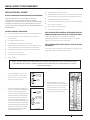
5. The selector switch to change the voltage is located
underneath the access cover on the end of the motor. To
access the switch, remove the two screws holding the
cover.
6. To change the voltage setting, turn the dial with a nut driver
or a wrench so the correct voltage shows in the cutout in
the dial. The voltage number that appears is the voltage
setting for the pump.
7. Replace the cover and secure it with the screws.

5
FP1002 (08-01-2023)
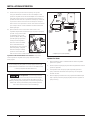
INSTALLATION & OPERATION
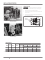
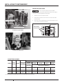
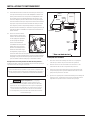
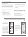
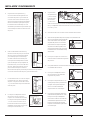
Ground Wire Connection
Pressure Switch
Voltage Change Dial
Power Supply Connections
Voltage Set to 230 Volts
Voltage Set to 115 Volts
WIRING YOUR PUMP
Ensure pump circuit breaker is OFF and pump is
disconnected from power before servicing or handling pump.
1. Remove the cover from the pressure switch.
2. Connect the bare copper ground to the ground screw in the
pressure switch.
3. Connect the power supply to the terminals marked “From
Line" in the diagram below.
Ground
Connections
To Motor
From Line
5907 1108
PUMP CAPACITIES
MODEL MOTOR
HP
VOLTS NAMEPLATE
AMPS
DISTANCE IN FEET(METERS) FROM MOTOR TO SUPPLY
BRANCH FUSE
RATING* AMP
0 - 100
(0 - 30)
101 - 200
(31 - 61)
201 - 300
(62 - 91)
301 - 400
(92 - 122)
AWG WIRE SIZE (MM²)
FP4512
FP4542 1/2 115/230 12.4/6.2 20/15 12/14 10/14 (5.5/2) 8/14(8.4/2) 6/12(14/3)
FP4532 1115/230 18.6/9.3 20/15 12/14(3/2) 18/14(8.4/2) 6/14(14/2) 6/12(14/3)
FP4562 1115/230 14.8/7.4 20/15 12/14(3/2) 8/14(8.4/2) 6/14(14/2) 6/12(14/3)
*Time delay fuse or circuit breakers are recommended in any motor circuit.

6 FP1002 (08-01-2023)
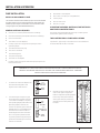
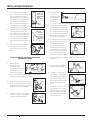
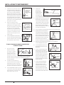
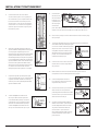
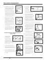
1. Thread 1-1/4" male PVC adapter into
foot valve. Hand tighten, then
tighten 1/4 turn with wrench.
2. The total length of rigid PVC pipe
and couplings to cement onto the
1-1/4" male PVC adapter is equal to
the operating depth (See Determine
Operating Depth). Cement one
section of rigid PVC pipe to the PVC
adapter which is connected to the
foot valve, then lower the whole
assembly into the well, foot valve
first. Firmly clamp the end of the
rigid PVC pipe with a pipe clamp to
prevent the assembly from sliding
further into the well.
INSTALLATION & OPERATION
PUMP INSTALLATION
INSTALL A SHALLOW WELL PUMP
The 1/2 HP FP4512 and 1 HP FP4532 pumps are recommended
for wells 25 feet or less in depth. If desired, the FP4542 and
FP4562 pumps may be converted for use with shallow wells
using an ejector kit (See REPAIR PARTS KIT).
GENERAL MATERIALS REQUIRED
One can PVC cement (read instructions carefully)
One can thread compound (read instructions carefully)
One 1-1/4" foot valve
Two male 1-1/4" PVC adapters
Enough rigid 1-1/4" PVC pipe and couplings to reach
operating depth
One well seal with vent plug
One 1-1/4" PVC elbow
One discharge tee
One pressure gauge
One male 1" PVC adapter
Enough rigid 1" PVC pipe to reach from pump to pressure
tank to service line
One female 1" PVC adapter
One 1" tank cross (for pre-charged tanks)
Two 1/4" plugs
One 1/2" drain cock
One 10" x 1" nipple
IN ADDITION TO GENERAL MATERIALS, FOR THE FP4542
AND FP4562 CONVERTIBLE ONLY
One ejector kit (See REPAIR PARTS/KITS); includes ejector,
venturi tube, gasket, bolts and plug.
TOOLS NEEDED FOR ALL PUMP INSTALLATIONS
Pipe wrench, pipe clamp, crescent wrench, slot screwdriver,
24-tooth hacksaw, knife or round file.
7082 0716
3. Cement as many couplings and
sections of rigid PVC pipe as it
takes to equal the operating depth,
then firmly clamp the assembly
with a pipe clamp to prevent the
assembly from sliding down into
the well.
FOOT
VALVE
1-1/4"
MALE PVC
ADAPTER
7125 1016
1-1/4"
MALE PVC
ADAPTER
PVC
PIPE
SECTION
FOOT
VALVE
7126 1016
REMINDER: ALL JOINTS AND CONNECTIONS MUST BE AIRTIGHT. A SINGLE PINHOLE LEAK WILL
PREVENT THE PROPER OPERATION OF THE PUMP. USE THREAD COMPOUND ON ALL THREADED
CONNECTIONS UNLESS SPECIFIED OTHERWISE.

7
FP1002 (08-01-2023)
INSTALLATION & OPERATION
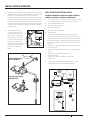
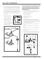
4. HOLD THE PIPE, remove pipe
clamp and slide well seal over rigid
PVC pipe and onto well casing.
Position assembly so that twelve
inches of rigid PVC pipe protrude
from well seal. Alternately turn
bolts on well seal clockwise until
rubber gaskets are tight against
well casing and rigid PVC pipe.
5. Cement 1-1/4" PVC elbow onto rigid
PVC pipe protruding from well
seal. If desired, some length may
be cut off of rigid PVC pipe before
cementing elbow. Use a round file
or knife to smooth the inside of
any rigid PVC pipe that has been
cut.
6. Thread a 1-1/4" male PVC adapter
into the front of pump. Hand
tighten, then turn 1/4 turn with
wrench.
STEPS 7–9 ARE FOR THE FP4542 AND FP4562
CONVERTIBLE PUMPS
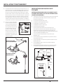
7. Open ejector kit
(FP4542 for 1/2 HP;
FP4562 for 1 HP).
Thread shorter venturi
tube into ejector on
top of the nozzle until
snug. Place gasket over venturi tube so that openings in
gasket line up with openings in ejector.
8. Slide bolts through the bolt openings
on either side of the ejector, through
the gasket and bolt ejector to front of
the pump. Tighten bolts securely.
9. Thread a 1-1/4" male PVC adapter
into front of ejector. Hand tighten,
then turn 1/4 turn with wrench.
10. Cement as many
sections and
couplings of PVC
pipe needed to
connect the PVC
elbow to the
1-1/4" male PVC adapter in the front of the pump.
11. Apply 2-3 wraps of PTFE pipe
thread sealant tape tape to the
male threads on the discharge
tee. Using pipe wrench, thread
discharge tee into top of pump.
Remove pressure gauge plug
from top of discharge tee.
12. Prime pump as described in Priming the Pump.
13. Apply 2-3 wraps of PTFE pipe
thread sealant tape tape
to plug and gauge threads.
Thread pressure gauge plug
into discharge tee and thread
pressure gauge into pressure
gauge plug. Make sure all
connections are tightly sealed.
14. Complete all electrical connections as described in Wiring
Your Pump.
15. Screw 1" male PVC adapter
into discharge tee outlet.
16. Thread 10" x 1" nipple into
pressure tank. Thread tank
cross into nipple so that the
two 1/4" holes in tank cross
face upward. Plug two outlets
on tank cross with two 1/4"
plugs.
17. Thread 1/2" boiler drain into
front of tank cross. Thread 1"
male PVC adapter into inlet
side of tank cross. Connect
household plumbing to other
side of tank cross.
APPROX.12"
OF PVC PIPE
PROTRUDING
FROM
WELL
SEAL
WELL
SEAL
7128 1016
1-1/4"
PVC
ELBOW
TOP OF
PVC PIPE
PROTRUDING
FROM WELL
SEAL
7129 1016
7158 0117
EJECTOR
BOLT
7159 0117
1-1/4"
MALE PV
C
ADAPTER
7160 0117
1-1/4" PVC PIPE
7127 1016
PRESSURE
GAUGE
PLUG
DISCHARGE
TEE
7161 0117
PRESSURE
GAUGE
7162 0117
1" MALE PVC
ADAPTER
7163 0117
TANK
CROSS
1/4" PLUGS
NIPPLE
7130 1016
1" MALE
PVC ADAPTER
1/2"
BOILER
DRAIN
7131 1016

8 FP1002 (08-01-2023)
INSTALLATION & OPERATION
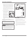
18. Cement as many sections and couplings of rigid 1" PVC pipe
needed to connect the 1" male PVC adapter in the discharge
tee to the 1" male adapter on the tank cross inlet. Set
pressure in the pre-charged pressure tank to 2 pounds less
than the cut-in pressure of the pump. If the cut in pressure
is 30 PSI, then the correct tank pre-charge is 28 PSI. If the
cut in pressure is 20 PSI, then the correct tank pre-charge
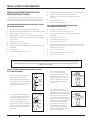
is 18 PSI. Total installation should look like the shallow well
drawing below.
19. Open a faucet or two in
the house. Start motor. If
pump is offset from well 4
feet or more, it may take a
few minutes for pressure
to build. If pressure fails to
build within five minutes:
Stop motor, remove pressure
gauge plug from discharge
tee, add more water, try
again.
WELL POINT PUMP INSTALLATION
MATERIALS NEEDED IN ADDITION TO SHALLOW WELL
GENERAL MATERIALS, FOR WELL POINTS ONLY
Enough galvanized 1-1/4" pipe and drive couplings to reach
from operating depth to one foot above ground level
One 1-1/4" galvanized elbow
One 1-1/4" galvanized nipple
One 1-1/4" check valve
One 1-1/4" male PVC adapter
One drive cap
1. Drive the well point into the ground according to the
instructions included with your well point. Use as much
galvanized pipe and as many drive couplings as it takes to
both drive the point 5-10 feet below the water table and
leave approximately one foot of pipe protruding from the
ground.
2. Thread 1-1/4" galvanized elbow onto the pipe protruding
from the ground.
3. Thread 1-1/4" galvanized nipple into the 1-1/4" galvanized
elbow.
4. Thread 1-1/4" check valve onto the 1-1/4"
galvanized nipple.
5. Thread 1-1/4" male PVC adapter into the 1-1/4"
check valve.
6. Follow STeps 6–19 in Shallow Well instructions. Total
installation should look like the drawing below.
7164 0117
6117 1109
FP4512 AND FP4532
SHALLOW WELL
FP4542 AND FP4562
CONVERTIBLE

9
FP1002 (08-01-2023)
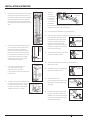
TO INSTALL THE FP4542 AND FP4562 CONVERTIBLE:
1. Thread 1-1/4" close nipple into foot
valve. Thread the other end of 1-1/4"
close nipple into bottom of ejector.
Hand tighten, then tighten 1/4 turn
with wrench.
2. The ejector has two holes in the top
of it. Thread deep well venturi tube
into larger hole on top of the nozzle
until snug. Thread 1" x 5" nipple into
smaller hole. Only hand tighten
venturi tube. Hand tighten nipple 1/4
turn with wrench.
INSTALLATION & OPERATION
INSTALL A DEEP WELL PUMP (FP4542, FP4562)
The 1 HP FP4562 is recommended for wells deeper than
25 feet but less than 70 feet. However, the 1/2 HP FP4542 pump
may also be used for depths less than 70 feet.
GENERAL MATERIALS NEEDED FOR EITHER OF THE
CONVERTIBLE PUMPS:
One can PVC cement (read instructions carefully)
One can thread compound (read instructions carefully)
Two 1" female PVC adapters
Enough rigid 1-1/4" PVC pipe and couplings to reach from
operating depth to pump (delivery pipe)
One 1-1/4" PVC elbow
One 1-1/4" male PVC adapter
One pressure regulator kit (see REPAIR PARTS KIT)
One pressure gauge
Two male 1" PVC adapters
Enough rigid 1" PVC pipe to reach from pump to pressure
tank to service line
Tank tee (for pre-charge pressure tanks)
Two 1/4" plugs
One 1/2" drain cock
IN ADDITION TO GENERAL MATERIALS FOR CONVERTIBLE
PUMPS
One 1-1/4" foot valve
One 1-1/4" close nipple
One ejector kit (see REPAIR PARTS KIT)
One 1" x 5" nipple
One 1-1/4" female adapter
One well seal
Enough rigid 1" PVC pipe and couplings to reach from
operating depth to pump (pressure pipe)
One 1" PVC elbow
Two 1-1/4" male PVC adapters
One 1" x 4" nipple
REMINDER: ALL JOINTS AND CONNECTIONS MUST BE AIRTIGHT. A SINGLE PINHOLE LEAK WILL
PREVENT THE PROPER OPERATION OF THE PUMP. USE THREAD COMPOUND ON ALL THREADED
CONNECTIONS UNLESS SPECIFIED OTHERWISE.
1-1/4"
CLOSE
NIPPLE
EJECTOR
FOOT
VALVE
7165 0117
7166 0117
3. Thread a 1-1/4" male PVC adapter
over the venturi tube and into
ejector. Thread a 1" female PVC
adapter onto the 1" x 5" nipple.
Hand tighten adapters 1/4 turn
with wrench.
4. The total length of PVC pipe and
couplings to cement onto both
1-1/4" male and 1" female PVC
adapters is equal to the operating
depth (See Determine Operating
Depth). Cement a section of PVC
pipe to each adapter, then lower
the whole assembly into the well,
foot valve first. Firmly clamp the
end of the PVC pipes with a pipe clamp to
prevent the assembly from sliding down into well.
7167 0117
7167 0117

10 FP1002 (08-01-2023)
9. Cement
as many
sections and
couplings of
rigid 1" and
1-1/4" PVC as
needed to
connect the 1" female PVC adapter and the 1-1/4" male PVC
adapter to the 1" and 1-1/4" PVC elbows.
10. Prime pump as described in Priming the Pump.
11. Open pressure regulator kit. Apply 2-3 wraps of PTFE pipe
thread sealant tape tape to the
male threads on the body of the
pressure regulator. With pipe
wrench, thread the pressure
regulator into 1" discharge at top
of pump. Thread pressure gauge
into side of pump case.
12. Thread plug into opening to right of
pressure regulator outlet.
13. Complete all electrical connections as described in
Wiring Your Pump.
14. Thread 3/4" male PVC adapter into
pressure regulator outlet.
15. Thread tank tee into
pre-charged pressure tank. Plug
two outlets on tank tee with two
1/4" plugs.
16. Thread boiler drain into front of
tank tee. Thread 3/4" male PVC
adapter into inlet side of tank tee.
Connect household plumbing to
other side of tank tee.
INSTALLATION & OPERATION
5. Cement as many couplings and sections
of rigid PVC pipe on both the pressure
and suction sides as it takes to equal the
operating depth, then firmly clamp the
assembly with a pipe clamp to prevent
the assembly from sliding down into the
well.
6. Remove pipe clamp and slide well seal
over PVC pipes and onto well casing.
DO NOT let assembly slide down
into well. Position assembly so that
twelve inches of PVC pipes protrude
from well seal. Alternately, turn bolts
on well seal clockwise until rubber
gaskets are tight against the well
casing and the PVC pipes.
7. Cut 1" pipe 2" shorter than the
1-1/4" pipe. Smooth rough
edges. Cement 1" and 1-1/4"
PVC elbows to pipes protruding from
the well seal.
8. Thread a 1-1/4" male PVC adapter into
top hole in front of pump. Thread 1"
x 4" nipple into bottom hole in front
of pump. Thread the 1" female PVC
adapter onto the 1" x 4" nipple.
7168 0117
12" OF
PVC PIPE
PROTRUD-
ING FROM
WELL
SEAL
WELL SEAL
7169 0117
1-1/4" PVC
ELBOW
1" PVC
ELBOW
1" PIPE 2"
SHORTER
THAN 1-1/4"
PIPE
7170 0117
1-1/4" MALE
PVC ADAPTER
1" x 4"
NIPPLE
1" FEMALE
PVC
ADAPTER
7171 0117
FEMALE ADAPTER
1" PVC PIPE
1-1/4" PVC PIPE
PRESSURE
REGULATOR
7172 0117
PLUG
PRESSURE
REGULATOR
OUTLET
7173 0117
3/4" MALE
PVC ADAPTER
7174 0117
1/4" PLUGS
TANK TEE
7175 0117
1/2" BOILER
DRAIN
3/4" MALE
PVC
ADAPTER
7176 0117

11
FP1002 (08-01-2023)
INSTALLATION & OPERATION
17. Cement as many sections and couplings of rigid 3/4"
PVC pipe needed to connect the 3/4" PVC adapter in the
pressure regulator to the 3/4" male adapter on the tank tee
inlet. Set pressure in the pre-charged pressure tank to 2
pounds less than the cut-in pressure of the pump. If the cut
in pressure is 30 PSI, then the correct tank pre-charge is
28 PSI. If the cut in pressure is 20 PSI, then the correct tank
pre-charge is 18 PSI. Total installation should look like the
drawing at right.
18. Open a faucet or two in the house. Start motor. Turn
regulator adjustment screw down tight. If pump is properly
primed, a high pressure will
immediately show on the
pressure gauge. With pump
operating at high pressure,
slowly unscrew regulator
stem until maximum water
flow is obtained without
dropping to 0 PSI. If pressure
falls completely, retighten
stem and readjust. Steady
pressure must not be less
than 24 PSI for the FP4542 and 32 PSI for the FP4562.
If pressure fails to build within five minutes: stop motor,
remove pressure regulator from pump, add more water,
and try again.
7177 0117
If you install your pump with a 2" single-pipe (“Packer”) jet,
please follow the installation instructions included with the
Packer jet kit (See REPAIR PARTS KIT).
Risk of explosion. If you change pressure
switch settings, set the cut-off pressure low enough to
shut off the pump. If a valve shuts off and the cut-off
setting is too high, the pump will run continuously without
water ow, causing overheating and possible explosion
which can cause serious burns and damage.
** Requires ejector (sold separately).
6120 1109 ACE
PRIMING THE PUMP
1. Open tank drain valve or a few faucets to relieve any water
pressure in system.
2. Remove pressure gauge plug from discharge tee OR remove
pressure regulator.
3. Put a garden hose into pump opening and fill pipes and
pump until water overflows from opening. This may take
several minutes.
4. After wrapping threads with PTFE pipe thread sealant tape
tape, replace pressure gauge plug OR pressure regulator in
pump housing.

12 FP1002 (08-01-2023)
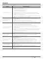
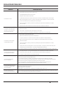
PROBLEM POSSIBLE CAUSE(S)
Pump will not prime.
Not enough water. Stop motor, remove pressure gauge bushing, and fill case and suction line
with water.
Pump wired incorrectly.
Plugged venturi tube or nozzle.
Foot valve is sitting in sand or mud, or is stuck shut, or leaks.
Low well water level. In deep wells, the ejector as well as the foot valve must be below water
level.
For the FP4542 and FP4562, the diffuser O-ring seal may be improperly positioned.
Air leaks. Check all connections for airtightness.
Pump delivers water for a
period of time, then stops
pumping.
Low well water level. Use a water-level tester while pump is operating.
Plugged venturi tube, nozzle, or impeller parts.
In deep wells, the regulator may be set incorrectly.
Pump does not deliver rated
capacity.
Plugged venturi or nozzle.
Faulty pressure gauge resulting in false readings.
In deep wells, the operating pressure may be too high.
Low well water level. Use a water-level tester while pump is operating.
For the FP4542 and FP4562, the diffuser O-ring seal may be improperly positioned.
Over-submergence of ejector. In deep wells, if ejector is more than 10 feet below pumping
level, pumping capacity is reduced.
In deep wells, the ejector may have improper size and depth setting.
Motor overheats and shuts off
(overload).
Motor voltage does not match power supply voltage. See page 3.
Improper wire size. See Wire Size Guide on page 3.
Impeller is rubbing against pump case.
Pump delivers water but will not
shut off.
Impeller is worn.
Defective pressure switch.
For the FP4542 and FP4562, the O-ring seal may be improperly positioned.
Tank precharge pressure too high. Tank precharge pressure must be two pounds less than switch
turn-on setting.
In deep wells, the water level may be going below limit of ejector. Use water-level tester
while pump is operating.
Pressure switch turns on and
off every few seconds.
Storage tank is waterlogged—add air.
Leaky foot valve.
Too much tank pressure.
Bladder/diaphragm in pre-charged tank may be ruptured.
Motor fails or does not operate
properly.
If within Warranty, return pump/motor unit to place of purchase (with proof of purchase)
for exchange.
TROUBLESHOOTING

13
FP1002 (08-01-2023)
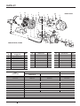
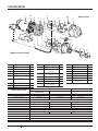
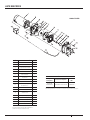
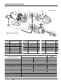
PARTS LIST
11A
34
6
8
9
10
11
12
13
914
11
10
6 8
15
16
10
17
7
5
2
6125 1109
18
12
7
19
20
21
Models FP4542, FP4562
Model FP4512
KEY
NO.
PART
DESCRIPTION QTY
1Motor 1
1A Motor Flange Screw 4
2Slinger 1
3Seal Plate 1
4Shaft Seal 1
5 Seal Plate O-Ring 1
6Impeller 1
7Venturi 1
PART
DESCRIPTION
CONVERTIBLE (DEEP WELL) PUMPS SHALLOW WELL PUMPS
FP4542 1/2 HP FP4562 1 HP FP4512 1/2 HP
Motor J218-1652 J218-1653 J218-1652
Pump Case 18623D020 18623D020 24357D020
Seal Plate 24452C000 24452C021 24452C000
20/40 Pressure Switch U217-1218
Overhaul Kit FPPK50 FPPK100 FPPK50
Ejector Kit* FP4542 FP4562 –
Pressure Regulator Kit*†FPAPR FPAPR –
Packer Jet Kit* FP4840 FP4840 –
Pressure switch tubing kit FPASFK-P2
Seal and Gasket Kit RPK-35 RPK-35 RPK-35
Kits Include:
Overhaul Kit (1/2 HP) Key Nos 4, 5, 6, 7, 8, 12
Overhaul Kit (1 HP) Key Nos 4, 5, 6, 7, 8, 12
Ejector Kit†Key Nos 7, 12, 18, 19, 20(2), 21(2)
KEY
NO.
PART
DESCRIPTION QTY
8Diffuser 1
9 Diffuser Plate Screw 3
10 1/4” NPT x 1/4” Barb Elbow 2
11 Pump Body 1
12 Nozzle 1
13 Pressure Regulator 1
14 Diffuser Plate O-Ring 1
KEY
NO.
PART
DESCRIPTION QTY
15 Tubing 1
16 Base 1
17 Pressure switch 1
18 Ejector Gasket 1
19 Ejector Body 1
20 Washer 2
21 Ejector Capscrew 2

14 FP1002 (08-01-2023)
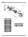
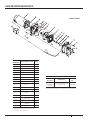
PARTS LIST
KEY
NO.
PART
DESCRIPTION QTY
1Motor 1
2Slinger 1
3Seal Plate 1
4Motor Flange Screw* 4
5Shaft Seal 1
6 Seal Plate Gasket* 1
7Impeller* 1
8Diffuser* 1
9Diffuser Plate 1
10 Diffuser Plate Screw*†3
11 Venturi 1
12 Nozzle 1
13 Diffuser Plate O-Ring 1
14 Pump Body 1
15 Pump Housing Screw†4
16 Pipe Plug 2
17 Tubing 1
18 Pressure switch 1
REPAIR PARTS KIT**
Part
Description Kit Includes FP4532
1 HP
Overhaul Kit Key Nos. 5, 6, 7, 8, 11, 12 FPPKS100
*Included in Overhaul Kit
†Purchase at local hardware store.
**Purchase separately—kit is not included with pump.
Model FP4532

15
FP1002 (08-01-2023)
WARRANTY
LIMITED WARRANTY
This Limited Warranty is effective July 11, 2019 and replaces all undated warranties and warranties dated before July 11, 2019.
Pentair Flotec* warrants to the original consumer purchaser (“Purchaser” or “You”) that its products are free from defects in material and
workmanship for a period of twelve (12) months from the date of the original consumer purchase. If, within twelve (12) months from the original
consumer purchase, any such product shall prove to be defective, it shall be repaired or replaced at Pentair Flotec’s option, subject to the terms and
conditions set forth herein. Note that this limited warranty applies to manufacturing defects only and not to ordinary wear and tear. All mechanical
devices need periodic parts and service to perform well. This limited warranty does not cover repair when normal use has exhausted the life of a part
or the equipment.
The original purchase receipt and product warranty information label are required to determine warranty eligibility. Eligibility is based on purchase
date of original product – not the date of replacement under warranty. The warranty is limited to repair or replacement of original purchased product
only, not replacement product (i.e. one warranty replacement allowed per purchase). Purchaser pays all removal, installation, labor, shipping, and
incidental charges.
Claims made under this warranty shall be made by returning the product (except sewage pumps, see below) to the retail outlet where it was
purchased immediately after the discovery of any alleged defect. Pentair Flotec will subsequently take corrective action as promptly as reasonably
possible. No requests for service will be accepted if received more than 30 days after the warranty expires.
Warranty is not transferable and does not apply to products used in commercial/rental applications.
For parts or troubleshooting assistance, DO NOT return product to your retail store - contact Pentair Flotec Customer Service at 1-800-365-6832.
SEWAGE PUMPS
DO NOT return a sewage pump (that has been installed) to your retail store. Sewage pumps that have seen service and been removed carry a
contamination hazard with them.
If your sewage pump has failed:
Wear rubber gloves when handling the pump;
For warranty purposes, return the pump’s cord tag and original receipt of purchase to the retail store;
Dispose of the pump according to local disposal ordinances.
Contact Pentair Flotec Customer Service at 1-800-365-6832.
EXCEPTIONS TO THE TWELVE (12) MONTH LIMITED WARRANTY
GENERAL TERMS AND CONDITIONS; LIMITATION OF REMEDIES
You must pay all labor and shipping charges necessary to replace product covered by this warranty. This warranty does not apply to the following: (1)
acts of God; (2) products which, in the sole judgment of Pentair Flotec, have been subject to negligence, abuse, accident, misapplication, tampering,
or alteration; (3) failures due to improper installation, operation, maintenance or storage; (4) atypical or unapproved application, use or service;
(5)failures caused by corrosion, rust or other foreign materials in the system, or operation at pressures in excess of recommended maximums.
This warranty sets forth the sole obligation of Pentair Flotec, and purchaser’s exclusive remedy for defective products.
PENTAIR FLOTEC SHALL NOT BE LIABLE FOR ANY CONSEQUENTIAL, INCIDENTAL, OR CONTINGENT DAMAGES WHATSOEVER.
THE FOREGOING WARRANTIES ARE EXCLUSIVE AND IN LIEU OF ALL OTHER EXPRESS AND IMPLIED WARRANTIES, INCLUDING BUT NOT LIMITED
TO THE IMPLIED WARRANTIES OF MERCHANTABILITY AND FITNESS FOR A PARTICULAR PURPOSE. THE FOREGOING WARRANTIES SHALL NOT
EXTEND BEYOND THE DURATION PROVIDEDHEREIN.
Some states do not allow the exclusion or limitation of incidental or consequential damages or limitations on how long an implied warranty lasts, so
the above limitations or exclusions may not apply to You. This warranty gives You specific legal rights and You may also have other rights which vary
from state to state.
(3/10/2022)
PRODUCT WARRANTY PERIOD
Parts2O* (Parts & Accessories), FP0F360AC, FP0FDC 90 days
FP0S1775A, FP0S4100X, FPPSS3000, FPCC5030, FPCI3350, FPCI5050, FPDC30 2 Years
FPSC1725X, FPSE3601A, FPSC3350A, FPZT7300, FPZT7350, FPZT7450, FPZT7550 2 Years
FP7100/FP7400 Series Pressure Tanks, E3305TLT, E3375TLT, E5005TLTT, E50TLT, E50VLT, E75STVT, E75VLT,
FPSE9000, FPSE9050 5 Years

All indicated Pentair trademarks and logos are property of Pentair. Third party registered and unregistered trademarks and logos are the property of their respective owners. Because we are
continuously improving our products and services, Pentair reserves the right to change specications without prior notice. Pentair is an equal opportunity employer.
©2023 Pentair. All Rights Reserved. FP1002 (08-01-2023)
293 Wright St
Delavan, WI 53115
Ph: 800.365.6832
Fx: 800.426.9446
490 Pinebush Rd., Unit 4
Cambridge, Ontario
Canada N1T 0A5
Ph: 800.363.7867
PENTAIR.COM

pentair.com
GUIDE DE L’UTILISATEUR
FP1002 (08-01-2023)
© Pentair, 2023. Tous droits réservés.
POMPES À JET POUR PUITS PROFONDS
ET PEU PROFONDS
MODÈLESFP4512, FP4532, FP542 ET FP4562
6113 1109
6214 0510
6114 1109

18 FP1002 (08-01-2023)
TABLE DES MATIÈRES
CONSIGNES DE SÉCURITÉ ...............................................................................................19
INSTALLATION ET FONCTIONNEMENT ....................................................................................20
DÉPANNAGE ...........................................................................................................28
DÉMONTAGE DE LA POMPE ...............................................................................................29
GARANTIE .............................................................................................................. 31

19
FP1002 (08-01-2023)
INFORMATION RELATIVE À LA SÉCURITÉ
SYMBOLES DE SÉCURITÉ
Ceci est le symbole d’alerte de sécurité. Si vous voyez ce
symbole sur votre pompe ou dans ce guide, cherchez l’un des
mots d’avertissement ci-dessous et soyez attentif aux risques de
blessures corporelles.
signale un danger qui provoquera des blessures
graves, la mort ou des dommages matériels importants, s’il est ignoré.
signale un danger qui peut provoquer des blessures
corporelles graves, la mort ou des dommages matériels importants,
s’il est ignoré.
ATTENTION
signale un danger qui provoquera ou peut provoquer
des blessures corporelles légères ou des dommages matériels, s’il
est ignoré.
Le mot REMARQUE indique des consignes spéciales importantes,
mais non liées aux dangers.
SÉCURITÉ GÉNÉRALE
La garantie est invalidée si le produit est modifié, percé, peint
ou altéré de quelque manière; s’il est utilisé pour pomper de
l’eau chaude ou d’autres liquides que de l’eau (y compris, mais
sans s’y limiter des produits chimiques, des engrais, des liquides
inflammables, des herbicides, de la boue, du goudron, du
ciment, des copeaux de bois); ou a subi tout autre préjudice.
Lisez attentivement et suivez toutes les instructions de sécurité
de ce manuel et sur la pompe.
Conservez les étiquettes de sécurité en bon état. Remplacez-les
si elles sont manquantes ou endommagées.
Avant l’installation ou l’entretien de votre pompe,
ASSUREZ-VOUS que la source d’alimentation de la pompe est
débranchée.
Tous les câblages électriques et d’installation doivent être
conformes aux codes fédéraux et locaux et doivent être installés
avant l’amorçage de la pompe. Vérifiez auprès des organismes
compétents ou communiquez avec les professionnels dans le
domaine de l’électricité et des pompes de votre région.
La pompe doit être installée dans un endroit sec et pratique
à proximité du puits, avec un espace suffisamment grand
pour permettre l’installation ainsi que l’entretien du puits. Un
sous-sol sec, une fosse ou un local d’entretien est un excellent
choix, si la loi l’autorise. La pompe doit être fixée de manière
sécuritaire à une fondation solide. La pompe doit toujours être
montée en position horizontale sur une fondation plane. Une
mauvaise fixation de la pompe peut causer une défaillance de
cette dernière ou des tuyaux en plus d’endommager la zone
environnante.
EN CAS DE DOUTE, COMMUNIQUEZ AVEC UN ÉLECTRICIEN.
Le moteur de la pompe doit être connecté à un circuit électrique
distinct, directement depuis l’interrupteur principal. Une boîte
à fusibles ou un disjoncteur doit être installé sur cette ligne.
Le branchement dans les prises existantes peut causer une
faible tension du moteur, qui peut brûler les fusibles, déclencher
la surcharge du moteur ou griller ce dernier. Reportez-vous
aux schémas électriques pour connaître les raccordements
électriques.
Une connexion permanente à la terre réalisée à partir de la
pompe jusqu’à la barre de mise à la terre du panneau de service
est obligatoire. Ne raccordez pas le moteur de la pompe à
une source d’alimentation avant qu’il ne soit mis à la terre de
manière permanente. Pour plus de sécurité, mettez le moteur
de la pompe à la terre en le connectant à un circuit équipé d’un
dispositif d’interrupteur de défaillance.
ATTENTION
La pompe doit être amorcée! Assurez-vous de
remplir la pompe avant de l’activer! Si ce n’est pas le cas, des
dommages au joint mécanique, une fuite et une inondation
peuvent se produire!
Ne faites JAMAIS fonctionner la pompe
lorsque le robinet de refoulement est fermé. Cela peut causer
une surchauffe, des dommages à la pompe, des blessures
corporelles et des dommages matériels.
La pompe peut être CHAUDE au toucher. Prenez garde!
Les actions suivantes peuvent causer des dommages
importants à la pompe et/ou à la tuyauterie, et annuler
la garantie:
w Ne pas protéger la pompe et la tuyauterie contre les
températures sous le point de congélation.
w Pomper des produits chimiques ou des liquides corrosifs.
w Pomper de l’essence ou d’autres liquides inflammables. Ne
pompez PAS d’essence ou d’autres liquides inflammables.
w Utiliser des rallonges. N’utilisez PAS de rallonges.
w Utiliser cette pompe dans ou près d’une piscine, d’un lac ou
d’un étang. N’utilisez PAS cette pompe dans ou près d’une
piscine, d’un lac ou d’un étang.
w Faire fonctionner la pompe à sec. Respectez les instructions
d’amorçage.
w La pression d’évacuation ne doit pas dépasser 100psi.
w Le couple de serrage des boulons de la pompe est de
15à20pi-lb.
w Utiliser un tuyau d’arrosage en tant que conduite
d’évacuation ou d’aspiration.
w Omettre de fixer de façon sécuritaire à une fondation solide.
AVERTISSEMENT CONCERNANT LA PROPOSITION65 DE
LA CALIFORNIE
Ce produit et les accessoires connexes
contiennent un produit chimique considéré par l’État de la
Californie comme pouvant causer le cancer, des anomalies
congénitales ou d’autres problèmes liés au système de
reproduction.

20 FP1002 (08-01-2023)
INSTALLATION ET FONCTIONNEMENT
INSTRUCTIONS RELATIVES À LA MISE À LA TERRE DU MOTEUR
Une mauvaise mise à la terre de cet appareil peut causer
une décharge électrique grave. Ne faites pas la mise à la terre sur une
conduite d’alimentation en gaz.
1.
Si la boîte de jonction de l’alimentation n’est pas reliée à un conduit
métallique mis à la terre, mettez le moteur de la pompe à la terre
en connectant un conducteur en cuivre, dont la taille est au moins
équivalente à celle des conducteurs du circuit alimentant le moteur
de la pompe, à la vis de mise à la terre fournie sur la nervure se
trouvant sous le couvercle du compartiment de câblage. Le Code
national de l’électricité (NEC) exige que le moteur de la pompe soit
mis à la terre au moment de l’installation.
2. La tension de l’alimentation doit correspondre à la tension de la
pompe. Les moteurs de pompe 1/2HP sont préréglés en usine à 115V.
Les moteurs de pompe 1HP sont préréglés en usine à 230V. Les
deux moteurs peuvent être câblés pour 115V ou 230V. Si le moteur
est converti à 115V, un électricien doit s’assurer que les faisceaux
électriques et de puissance peuvent supporter une intensité plus
élevée.
3. Modifiez l’intensité en tournant le cadran pour sélectionner 115V.
Insérez un outil dans la fente pour tourner le cadran. Si le moteur est
converti à 115V, un électricien doit s’assurer que les fils électriques et
d’alimentation peuvent prendre en charge une intensité plus élevée.
AVANT L’INSTALLATION
Couvrez le puits pour éviter que des matières étrangères ne contaminent
le puits ou endommagent la pompe pendant son fonctionnement.
Analysez la pureté de l’eau du puits. Une chloration pourrait être
nécessaire. Consultez les autorités sanitaires de votre région
pour connaître les méthodes d’analyse appropriées et obtenir des
recommandations.
RINÇAGE
Pompez à la main un nouveau puits jusqu’à ce que l’eau soit transparente.
Le pompage de sable ou d’autre sédiment peut endommager
sérieusement la pompe et annuler la garantie. Un rinçage périodique
permettra de retirer l’accumulation de sédiments à l’intérieur de la
pompe. Pour rincer:
1. Retirez le bouchon de1 1/2 po du haut du raccord d’évacuation en
T ou retirez la tuyauterie si aucun raccord d’évacuation en T n’est
installé.
2. Retirez le bouchon de 1/4 po de la partie inférieure avant de la
pompe.
3. Versez de l’eau dans le haut de la pompe jusqu’à ce que l’eau
s’écoulant de la partie inférieure avant soit transparente.
4. Retirez tout débris tenace de l’ouverture inférieure avant à l’aide
d’une brosse ou d’un cure-pipe.
5. Réinstallez les tuyaux et les bouchons et procédez à un réamorçage
avant de remettre la pompe en service.
6.
ATTENTION
L’utilisation de la pompe sans qu’il y ait écoulement
d’eau d’évacuation peut causer des dommages importants à
l’intérieur de la pompe en raison de l’accumulation de chaleur.
DÉTERMINER LA PROFONDEUR DE FONCTIONNEMENT
Accrochez un poids petit et lourd à l’extrémité d’une ficelle. Faites
descendre le poids dans le puits jusqu’à ce qu’il atteigne le fond.
Remontez la partie lâche de la ficelle et faites une marque sur la ficelle au
niveau du sol.
Retirez le poids du puits et mesurez la longueur du fond jusqu’à la marque
de niveau du sol. Cela représente la profondeur du puits. Soustrayez cinq
pieds à la profondeur du puits. Ce chiffre ne doit pas dépasser 25pieds.
Une profondeur qui dépasse cette mesure nuira au fonctionnement de la
pompe d’un tourniquet d’arrosage.
Déterminer le type de puits
1. Accrochez un poids petit et lourd à l’extrémité d’une ficelle.
2. Faites descendre le poids dans le puits jusqu’à ce que la ficelle ne
soit plus tendue.
3. Remontez la partie lâche de la ficelle et faites une marque sur la
ficelle au niveau du sol.
4. Tirez la ficelle hors du puits et mesurez la longueur de la marque
jusqu’au poids. Cela représente la profondeur d’eau. Une pompe
de puits peu profond fonctionne jusqu’à une profondeur d’eau
de 25pieds. Une pompe de puits profond fonctionne jusqu’à une
profondeur d’eau de 70pieds.
TUYAUTERIE
L’ensemble de la tuyauterie doit être propre et exempte de tout corps
étranger pour éviter les obstructions. Un tuyau en plastique (PVC) est
montré sur les illustrations, mais un tuyau en acier galvanisé peut être
utilisé si souhaité.
Tous les joints et raccords de l’ensemble du puits doivent être étanches
à l’air. Même une petite fuite empêchera le bon fonctionnement de la
pompe (il s’agit du problème le plus courant). Utilisez une graisse pour
filetage sur tous les raccords filetés, à moins d’indication contraire.
INSTALLATION DE LA POMPE
La pompe pourrait être fixée sur une palette d’expédition. Assurez-vous
que la pompe ne présente aucun dommage visible. Retirez la pompe de la
palette d’expédition et jetez celle-ci avant de procéder à l’installation.
SÉLECTION DE LA BONNE TENSION
Assurez-vous que le disjoncteur est HORS TENSION et
que la pompe est débranchée avant de modifier le réglage de la tension
de la pompe.
5. Le sélecteur de tension pour modifier le réglage de la tension se
trouve sous le couvercle à l’extrémité du moteur. Pour accéder
au sélecteur, retirez les deux vis qui maintiennent le couvercle en
place.
6. Pour modifier le réglage de la tension, tournez le cadran à l’aide
d’un tournevis à douille ou d’une clé jusqu’à ce que la bonne tension
s’affiche dans la découpe du cadran. Le chiffre indiquant la tension
correspond au réglage de la tension de la pompe.
7. Remettez le couvercle et fixez-le avec les vis.
La page est en cours de chargement...
La page est en cours de chargement...
La page est en cours de chargement...
La page est en cours de chargement...
La page est en cours de chargement...
La page est en cours de chargement...
La page est en cours de chargement...
La page est en cours de chargement...
La page est en cours de chargement...
La page est en cours de chargement...
La page est en cours de chargement...
La page est en cours de chargement...
La page est en cours de chargement...
La page est en cours de chargement...
La page est en cours de chargement...
La page est en cours de chargement...
La page est en cours de chargement...
La page est en cours de chargement...
La page est en cours de chargement...
La page est en cours de chargement...
La page est en cours de chargement...
La page est en cours de chargement...
La page est en cours de chargement...
La page est en cours de chargement...
La page est en cours de chargement...
La page est en cours de chargement...
La page est en cours de chargement...
La page est en cours de chargement...
-
 1
1
-
 2
2
-
 3
3
-
 4
4
-
 5
5
-
 6
6
-
 7
7
-
 8
8
-
 9
9
-
 10
10
-
 11
11
-
 12
12
-
 13
13
-
 14
14
-
 15
15
-
 16
16
-
 17
17
-
 18
18
-
 19
19
-
 20
20
-
 21
21
-
 22
22
-
 23
23
-
 24
24
-
 25
25
-
 26
26
-
 27
27
-
 28
28
-
 29
29
-
 30
30
-
 31
31
-
 32
32
-
 33
33
-
 34
34
-
 35
35
-
 36
36
-
 37
37
-
 38
38
-
 39
39
-
 40
40
-
 41
41
-
 42
42
-
 43
43
-
 44
44
-
 45
45
-
 46
46
-
 47
47
-
 48
48


Flotec FP4512, FP4532, FP4542, & FP4562 Deep & Shallow Well Jet Pumps Le manuel du propriétaire
- Catégorie
- Pompes à eau
- Taper
- Le manuel du propriétaire
dans d''autres langues
Documents connexes
Autres documents
-
Pentair FP5112 Manuel utilisateur
-
Simer 2207C Le manuel du propriétaire
-
Pentair FP4200 Series Le manuel du propriétaire
-
MYERS HJ, HR Series Jet Pumps Le manuel du propriétaire
-
red lion RL-SWJ Series Le manuel du propriétaire
-
AquaPRO 60013 Mode d'emploi
-
 Utilitech LPT-52 Manuel utilisateur
-
Wayne SWS5085FX WYN2 Mode d'emploi
-
Pentair 3PL, 5PL, 7PL, 10PL, 10PLS11C, 15PLS11C Le manuel du propriétaire
-
 Pompco PJC Le manuel du propriétaire

