
MultiConnect
®
xDot
TM
MTXDOT Developer Guide


CONTENTS
MultiConnect
®
xDot
TM
MTXDOT Developer Guide 3
Contents
Chapter 1 – Product Overview ................................................................................................................................. 7
Overview ....................................................................................................................................................................... 7
What's New in Firmware Version 3.1 ........................................................................................................................... 7
xDot Bootloader.......................................................................................................................................................... 7
Power Optimization .................................................................................................................................................... 7
Other Enhancements .................................................................................................................................................. 7
Documentation Overview ............................................................................................................................................. 7
Related Documentation.............................................................................................................................................. 8
mbed Documentation ................................................................................................................................................... 8
Programming the xDot Microcontroller ..................................................................................................................... 8
General mBed Links .................................................................................................................................................... 8
xDot Platform ............................................................................................................................................................. 9
EUI and Networking ...................................................................................................................................................... 9
Product Build Options ................................................................................................................................................. 10
Chapter 2 – Getting Started ................................................................................................................................... 11
Getting Started with the xDot Developer Kit.............................................................................................................. 11
COM Port Enumeration by Operating System ............................................................................................................ 11
Linux.......................................................................................................................................................................... 11
Windows ................................................................................................................................................................... 11
Mac ........................................................................................................................................................................... 12
Updating Firmware Using the xDot Bootloader ......................................................................................................... 12
Chapter 3 – Mechanical Drawings with Pinouts ..................................................................................................... 14
xDot............................................................................................................................................................................. 14
Chapter 4 – Specifications and Pin Information...................................................................................................... 16
MTXDOT Specifications............................................................................................................................................... 16
Mapping Data Rate to Spreading Factor/Bandwidth................................................................................................ 18
LoRa Transmission Output Power............................................................................................................................... 19
868 Models ............................................................................................................................................................... 19
915 Models ............................................................................................................................................................... 19
Battery Draw Down..................................................................................................................................................... 20
Electrical and Timing Characteristics ........................................................................................................................ 20
Measuring the Power Draw ...................................................................................................................................... 21
Pin Information .......................................................................................................................................................... 22
Pin Information ......................................................................................................................................................... 22
Pull-Up/Down............................................................................................................................................................ 24
LoRa ........................................................................................................................................................................... 24
Secure Element ......................................................................................................................................................... 24

CONTENTS
4 MultiConnect
®
xDot
TM
MTXDOT Developer Guide
Crystals/Oscillator ..................................................................................................................................................... 24
Sleep Wake and Deep Sleep Wake Pins ................................................................................................................... 25
InterruptIn Limitations.............................................................................................................................................. 25
xDot Pinout Design Notes ........................................................................................................................................... 26
Serial Pinout Notes.................................................................................................................................................... 26
Serial Settings.............................................................................................................................................................. 26
LoRa ............................................................................................................................................................................ 26
Throughput Rates...................................................................................................................................................... 26
Range ........................................................................................................................................................................ 26
Resetting the xDot ...................................................................................................................................................... 28
Chapter 5 – Antennas ............................................................................................................................................ 29
Antenna System ......................................................................................................................................................... 29
U.FL and Trace Antenna Options ............................................................................................................................... 29
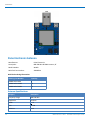
Pulse Electronics Antenna........................................................................................................................................... 30
Antenna Specifications ............................................................................................................................................. 30
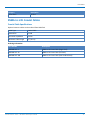
RSMA-to-U.FL Coaxial Cables ..................................................................................................................................... 31
Coaxial Cable Specifications ..................................................................................................................................... 31
Ethertronics Chip Antenna.......................................................................................................................................... 32
Antenna Specifications ............................................................................................................................................. 32
Stackup Information.................................................................................................................................................... 32
Developer Board Layer Stackup................................................................................................................................ 32
Stackup Table............................................................................................................................................................ 33
Impedance ................................................................................................................................................................ 33
Chip Antenna Design Guidelines................................................................................................................................. 35
Antenna Pad Layout.................................................................................................................................................. 36
PCB Layout ................................................................................................................................................................ 36
Antenna Matching Network........................................................................................................................................ 37
915 ............................................................................................................................................................................ 37
868 ............................................................................................................................................................................ 38
OEM Integration ......................................................................................................................................................... 38
FCC & IC Information to Consumers ......................................................................................................................... 38
FCC Grant Notes........................................................................................................................................................ 38
Host Labeling............................................................................................................................................................... 39
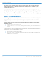
Chapter 6 – Safety Information .............................................................................................................................. 40
Handling Precautions .................................................................................................................................................. 40
Radio Frequency (RF) Safety ....................................................................................................................................... 40
Sécurité relative aux appareils à radiofréquence (RF).............................................................................................. 40
Interference with Pacemakers and Other Medical Devices ...................................................................................... 41
Potential interference............................................................................................................................................... 41
Precautions for pacemaker wearers ........................................................................................................................ 41
Device Maintenance ................................................................................................................................................... 41

CONTENTS
MultiConnect
®
xDot
TM
MTXDOT Developer Guide 5
User Responsibility...................................................................................................................................................... 42
Chapter 7 – Regulatory Information....................................................................................................................... 43
EMC, Safety, and Radio Equipment Directive (RED) Compliance .............................................................................. 43
47 CFR Part 15 Regulation Class B Devices ................................................................................................................. 43
FCC Interference Notice ............................................................................................................................................. 43
FCC Notice................................................................................................................................................................... 43
Industry Canada Class B Notice................................................................................................................................... 44
Chapter 8 – Environmental Notices........................................................................................................................ 45
Waste Electrical and Electronic Equipment Statement .............................................................................................. 45
WEEE Directive.......................................................................................................................................................... 45
Instructions for Disposal of WEEE by Users in the European Union ........................................................................ 45
REACH Statement ....................................................................................................................................................... 45
Registration of Substances........................................................................................................................................ 45
Substances of Very High Concern (SVHC) ................................................................................................................ 45
Restriction of the Use of Hazardous Substances (RoHS) ............................................................................................ 46
Information on HS/TS Substances According to Chinese Standards ......................................................................... 47
Information on HS/TS Substances According to Chinese Standards (in Chinese) ...................................................... 48
Chapter 9 – Labels.................................................................................................................................................. 49
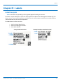
Label Examples............................................................................................................................................................ 49
Chapter 10 – Developer Kit Overview .................................................................................................................... 50
xDot Developer Kit ..................................................................................................................................................... 50
Developer Kit Package Contents............................................................................................................................... 50
Firmware Updates..................................................................................................................................................... 50
Programming Devices in Production ........................................................................................................................ 50
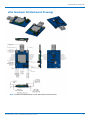
xDot Developer Kit Mechanical Drawings................................................................................................................... 51
Micro Developer Board LEDs ...................................................................................................................................... 52
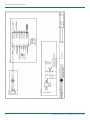
Chapter 11 – Developer Board Schematics............................................................................................................. 53
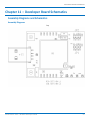
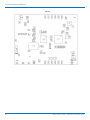
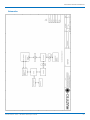
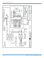
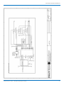
Assembly Diagrams and Schematics........................................................................................................................... 53
Assembly Diagrams................................................................................................................................................... 53
Schematics ................................................................................................................................................................ 55
Chapter 12 – Design Considerations....................................................................................................................... 59
Noise Suppression Design........................................................................................................................................... 59
PC Board Layout Guideline ......................................................................................................................................... 59
Electromagnetic Interference .................................................................................................................................... 59
Electrostatic Discharge Control................................................................................................................................... 60
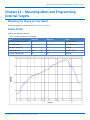
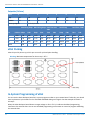
Chapter 13 – Mounting xDots and Programming External Targets ......................................................................... 61
Mounting the Device on Your Board .......................................................................................................................... 61
Solder Profile............................................................................................................................................................... 61
Setpoints (Celsius)..................................................................................................................................................... 62
xDot Packing ............................................................................................................................................................... 62

CONTENTS
6 MultiConnect
®
xDot
TM
MTXDOT Developer Guide
In-System Programming of xDot................................................................................................................................. 62
Schematic Example ................................................................................................................................................... 63
Recommended Programming Hardware for Production.......................................................................................... 63
JTAG/SWD Connector .............................................................................................................................................. 64
Chapter 14 – Appendix A Release Note Archive ..................................................................................................... 65
What's New in Firmware Version 3.0 ......................................................................................................................... 65
LoRaWAN 1.0.2 Support ........................................................................................................................................... 65
Listen Before Talk ..................................................................................................................................................... 65
Separate Channel Plans ............................................................................................................................................ 65
Index...................................................................................................................................................................... 66

PRODUCT OVERVIEW
MultiConnect
®
xDot
TM
MTXDOT Developer Guide 7
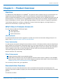
Chapter 1 – Product Overview
Overview
The MultiConnect xDot (MTXDOT) is a LoRaWAN
TM
, low-power RF device, capable of two way communication over
long distances, deep into buildings, or within noisy environments
*
using the unlicensed ISM bands in North
America, Europe and worldwide. The xDot is a compact surface-mount device with an mbed enabled processor and
enhanced security. The xDot features an integrated ARM
®
Cortex
®
-M3 processor and mbed
TM
compatible software
library for developers to control, monitor and bring edge intelligence to their Internet of Things (IoT) applications.
*
Actual distance depends on conditions, configuration, antennas, desired throughput, and usage frequency. In
dense urban environments, a typical range is 1-2 miles.
What's New in Firmware Version 3.1
The new release includes the following changes:
xDot Bootloader
Power Optimization
Other Enhancements
xDot Bootloader
The xDot bootloader allows firmware upgrades via ymodem over either the command or debug serial ports. For
details, refer to Updating Firmware Using the xDot Bootloader.
Power Optimization
To reduce power consumption during Class A transactions, Version 3.1 firmware includes a new auto sleep feature.
When enabled, the microcontroller automatically goes into a stop sleep mode after an uplink transmit ends and in
between two receive windows. In the stop sleep mode, RAM and register contents are retained, but all peripheral
clocks are gated, so timers will not count during these intervals. Refer to the microcontroller datasheet for
information regarding microcontroller sleep mode states.
New AT Command: +AS - Auto Sleep
Other Enhancements
Adaptive Data Rate (ADR) is now enabled by default.
Public Network command, +PN, has been updated to include an MTS network in addition to the LoRaWAN
public or private network options. This includes changes to parameter values. Refer to the +PN command in
S000643 DOT Series AT Command Reference Guide for details.
For an archive of release notes, go to Appendix A.
Documentation Overview
This manual is one part of xDot documentation. Refer to the Related Documentation and mbed sections for
additional information needed to program your xDot and integrate your application with the MultiConnect Conduit
gateway.
This document includes:


PRODUCT OVERVIEW
10 MultiConnect
®
xDot
TM
MTXDOT Developer Guide
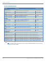
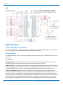
Product Build Options
Product Description Package Quantity
North America
MTXDOT-NA1-A00 915 MHz LoRa Module UFL/TRC (NAM) 1, 100, or 1000
MTXDOT-NA1-A01 915 MHz LoRa Module TRC (NAM) 1, 100, or 1000
EMEA
MTXDOT-EU1-IN1-A00 868 MHz LoRa Module UFL/TRC (EU) 1 or 100
MTXDOT-EU1-IN1-A01 868 MHz LoRa Module TRC (EU) 100
Australia
MTXDOT-AU1-A00 AU915 MHz LoRa Module UFL/TRC (AU) 1 or 100
MTXDOT-AU1-A01 AU915 MHz LoRa Module TRC (AU) 100
AS923
MTXDOT-AS1-A00 AS923 MHz LoRa Module UFL/TRC (APAC) 1 or 100
Japan
MTXDOT-JP1-A00 AS923 MHz LoRa Module w/LBT UFL/TRC (JP) 1 or 100
Korea
MTXDOT-KR1-A00 KR920 MHz LoRa Module w/LBT UFL/TRC (KR) 1 or 100
Developer Kits
MTMDK-XDOT-NA1-A00 MultiConnect xDot Micro Developer Kit - Includes a 915 MHz xDot
MTMDK-XDOT-EU1-IN1-A00 MultiConnect xDot Micro Developer Kit - Includes a 868 MHz xDot
MTMDK-XDOT-AU1-A00 MultiConnect xDot Micro Developer Kit - Includes a AU915 MHz xDot
MTMDK-XDOT-AS1-A00 MultiConnect xDot Micro Developer Kit - Includes a AS923 MHz xDot
MTMDK-XDOT-JP1-A00 MultiConnect xDot Micro Developer Kit - Includes a AS923 w/LTB MHz xDot
MTMDK-XDOT-KR1-A00 MultiConnect xDot Micro Developer Kit - Includes a KR920 w/LBT MHz xDot
Note:
The complete product code may end in .Rx. For example, MTXDOT-NA1-A00.Rx, where R is revision
and x is the revision number.

GETTING STARTED
MultiConnect
®
xDot
TM
MTXDOT Developer Guide 11
Chapter 2 – Getting Started
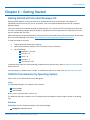
Getting Started with the xDot Developer Kit
Getting started depends on what you want to do. By default, xDot ships with firmware that supports AT
Commands that use the serial I/O. For AT Commands, refer to the separate MultiConnect Dots AT Command
Reference Guide.
Two serial interfaces are available through the USB interface, one is used to send AT commands to the xDot and
the other is for debug messages. Refer to Chapter 4, Specifications and Pin Information for information on which
pins are available out of the box.
Before starting your project development, make sure you have the latest firmware for the Developer Kit and xDot.
Go to the xDot mbed page for firmware. https://developer.mbed.org/platforms/MTS-xDot-L151CC/
To send commands to the xDot:
1. Plug the developer board into a USB port.
2. Open communications software, such as TeraTerm, Putty, or Minicom.
3. Set the following:
Baud rate = 115,200
Data bits = 8
Parity = N
Stop bits = 1
Flow control = Off
To develop using mbed, the xDot mbed page includes libraries and test cases. Refer to mbed Documentation for
details and links.
For help setting up a MultiConnect
®
Conduit
™
to send data to and from an xDot, refer to Related Documentation .
COM Port Enumeration by Operating System
xDots create an AT Commands port and a debug port.
Linux
The following COM ports are created on Linux systems:
/dev/ttyACMx
/dev/ttyACMy
Where x and y may be 0 and 1, 3 and 4, etc.
The COM port with lower number is the AT command port and COM port with the higher number is the debug
port.
Windows
On Windows systems, COM ports appear in the Device Manager:
Debug Port: mbed Serial Port


GETTING STARTED
MultiConnect
®
xDot
TM
MTXDOT Developer Guide 13
}
For the application, create a file with the following content. Name it mbed_app.json and place it in the root
directory.
{
"target_overrides": {
"XDOT_L151CC": {
"target.bootloader_img": "bootloader_location/bootloader.bin"
}
}
}

MECHANICAL DRAWINGS WITH PINOUTS
14 MultiConnect
®
xDot
TM
MTXDOT Developer Guide
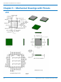
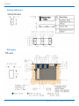
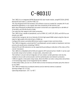
Chapter 3 – Mechanical Drawings with Pinouts
xDot

MECHANICAL DRAWINGS WITH PINOUTS
MultiConnect
®
xDot
TM
MTXDOT Developer Guide 15
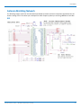
Note: The xDot development board uses a land pattern that matches the xDot land pattern in the previous
image. All pads are 0.028 inches square except the large one, which is 0.098 inches x 0.028 inches.

SPECIFICATIONS AND PIN INFORMATION
16 MultiConnect
®
xDot
TM
MTXDOT Developer Guide
Chapter 4 – Specifications and Pin Information
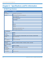
MTXDOT Specifications
Category Description
General
Compatibility LoRaWAN 1.0 specifications
Interfaces Note that pin functions are multiplexed.
Up to 19 digital I/O
Up to 10 analog inputs
2 DAC outputs
I2C
SPI
Wake pin
Reset pin
Full UART
mbed/simple UART (RX & TX only)
mbed programming interface
CPU Performance
CPU 32 MHz
Max Clock 32 MHz
Flash Memory 256 KB, with xDot library 136 KB available; with AT firmware, 56 KB available
EEPROM 8 KB, available 6 KB
SRAM 32 KB
Backup Register 128 byte, available 88
Radio Frequency
ISM Bands 863 MHz - 868 MHz, 902 MHz - 928 MHz, 915 MHz - 935 MHz
Physical Description
Weight 0.0001 oz. (0.003g)
Dimensions Refer to Mechanical Drawings for Dimensions.
RF Connectors
-UFL Models U.FL
-Trace Models Trace Connection

SPECIFICATIONS AND PIN INFORMATION
MultiConnect
®
xDot
TM
MTXDOT Developer Guide 17
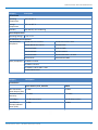
Category Description
Environment
Operating
Temperature
-40° C to +85° C
Storage
Temperature
-40° C to +85° C
Humidity 20%-90% RH, non-condensing
Power Requirements
Operating Voltage 2.4 to 3.57 V
Certifications and Compliance
EMC and Radio
Compliance
EN 300 220-2 V2.4.1:2012 EN 300 220-2 V2.4.1:2012
EN 301 489-03 V1.6.1:2013 ICES-003:2012
FCC 15.247:2015 CISPR 22:2008
FCC 15.109:2015 AS/NZS CISPR 22
FCC 15.107:2015 AS/NZS 4268:2012 + a1:2013
RSS 247:2015 Standard 2014 MPE
Safety Compliance UL 60950-1 2nd ED
cUL 60950-1 2nd ED
IEC 60950-1 2nd ED AM1 + AM2
AS/NZS 60950.1:2015
Category Description
Transmission
North America, Asia, Australia EMEA
Max Transmitter
Power Output (TPO)
19 dBm 14 dBm
Maximum Receive
Sensitivity
-137 dBm -137 dBm
Link Budget
1
147 dB Point-to-Point 147 dB Point-to-Point
Max Effective
Isotropic Radiated
Power (EiRP)
22 dBm 10 dBm

SPECIFICATIONS AND PIN INFORMATION
18 MultiConnect
®
xDot
TM
MTXDOT Developer Guide
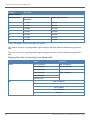
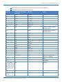
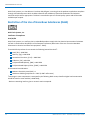
Category Description
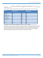
Receive Sensitivity
Spreading Factor North America, Asia, Australia Typical
Sensitivity
2
EMEA Typical Sensitivity
3
6 -111 dBm -121 dBm
7 -116 dBm -124 dBm
8 -119 dBm -127 dBm
9 -122 dBm -130 dBm
10 -125 dBm -133 dBm
11 -127 dBm -135 dBm
12 -129 dBm -137 dBm
1
Greater link budget is possible with higher gain antenna.
2
RFS_L500: RF sensitivity, Long-Range Mode, highest LNA gain, LNA boost, 500 kHz bandwidth using split Rx/Tx
path.
3
RFS_L125: RF sensitivity, Long-Range Mode, highest LNA gain, LNA boost, 125 kHz bandwidth using split Rx/Tx
path.
Mapping Data Rate to Spreading Factor/Bandwidth
Uplink Downlink
US/AU DR0: SF10BW125 DR8: SF12BW500
DR1: SF9BW125 DR9: SF11BW500
DR2: SF8BW125 ...
DR3: SF7BW125 DR13: SF7BW500
DR4: SF8BW500
DR5-DR7: RFU
EU DR0: SF12BW125
...
DR5: SF7BW15
DR6: SF7BW250
DR7: FSK

SPECIFICATIONS AND PIN INFORMATION
MultiConnect
®
xDot
TM
MTXDOT Developer Guide 19
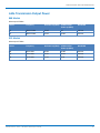
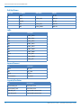
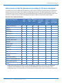
LoRa Transmission Output Power
868 Models
Max output 25 dBm
Power Frequency On Power-up (dBm) 18 Hours After
Power-up (dBm)
Bandwidth
27 869.525 MHz 24.18 25 125 kHz
27 869.525 MHz 24.18 24.83 250 kHz
915 Models
Max output 27 dBm
Power Frequency On Power-up (dBm) 18 Hours After
Power-up (dBm)
Bandwidth
26 923.3 MHz 26.58 25.88 500 kHz
26 925.1 MHz 26.76 26.34 500 kHz
26 927.5 MHz 27.22 26.8 500 kHz

SPECIFICATIONS AND PIN INFORMATION
20 MultiConnect
®
xDot
TM
MTXDOT Developer Guide
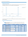
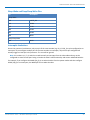
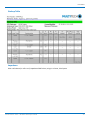
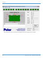
Battery Draw Down
xDot battery life depends on many variables, including transmit power, data rate, sleep usage, and duty cycle. The
following figure represents the current consumption in one possible application.
Use the current consumption values from the following Electrical Characteristics table when calculating average
power consumption.
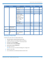
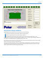
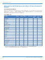
Electrical and Timing Characteristics
Note:
All measurements taken at VDD = 3.3 V and 25 degrees Celsius ambient temperature unless
otherwise specified.
Refer to the ST Micro STM32L151CC datasheet for more detailed processor IO characteristics.
Signal Description Conditions Min Typical Max Units
VCC Operating Voltage 2.4 3.3 3.57 V
Vin Low IO input low level -- -- 0.3V * VDD V
Vin High IO input high level 0.45 * VDD + 0.6 V
Vout Low IO output low level Pin current = 8mA - 0.4 V
Vout High IO output high level 2.7V < VDD < 3.6V VDD - 0.4 V
Vout Low IO output low level Pin current = 20mA -- 1.3 V
Vout High IO output high level 2.7V < VDD < 3.6V VDD - 1.3 V
La page est en cours de chargement...
La page est en cours de chargement...
La page est en cours de chargement...
La page est en cours de chargement...
La page est en cours de chargement...
La page est en cours de chargement...
La page est en cours de chargement...
La page est en cours de chargement...
La page est en cours de chargement...
La page est en cours de chargement...
La page est en cours de chargement...
La page est en cours de chargement...
La page est en cours de chargement...
La page est en cours de chargement...
La page est en cours de chargement...
La page est en cours de chargement...
La page est en cours de chargement...
La page est en cours de chargement...
La page est en cours de chargement...
La page est en cours de chargement...
La page est en cours de chargement...
La page est en cours de chargement...
La page est en cours de chargement...
La page est en cours de chargement...
La page est en cours de chargement...
La page est en cours de chargement...
La page est en cours de chargement...
La page est en cours de chargement...
La page est en cours de chargement...
La page est en cours de chargement...
La page est en cours de chargement...
La page est en cours de chargement...
La page est en cours de chargement...
La page est en cours de chargement...
La page est en cours de chargement...
La page est en cours de chargement...
La page est en cours de chargement...
La page est en cours de chargement...
La page est en cours de chargement...
La page est en cours de chargement...
La page est en cours de chargement...
La page est en cours de chargement...
La page est en cours de chargement...
La page est en cours de chargement...
La page est en cours de chargement...
La page est en cours de chargement...
La page est en cours de chargement...
-
 1
1
-
 2
2
-
 3
3
-
 4
4
-
 5
5
-
 6
6
-
 7
7
-
 8
8
-
 9
9
-
 10
10
-
 11
11
-
 12
12
-
 13
13
-
 14
14
-
 15
15
-
 16
16
-
 17
17
-
 18
18
-
 19
19
-
 20
20
-
 21
21
-
 22
22
-
 23
23
-
 24
24
-
 25
25
-
 26
26
-
 27
27
-
 28
28
-
 29
29
-
 30
30
-
 31
31
-
 32
32
-
 33
33
-
 34
34
-
 35
35
-
 36
36
-
 37
37
-
 38
38
-
 39
39
-
 40
40
-
 41
41
-
 42
42
-
 43
43
-
 44
44
-
 45
45
-
 46
46
-
 47
47
-
 48
48
-
 49
49
-
 50
50
-
 51
51
-
 52
52
-
 53
53
-
 54
54
-
 55
55
-
 56
56
-
 57
57
-
 58
58
-
 59
59
-
 60
60
-
 61
61
-
 62
62
-
 63
63
-
 64
64
-
 65
65
-
 66
66
-
 67
67


Multitech MultiConnect xDot MTXDOT-NA1-A00 Developer's Manual
- Taper
- Developer's Manual
dans d''autres langues
Documents connexes
-
Multitech MTXDOT-NA1-A00-100 Mode d'emploi
-
Multitech MTCAP-915-001A Mode d'emploi
-
-
-
-
-
-
-
Multitech MTQ-MNA1-B01-SP Mode d'emploi
Autres documents
-
Multi-Tech MultiConnect xDot MTXDOT-868 Series Developer's Manual
-
RAK 172 WisDuo LPWAN Module Manuel utilisateur
-
Zenner OD2 Manuel utilisateur
-
 KingSmith C-8031U Integrated WiFi and Bluetooth BLE Dual Mode Module Manuel utilisateur
-
RAK 200 WisDuo LoRa Module Manuel utilisateur
-
Godox GX-SEKONIC-A Wireless Module Manuel utilisateur
-
Powercast TX91503 Manuel utilisateur
-
COREKINECT NATLRA1 Manuel utilisateur
-
ARI UNI42 Mode d'emploi
-
 ST Engineering MIU1USLA Meter Interface Unit Manuel utilisateur

