Lorex LNZ32P4 Serie Manuel utilisateur
- Catégorie
- Des caméras de sécurité
- Taper
- Manuel utilisateur
Ce manuel convient également à

Instruction Manual
LNZ32P4 SERIES 4x IP PTZ
DOME CAMERA
LNZ32P4_SERIES_MANUAL_TRILINGUAL_R4

Thank you for purchasing this product. Lorex is committed to providing our customers with a high quality,
reliable security solution.
This manual refers to the following model:
LNZ32P4
For the latest online manual, downloads and product updates, and to learn about our complete line of
accessory products, please visit our website at:
www.lorextechnology.com
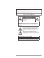
WARNING
RISK OF ELECTRIC SHOCK
DO NOT OPEN
WARNING: TO REDUCE THE RISK OF ELECTRIC SHOCK DO NOT REMOVE
COVER. NO USER SERVICEABLE PARTS INSIDE.
REFER SERVICING TO QUALIFIED SERVICE PERSONNEL.
The lightning flash with arrowhead symbol, within an equilateral
triangle, is intended to alert the user to the presence of uninsulated
"dangerous voltage" within the product’s enclosure that may be of
sufficient magnitude to constitute a risk of electric shock.
The exclamation point within an equilateral triangle is intended to
alert the user to the presence of important operating and
maintenance (servicing) instructions in the literature accompanying
the appliance.
WARNING: TO PREVENT FIRE OR SHOCK HAZARD, DO NOT EXPOSE THIS UNIT
TO RAIN OR MOISTURE.
CAUTION: TO PREVENT ELECTRIC SHOCK, MATCH WIDE BLADE OF THE PLUG
TO THE WIDE SLOTAND FULLY INSERT.
#LX400075; r.41474/44665; en-US
iv

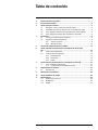
Table of contents
1 Safety Instructions ..............................................................................1
2 Getting Started....................................................................................2
3 Connecting the Camera........................................................................3
3.1 OPTION 1: Connecting Cameras to an NVR .....................................3
3.2 OPTION 2: Connecting Cameras to the Local Area Network
(LAN) .......................................................................................3
3.3 Adding the PTZ Camera to the LNR / NR Series NVRs........................5
3.4 Adding the PTZ camera to the LNK Series NVRs ...............................6
4 Installation .........................................................................................8
4.1 Installation Tips and Warnings .......................................................8
4.2 Installation (Indoor/Outdoor)..........................................................8
4.2.1 Wall Mounting .................................................................8
4.2.2 Ceiling Mounting ............................................................ 13
5 Controlling the PTZ Camera with an NVR.............................................. 14
6 Controlling the PTZ camera with LNR / NR Series NVRs ......................... 15
6.1 Controlling the PTZ Camera ........................................................ 15
6.2 Advanced PTZ Controls ............................................................. 16
6.2.1 Presets ........................................................................ 17
6.2.2 Tours........................................................................... 17
6.2.3 Pattern......................................................................... 18
7 Controlling the PTZ camera with LNK Series NVRs ................................ 20
7.1 Controlling the PTZ camera......................................................... 20
7.1.1 Setting PTZ Presets........................................................ 21
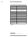
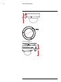
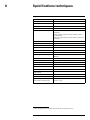
8 Technical Specifications..................................................................... 23
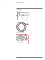
8.1 Dimensions ............................................................................. 23
9 Troubleshooting ................................................................................ 25
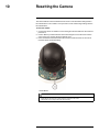
10 Resetting the Camera ........................................................................ 26
11 Notices............................................................................................. 27
11.1 FCC/IC Notice.......................................................................... 27
11.2 Modification............................................................................. 27
11.3 ROHS .................................................................................... 27
#LX400075; r.41474/44665; en-US
v

Safety Instructions
1
• Read this guide carefully and keep it for future reference.
• Follow all instructions for safe use of the product and handle with care.
• Use the camera within given temperature, humidity, and voltage levels noted in the
Technical Specifications.
• Camera is rated for outdoor use and is weatherproof when properly installed. Camera
is not intended for submersion in water. Installation under a sheltered environment is
recommended.
• Do not disassemble the camera.
• Do not point the camera directly towards the sun or a source of intense light.
• Use only the supplied regulated power supply. Use of a non-regulated, non-conforming
power supply can damage this product and voids the warranty.
• Make sure to install the camera in a location that can support the camera weight.
• Make sure there are no live electrical cables in the area where you plan to mount the
camera.
• Periodic cleaning may be required. Use a damp cloth only. Do not use anything other
than water to clean the dome cover, as chemicals such as acetone can permanently
damage the plastic.
#LX400075; r.41474/44665; en-US
1

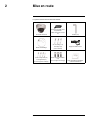
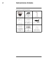
Getting Started
2
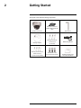
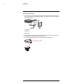
The system comes with the following components:
IP PTZ Dome Camera
100ft (30.5m) CAT5e UL
Compliant Ethernet Extension
Cable
Allen Key (x2)
Mounting Template
Mounting Screws (x3)
& Anchors (x3)
(For camera)
Wall Mounting Bracket
Mounting Screws ST4 (x4)
& Anchors S6 (x4)
(For wall mounting bracket)
Hex Bolt M4x10 (x3)
(For wall mounting bracket)
Installation Diagram Guide
and Instructional Manual
#LX400075; r.41474/44665; en-US
2

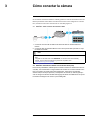
Connecting the Camera
3
It is recommended to connect the camera to your NVR and test the PTZ controls before
permanent installation. For instructions on how to setup PTZ controls, see 5 Controlling
the PTZ Camera with an NVR, page 14.
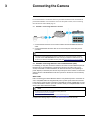
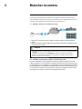
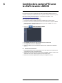
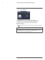
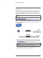
3.1 OPTION 1: Connecting Cameras to an NVR
1. Connect the PoE connector on the camera cable to the included Ethernet extension
cable.
2. Connect the Ethernet extension cable to one of the PoE ports on the back panel of
your NVR.
NOTE
• You can use a single CAT5e Ethernet cable up to 300ft (91m) to connect the camera to your NVR.
• Compatible with the LNR / NR / LNK Series NVRs, excluding the LNR200 and LNR300 Series. For
the most up-to-date list of compatible recorders, please visit www.lorextechnology.com/compatibility.
3.2 OPTION 2: Connecting Cameras to the Local Area Network (LAN)
For flexibility, you may also connect the camera to the same Local Area Network (LAN) as
the NVR. This is accomplished by connecting the camera to the same router (not in-
cluded) as the NVR. For these installations, an external PoE switch (sold separately) or
power adapter (not included) must be used to provide power to the camera. You must also
add the camera on the NVR before it will show a picture on the monitor or be recorded by
the NVR.
What is PoE?
PoE is a technology that allows Ethernet cables to carry electrical power to connected de-
vices. Compatible NVRs use integrated PoE ports to provide power and PTZ commands
to the camera, as well as video connection to the NVR over a single CAT5E cable. In order
to use PoE with this IP camera, you must connect it directly to a compatible NVR or a PoE
switch on the same network as the NVR.
NOTE
• For the most up-to-date list of compatible recorders, please visit
www.lorextechnology.com/compatibility
• PoE switches are available for purchase on www.lorextechnology.com.
Complete the following steps to connect the camera to the NVR over the LAN.
#LX400075; r.41474/44665; en-US
3

Connecting the Camera
3
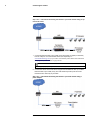
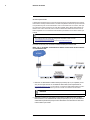
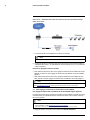
Step 1 of 2 — OPTION A: Connecting the camera to your local network using an op-
tional PoE switch:
1. Connect an Ethernet cable of up to 300ft (91m) rated CAT5e or higher (not included)
from the LAN port on an external PoE switch (sold separately on
www.lorextechnology.com) to your router. Connect the power cable to the PoE switch
and plug into a power outlet or surge protector.
NOTE
Terminology may vary depending on the model of PoE switch you have.
2. Connect the camera to the PoE switch using the included Ethernet cable (or a CAT5e
Ethernet cable of up to 300ft (91m)). The PoE switch will provide power and video
transmission the same way as your NVR.
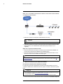
Step 1 of 2 — OPTION B: Connecting the camera to your local network using a
power adapter:
#LX400075; r.41474/44665; en-US
4

Connecting the Camera
3
1. Connect the camera to a power adapter (not included).
NOTE
For power requirement specification, see 8 Technical Specifications.
2. Connect the camera to a router in the same network as your NVR using the included
Ethernet cable (or an Ethernet cable of up to 300ft (91m) rated CAT5e or higher).
Step 2 of 2: Add the camera to your NVR:
• For instructions on adding the PTZ camera to the LNR / NR Series NVRs , see 3.3 Add-
ing the PTZ Camera to the LNR / NR Series NVRs, page 5
• For instructions on adding the PTZ camera to the LNK Series NVRs, see 3.4 Adding
the PTZ camera to the LNK Series NVRs, page 6
NOTE
For instructions on how to locate the serial and model number of your recorder, visit www.lorextechnology.
com and search for “Where is the Serial and Model Number located”.
3.3 Adding the PTZ Camera to the LNR / NR Series NVRs
To add the PTZ camera to the LNR / NR Series NVRs:
The following instructions are based on the LNR400 Series NVR. See your NVR’s instruc-
tion manual for instructions on controlling the PTZ camera with your system.
NOTE
• Not compatible with LNR200 / LNR300 Series NVRs. For the latest list of compatible recorders, see
www.lorextechnology.com/compatibility.
• You must have at least one empty channel before attempting to add the camera to the NVR.
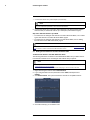
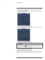
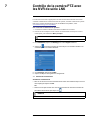
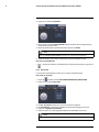
1. Right-click during live view and select Device Search.
2. Log in using the admin account (default user name: admin; default password:
000000).
3. Click Device Search. The system searches the network for compatible cameras.
4. Check the camera(s) you would like to add.
#LX400075; r.41474/44665; en-US
5

Connecting the Camera
3
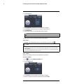
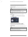
5. Click Add. The Status indicator turns green to show the camera is successfully
connected.
6. Click OK to save changes.
NOTE
You can also add a camera to a specific channel by hovering the mouse over an empty channel in split-
screen view and clicking
. Click Device Search and double-click the camera you would like to add.
Right click to exit.
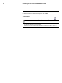
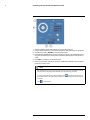
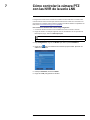
3.4 Adding the PTZ camera to the LNK Series NVRs
To add the PTZ camera to the LNK Series NVRs:
The following instructions are based on the LNK7000 Series NVR. See your NVR’s in-
struction manual for instructions on controlling the PTZ camera with your system.
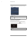
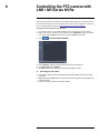
1. From live view, hover over a blank channel. Click
in the center of the channel to
add the PTZ camera from the LAN. A Quick Add menu opens.
NOTE
If prompted, enter the system user name (default: admin) and your password.
#LX400075; r.41474/44665; en-US
6

Connecting the Camera
3
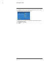
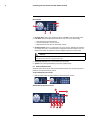
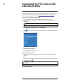
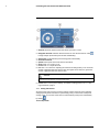
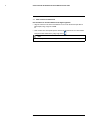
2. Click Search. The NVR scans the network for compatible cameras. A list of compati-
ble cameras appear on the left-side of the screen.
3. Click the camera you would like to add. The selected camera’s attributes appear on
the right-side of the screen.
4. Under Protocol, select ONVIF.
5. Click Add.
#LX400075; r.41474/44665; en-US
7

Installation
4
4.1 Installation Tips and Warnings
• Camera is rated for outdoor use. It is recommended to install the camera in a sheltered
area, such as under the eaves on a roof.
• Use the included wall mounting bracket for wall installation. Otherwise, the camera im-
age will be sideways. You can also refer to the included installation diagram guide for
wall mounting instructions.
• Camera is capable of seeing in low light conditions (0.1 Lux), but it cannot see in total
darkness.
NOTE
It is recommended to install the camera where there is some ambient light (for example, street lighting
or starlight, moonlight, etc.) or leave some lighting on in the area where the camera is installed.
• Mount the camera in a location that can support the camera weight.
• Mount the camera where the lens is away from direct and intense sunlight.
• Plan your cable wiring so that it does not interfere with power lines or telephone lines.
• Ensure you adhere to local building codes.
• Ensure that the camera wiring is not exposed or easily cut.
• Mount the camera in an area that is visible but out of reach.
NOTE
This camera is suitable for ceiling mounting. Wall mounting requires included wall mount.
4.2 Installation (Indoor/Outdoor)
The camera includes all necessary components for ceiling mounting and wall mounting.
For full instructions on each type of mounting, see 4.2.1 Wall Mounting or 4.2.2 Ceiling
Mounting.
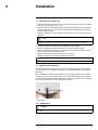
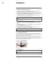
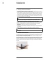
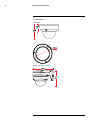
Before installing the camera, decide whether to run the cables through the wall / ceiling
(drilling required) or along the wall / ceiling. If you run the cables along the wall / ceiling,
you must run the cable through the cable notch on the dome camera base. This will keep
the dome camera base flush to the ceiling when mounted.
1. Cable Notch
4.2.1 Wall Mounting
CAUTION
Make sure to install in a location that can support the combined weight of the wall mounting bracket and
the camera.
#LX400075; r.41474/44665; en-US
8

Installation4
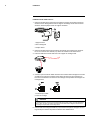
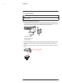
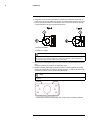
To wall mount the camera:
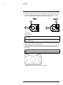
1. Use the Allen key (S3.0) included with the wall mounting bracket kit to loosen the hex
lock on the bottom of the wall mounting bracket. Once loose, remove the back plate of
the mounting bracket.
1. Wall Mount
2. Hex Lock
3. Back Plate
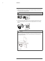
2. Use the Allen key included with the camera mounting kit to loosen the dome camera
cover screws (x3). Remove the dome camera cover.
3. Insert the camera cable through the hole in the wall mounting bracket.
#LX400075; r.41474/44665; en-US
9

Installation4
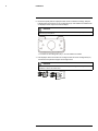
4. Ensure that the cable notch on the dome camera base is aligned with the cable notch
on the wall mounting bracket. Align the 3 mounting holes on the dome camera base
with the 3 corresponding mounting holes on the wall mounting bracket.
1: Cable Notch
2: Mounting Holes
NOTE
The wall mount you received may have more or less mounting holes than the one depicted in this
guide. The mounting holes (3x) on the dome camera base will align with the corresponding mounting
holes on the wall mount.
5. Use the Hex Bolt M4x10 (x3) screws included with the wall mounting bracket kit to se-
cure the position of the dome camera base.
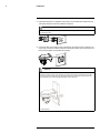
6. Holding the flat side of the back plate against the mounting surface, mark holes for the
mounting screws ST4 (x4) and the camera cable. Remove the back plate and drill
where marked.
NOTE
You do not need to mark holes for the camera cable if you plan to run it along the wall / ceiling.
1: Mounting screw ST4 (x4) holes, 2: Camera cable hole
#LX400075; r.41474/44665; en-US
10

Installation4
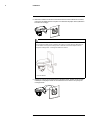
7. Attach the back plate to the mounting surface using the mounting screws ST4 (x4) in-
cluded with the wall mounting bracket kit.
NOTE
Use the drywall anchors included with the wall mounting bracket kit if installing on a drywall surface.
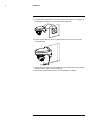
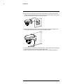
8. Connect the camera cable as shown in the 3 Connecting the Camera section, then
feed the cables through the cable hole in the back plate (attached to the mounting
surface).
CAUTION
If you run the cables along the mounting surface, you must run the cable through the side notch
on the wall mounting bracket. The camera cable will hang alongside the wall mounting bracket —
see image below for reference:
1. Side Notch
#LX400075; r.41474/44665; en-US
11

Installation4
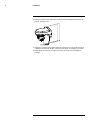
9. Lower the wall mounting bracket onto the back plate. Ensure that the 2 metal flaps on
the back plate lock into the 2 grooves in the wall mounting plate.
10. Use the included Allen key (S3.0) to tighten the hex lock on the bottom of the wall
mounting bracket.
11. Replace the dome camera cover and tighten the dome camera cover screws using the
Allen key included with the camera mounting kit.
12. Remove the vinyl film from the dome cover once installation is complete.
#LX400075; r.41474/44665; en-US
12

Installation4
4.2.2 Ceiling Mounting
To ceiling mount the camera:
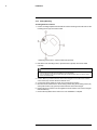
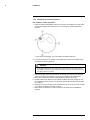
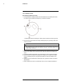
1. Use the mounting template included with the camera mounting kit to mark holes for the
mounting screws (x3) and camera cable.
1. Mounting screw holes; 2. Camera cable hole (Optional)
2. Drill holes for the mounting screws, drywall anchors (optional) and camera cable
(optional).
NOTE
• Use the included drywall anchors if installing on a drywall surface.
• If you are planning on running the cables along the mounting surface, there is no need to drill a
hole for the camera cable.
3. Use the Allen key included with the camera mounting kit to loosen the dome camera
cover screws (x3). Remove the dome camera cover.
4. Connect the camera cables as shown in 3 Connecting the Camera.
5. Mount the dome camera base to the mounting surface using the mounting screws (x3)
and drywall anchors (x3) (optional) included with the camera mounting kit.
6. Replace the dome camera cover and tighten the dome camera cover screws using the
included Allen key.
7. Remove the vinyl film from the dome cover once installation is complete.
#LX400075; r.41474/44665; en-US
13

Controlling the PTZ Camera with
an NVR
5
The camera can accept PTZ commands directly through the Ethernet cable. There is no
need to run special wiring to control the movement of the PTZ camera.
LNZ32P4 camera is compatible with LNR / NR / LNK Series NVRs, excluding the LNR200
and LNR300 Series NVRs.
• For instructions on controlling the PTZ camera with the LNR / NR Series NVRs, see 6
Controlling the PTZ camera with LNR / NR Series NVRs, page 15
• For instructions on controlling the PTZ camera with the LNK Series NVRs, see 7 Con-
trolling the PTZ camera with LNK Series NVRs, page 20
#LX400075; r.41474/44665; en-US
14

Controlling the PTZ camera with
LNR / NR Series NVRs
6
The following instructions are based on the LNR400 Series NVR. See your NVR’s instruc-
tion manual for instructions on controlling the PTZ camera with your system. For the latest
list of compatible NVRs, please visit www.lorextechnology.com/compatibility.
To connect the PTZ camera to the system:
1. Connect the camera to your NVR as detailed in 3 Connecting the Camera, page 3.
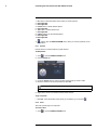
2. Right-click on the live view of the PTZ camera and click Main Menu. Enter the system
user name (default: admin) and password (default: 000000) if prompted.
3. Click
>SETTING>PAN/TILT/ZOOM.
4. Under Channel, select the channel your PTZ camera is connected to.
5. Under PTZ Type, select Remote.
6. Click OK. You can now control your PTZ camera using the system.
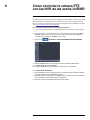
6.1 Controlling the PTZ Camera
1. In Live View, double-click the channel that has the PTZ camera connected to open in
full-screen.
2. Right-click and click PTZ. Enter the system user name and password if prompted. The
PTZ menu opens.
3. Use the on-screen controls to control the camera.
#LX400075; r.41474/44665; en-US
15

Controlling the PTZ camera with LNR / NR Series NVRs
6
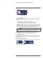
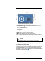
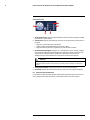
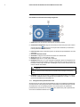
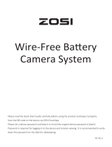
PTZ Controls
1. Direction keys: Click to pan and tilt the camera. Click SIT to stop the current action.
2. PTZ Trace: Click to activate mouse PTZ Trace mode. You can do the following:
• Click and drag to move the camera.
• Use the scroll wheel to zoom in and out.
• Right-click to exit and return to normal PTZ controls.
3. Zoom/Focus/Iris: Click +/- to adjust the zoom, focus, and iris. Adjusting the camera’s
iris settings allow you to control the amount of light that enters the camera’s lens. The
higher the iris value, the greater the amount of light that enters the camera’s lens.
CAUTION
Adjust the camera’s iris settings to match the environment where the camera is installed. Too much
light exposure might result in a very bright camera image.
4. Advanced controls: Click to open advanced PTZ controls.
5. Speed: Enter a PTZ speed between 1 (slowest) and 8 (fastest).
6.2 Advanced PTZ Controls
Advanced PTZ controls can be used to save camera positions and cycle through various
positions, and automate camera actions.
To open advanced PTZ controls:
• Click the arrow in the PTZ control window to open advanced controls.
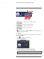
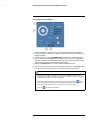
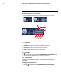
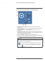
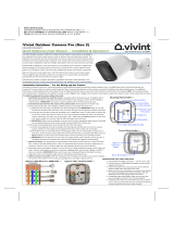
Advanced PTZ controls overview:
#LX400075; r.41474/44665; en-US
16

Controlling the PTZ camera with LNR / NR Series NVRs
6
1. No.: Click to select the number of the action you want to perform.
2. Not supported.
3. Not supported.
4. Preset: Click to call the selected preset.
5. Not supported.
6. Tour: Click to run the selected tour.
7. Not supported.
8. Pattern: Click to run the selected pattern.
9. Not supported.
10. Not supported.
11.
: Click to open the PAN/TILT/ZOOM menu, where you can set up Presets, Tours,
and Patterns.
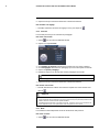
6.2.1 Presets
Presets will save a camera position for quick retrieval.
To add presets:
1. Click
to open the PAN/TILT/ZOOM menu.
2. Click the Preset tab.
3. Under the Preset text box, enter the number of the preset you want to create.
4. Move the camera to the desired position and click Set.
NOTE
Click Del Preset to delete a preset.
5. Right-click to return to the advanced PTZ controls window.
To go to a preset:
• Under No., select the number of the preset you would like to go to and click
.
6.2.2 Tours
Tours will cycle through a set of presets.
To create a tour:
1. Click
to open the PAN/TILT/ZOOM menu.
#LX400075; r.41474/44665; en-US
17
La page est en cours de chargement...
La page est en cours de chargement...
La page est en cours de chargement...
La page est en cours de chargement...
La page est en cours de chargement...
La page est en cours de chargement...
La page est en cours de chargement...
La page est en cours de chargement...
La page est en cours de chargement...
La page est en cours de chargement...
La page est en cours de chargement...
La page est en cours de chargement...
La page est en cours de chargement...
La page est en cours de chargement...
La page est en cours de chargement...
La page est en cours de chargement...
La page est en cours de chargement...
La page est en cours de chargement...
La page est en cours de chargement...
La page est en cours de chargement...
La page est en cours de chargement...
La page est en cours de chargement...
La page est en cours de chargement...
La page est en cours de chargement...
La page est en cours de chargement...
La page est en cours de chargement...
La page est en cours de chargement...
La page est en cours de chargement...
La page est en cours de chargement...
La page est en cours de chargement...
La page est en cours de chargement...
La page est en cours de chargement...
La page est en cours de chargement...
La page est en cours de chargement...
La page est en cours de chargement...
La page est en cours de chargement...
La page est en cours de chargement...
La page est en cours de chargement...
La page est en cours de chargement...
La page est en cours de chargement...
La page est en cours de chargement...
La page est en cours de chargement...
La page est en cours de chargement...
La page est en cours de chargement...
La page est en cours de chargement...
La page est en cours de chargement...
La page est en cours de chargement...
La page est en cours de chargement...
La page est en cours de chargement...
La page est en cours de chargement...
La page est en cours de chargement...
La page est en cours de chargement...
La page est en cours de chargement...
La page est en cours de chargement...
La page est en cours de chargement...
La page est en cours de chargement...
La page est en cours de chargement...
La page est en cours de chargement...
La page est en cours de chargement...
La page est en cours de chargement...
La page est en cours de chargement...
La page est en cours de chargement...
La page est en cours de chargement...
La page est en cours de chargement...
La page est en cours de chargement...
La page est en cours de chargement...
La page est en cours de chargement...
La page est en cours de chargement...
La page est en cours de chargement...
La page est en cours de chargement...
La page est en cours de chargement...
La page est en cours de chargement...
La page est en cours de chargement...
La page est en cours de chargement...
La page est en cours de chargement...
La page est en cours de chargement...
-
 1
1
-
 2
2
-
 3
3
-
 4
4
-
 5
5
-
 6
6
-
 7
7
-
 8
8
-
 9
9
-
 10
10
-
 11
11
-
 12
12
-
 13
13
-
 14
14
-
 15
15
-
 16
16
-
 17
17
-
 18
18
-
 19
19
-
 20
20
-
 21
21
-
 22
22
-
 23
23
-
 24
24
-
 25
25
-
 26
26
-
 27
27
-
 28
28
-
 29
29
-
 30
30
-
 31
31
-
 32
32
-
 33
33
-
 34
34
-
 35
35
-
 36
36
-
 37
37
-
 38
38
-
 39
39
-
 40
40
-
 41
41
-
 42
42
-
 43
43
-
 44
44
-
 45
45
-
 46
46
-
 47
47
-
 48
48
-
 49
49
-
 50
50
-
 51
51
-
 52
52
-
 53
53
-
 54
54
-
 55
55
-
 56
56
-
 57
57
-
 58
58
-
 59
59
-
 60
60
-
 61
61
-
 62
62
-
 63
63
-
 64
64
-
 65
65
-
 66
66
-
 67
67
-
 68
68
-
 69
69
-
 70
70
-
 71
71
-
 72
72
-
 73
73
-
 74
74
-
 75
75
-
 76
76
-
 77
77
-
 78
78
-
 79
79
-
 80
80
-
 81
81
-
 82
82
-
 83
83
-
 84
84
-
 85
85
-
 86
86
-
 87
87
-
 88
88
-
 89
89
-
 90
90
-
 91
91
-
 92
92
-
 93
93
-
 94
94
-
 95
95
-
 96
96


Lorex LNZ32P4 Serie Manuel utilisateur
- Catégorie
- Des caméras de sécurité
- Taper
- Manuel utilisateur
- Ce manuel convient également à
dans d''autres langues
- English: Lorex LNZ32P4 Serie User manual
- español: Lorex LNZ32P4 Serie Manual de usuario
Documents connexes
-
Lorex LNZ32P4 SERIES Manuel utilisateur
-
-
Lorex LNR600 Series Mode d'emploi
-
-
Lorex E910AB Mode d'emploi
-
Lorex LZV2622BW Series Manuel utilisateur
-
Lorex LW1741AC1 Guide de démarrage rapide
-
Lorex Technology LH3281001 Manuel utilisateur
-
Lorex E881AP Manuel utilisateur
-
Autres documents
-
On-Q Four Camera Network Video Recorder - CM7120 Guide d'installation
-
 ZOSI ZBC-A4302A-W-US-A1 Mode d'emploi
-
Vivotek FE8173 Quick Installation Manual
-
Canon VB-H41 Guide d'installation
-
Canon DR40-C-VB Guide d'installation
-
Digimerge DNE12TL2 Mode d'emploi
-
-
 Vivint VS-ODC350-WHT Outdoor Camera Pro (Gen 2) Mode d'emploi
-
TOA C-BC511U-S Specification Data
-

