United States Stove BEC95E Le manuel du propriétaire
- Catégorie
- Poêles
- Taper
- Le manuel du propriétaire

United States Stove Company
227 Industrial Park Road
P.O. Box 151
South Pittsburg, TN 37380 853137-0405H
Report#: 0215WS054S
Owner’s Operation and Instruction Manual
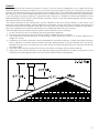
SAFETY NOTICE:
If this heater is not properly installed, a house re
may result. For your safety, follow the installation
instructions. Never use make shift compromises
during the installation of this heater. Contact local
building or re ofcials about permits, restrictions
and installation requirements in your area.
CAUTION!
Please read this entire manual before you
install or use your new room heater. Failure
to follow instructions may result in property
damage, bodily injury, or even death.
Improper Installation Could Void Your
Warranty!
SAVE THESE INSTRUCTIONS
THIS MANUAL WILL HELP YOU TO OBTAIN EFFICIENT, DEPENDABLE SERVICE FROM THE HEATER, AND ENABLE YOU
TO ORDER REPAIR PARTS CORRECTLY. KEEP IN A SAFE PLACE FOR FUTURE REFERENCE.
MODEL: BEC95E(B)
Certied to: UL 1482-11 (R2015) and
Certied to: ULC-S627-00
Not approved for use in mobile homes, do not
install in a mobile home
U.S. Environmental Protection Agency
Certied to comply with 2015 particulate
emissions standards.
CALIFORNIA PROPOSITION 65 WARNING:
This product can expose you to chemicals including carbon monoxide, which
is know to the State of California to cause cancer, birth defects and/or other
reproductive harm. For more information, go to www.P65warnings.ca.gov
Ce produit peut vous exposer à des produits chimiques, y compris le
monoxyde de carbone, qui est connu dans l'État de Californie pour causer
le cancer, des malformations congénitales et / ou d'autres problèmes de
reproduction. Pour plus d'informations, visitez www.P65warnings.ca.gov

2
CONGRATULATIONS!
You’ve purchased a heater from North America’s oldest manufacturer of wood burning products.
By heating with wood you’re helping to CONSERVE ENERGY! Wood is our only Renewable Energy Resource.
Please do your part to preserve our wood supply. Plant at least one tree each year. Future generations will
thank you. The instructions pertaining to the installation of your wood stove comply with UL-1482-11 (R2015), and
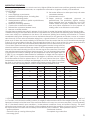
ULC-S627-00 standards. This manual describes the installation and operation of the Ashley, BEC95E(B) wood
heater. This heater meets the 2015 U.S. Environmental Protection Agency’s crib wood emission limits for wood
heaters sold after May 15, 2015. Under specic test conditions this heater has been shown to deliver heat at
rates ranging from 11,817 to 31,713 Btu/hr. Note: The BTU ratings mentioned above are based on the EPA test
protocol burning dimensional Douglas Fir lumber. Our advertised BTU’s are based on the rst hour of operation
at high burn rate burning cordwood.
CAUTIONS:
• Hot while in operation. Keep children, clothing and furniture away. Contact may cause skin burns.
• Do not use chemicals or uids to ignite the re.
• Do not leave the stove unattended when the door is slightly opened.
• Do not burn garbage, ammable uid such as gasoline, naphtha or motor oil.
• Do not connect to any air distribution duct or system.
• Always close the door after the ignition.
Combustible: Wood
Colors: Metallic Black
Flue Pipe Diameter: 6” (152.5mm)
Flue Pipe Type: (Standard Single Wall or Double
Wall):
Black or Blued Steel 2100°F (650°C)
Minimum Chimney Height: 12’ (3.7m)
Maximum Log Length: 21” (533.5mm)
Dimensions
Overall: Depth x Width x Height: 21.5” x 32” x 33.5” (547mm x 813mm x 864mm)
Combustion Chamber: Width x Depth: 11-3/8” x 24-3/4” (289mm x 629mm)
Volume: Cubic Feet: 1.86 ft³ (.0527m³)
Door Opening: Width x Height: 10” x 11-3/8” (854mm x 289mm)
Note: Register your product on line at www.usstove.com. See “Limited Warranty” section for specic warranty
information for your new purchase. Save your receipt with your records for any claims.

3
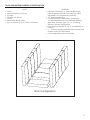
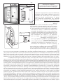
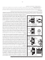
TOOLS AND MATERIALS NEEDED FOR INSTALLATION
Brick Configuration
TOOLS
• Pencil
• Masuring Tape or 6 foot rule
• Tin Snips
• Drill and 1/8” dia. bit
• Gloves
• Screwdriver (Blade type)
• 5/16” Nut Driver or 5/16” Socket w/Ratchet
MATERIALS
• Chimney Connection- 6” Diameter Black Steel
pipe (24 gauge minimum) and elbow(s) either
adjustable1 or corrugated as necessary
• 1/2” Sheet Metal Screws
• 6” Inside Diameter Underwriters Laboratories
(UL) listed Residential Type and Building Heating
Appliance Chimney, Type “HT”, or 6” existing
Masonry Chimney with ue liner.
• Floor Protector Material: 3’ x 4’-6” (as specied on
page 4.)
• • Furnace Cement (Manufacturer recommends:
Rutland Code 78 or Equivalent)
• 1 Avoid adjustable elbows, they leak!

4
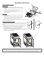
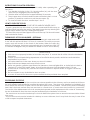
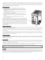
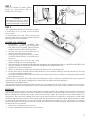
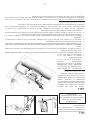
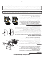
BLOWER ASSEMBLY-OPTIONAL
INSTALLATION
1. Remove the Panel (A) using tin snips or knock out using
a hammer and chisel careful not to distort the mounting
surface.
2. Attach the Blower Mounting Box (B) to the rear of the
unit using four(4) of the supplied #10 screws.
3. Then mount the Blower Assembly with the four(4)
remaining screws.
OPERATION
1. Rotating the rheostat control knob clockwise will turn
ON the blower.
2. When turned on, the blower comes on HIGH, then as the
knob is rotated clockwise, the blower speed reduces.
3. Rotate the knob counter-clockwise to turn OFF.
Caution! Route the Power Supply Cord away from the heat source
and out of high trafc areas.
CABINET DOOR KNOB ASSEMBLY
The cabinet door knob is mounted on the inside of the cabinet door
to facilitate shipping and must be removed and re-installed for proper
usage.
To get the cabinet door open, place your hand under the cabinet
frame (right hand side of the cabinet door) and push door out.
FOLLOW THESE INSTRUCTIONS FOR DOOR KNOB ASSEMBLY:
1. Remove the machine screw and the door knob.
2. Place the knob on the outside of the cabinet door, re-install the
machine screw and tighten being careful not to strip out the
threads in the plastic handle.
Assembly Instructions
MACHINE SCREW
CABINET DOOR KNOB
A
B
C
D
NOTE: During opening and closing of the feed and ash doors of this heater, it may seem that the t of the
door is "too tight". As the heater is red, the gasketing "settles" or "seats" itself in the door. The tight t at the
factory and before the heater's initial ring is to insure a good seal after the gasketing "settles".

5
SAFETY NOTICE
• If this stove is not properly installed, a house re may result. To reduce the risk of re, follow the installation
instructions.
• Consult your municipal building department or re ofcials about permits, restrictions and installations
requirements in your area.
• Use smoke detectors in the room where your stove is installed.
• Keep furniture and drapes well away from the stove.
• Never use gasoline, gasoline-type lantern fuel, kerosene, charcoal lighter uid, or similar liquids to start or
“freshen up” a re in this heater. Keep all such liquids well away from the heater while it is in use.
• In the event of a chimney re, push the air control full closed to deprive the re of oxygen. Call the re
department.
• Do not connect to any air distribution duct or system.
• A source of fresh air into the room or space heated shall be provided when required.
POSITIONING THE STOVE
It is very important to position the wood stove as close as possible to the chimney, and in an area that will favour
the most efcient heat distribution possible throughout the house. The stove must therefore be installed in the
room where the most time is spent, and in the most spacious room possible. Wood stoves produce radiating
heat, that is the heat we feel when we are close to a wood stove. A wood stove also functions by convection.
Convection is the displacement of hot air accelerated upwards and its replacement with cooler air. If necessary,
the hot air distribution from the stove may be facilitated by the installation of a blower.
The wood stove must not be hooked up to a hot air distribution system since an excessive accumulation of heat
may occur.
A wood stove must never be installed in a hallway or near a staircase, since it may block the way in case of re
or fail to respect required clearances.
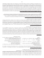
INSTRUCTIONS FOR LATCH OPERATION
Follow these instructions to operate you unit safely when operating the
feed door.
1. Turn handle clockwise to the 12 o’clock position (A), pull the door
open until you engage the second step (B).
2. Hold the door in that position for approximately 10 seconds.
3. Then to open door, turn the handle counter clockwise to the 9 o’clock
position (C) and then continue to pull the door open. (D)
4. To close and latch the door, reverse steps 1 thru 4.
HOW TO OPEN THE TOP LID
CAUTION! DO NOT OPEN OR CLOSE THE TOP WHEN THE HEATER IS HOT!
To open, grasp the top at the front or on each corner and lift all the way up
until the support rod stops the motion. Then gently lower the top allowing the
support rod to settles in the cup, holding the top open.
To Close, lift the top until the support rod is out of the cup. Pull the rod forward
and lower the lid closed.
THERMODISC KIT FOR B36 BLOWER - OPTIONAL
Wish your blower would turn ON and OFF as the heater gets warm and cold?
It can with this optional kit from U.S. Stove. It connects in line with your power
supply cord and mounts to the back of the heater. When the snap disc
reaches 120 degrees, the blower automatically turns ON and turns itself OFF
if it reaches 90 degrees. See your Dealer for details or call U.S. Stove directly.

6
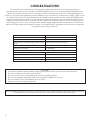
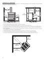
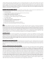
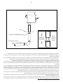
CLEARANCES TO COMBUSTIBLES
It is of utmost importance that the clearances to combustible materials be strictly adhered to during installation
of the stove. Refer to the tables below.
• Floor to ceiling height must be at least 7’ (2.13m) in all cases.
• Do not place any combustible material within 4’ (1.2m) of the front of the unit.
• The clearance between the ue pipe and a wall are valid only for vertical walls and for vertical ue pipe.
• The chimney connector must not pass through an attic or roof space, closet or similar concealed space, a
oor, or a ceiling.
• For Canadian installations, where passage through a wall, or partition of combustible construction is desired,
the installation must conform to CAN/CSA-B365.
• A ue pipe crossing a combustible wall must have a minimum clearance of 18” (457.2mm).
• To reduce ue clearances from combustible materials, contact your local safety department.
• The provision that clearances may only be reduced by means approved by regulatory authority
4 3/4
(121mm)
54
(1.37M)
*16
(407mm)
18
(458mm)
51
(1296mm)
84
(2134mm)
23.25”
(989mm)
12
(305mm)
18
(458mm)
*14
(356mm)
12
(305mm)
36
(914mm)
INCHES (METRIC)
NOTE: DASHED LINES SHOW
STRAIGHTUP AND DOWN THROUGH
THE WALL INSTALLATION.
*CANADIAN INSTALLATIONS REQUIRE
A MINIMUM OF 18” (450mm) ON THE
FUEL LOADING SIDE AND 8”(203mm)
ON ALL OTHER SIDES.
NON-COMBUSTIBLE CONSTRUCTION
IN ACCORDANCE WITH NFPA 211
AND CAN/CSA-B365-M91
18”
(458mm)
12”
(304.8mm)
18”
(458mm)

7
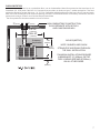
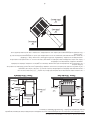
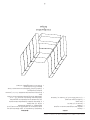
FLOOR PROTECTOR
When the heater is used on a combustible oor, use an Underwriters Listed oor protector that conforms to UL
Standards (UL 1618) and CAN/ULC for Canada, that provides at minimum type 1 ember protection. The oor
protector should be under the stove, 16” (18” for Canadian Instillations)beyond the front and 8” beyond each
side of the fuel loading and ash removal opening. If there is a horizontal section of chimney connector, the oor
protector should go under it and 2 inches beyond each side
The oor protector should exceed the stove as follows:
8”
(204mm)
U.S. 52”
(1321mm)
CAN. 60”
(1524mm)
2”(21mm) 2”(21mm)
12
(305mm)
41.5”
(1055mm)
INCHES (METRIC)
NOTE: DASHED LINES SHOW
STRAIGHTUP AND DOWN THROUGH
THE WALL INSTALLATION.
*CANADIAN INSTALLATIONS REQUIRE
A MINIMUM OF 18” (450mm) ON THE
FUEL LOADING SIDE AND 8”(203mm)
ON ALL OTHER SIDES.
NON-COMBUSTIBLE CONSTRUCTION
IN ACCORDANCE WITH NFPA 211
AND CAN/CSA-B365-M91
Protecteur
de plancher

8
CHIMNEY CONNECTOR (STOVE PIPE)
Your chimney connector and chimney must have the same diameter as the stove outlet (6”). If this is not the
case, we recommend you contact your dealer in order to insure there will be no problem with the draft.
The stove pipe must be made of aluminized or cold roll steel with a minimum thickness of 0.021” or 0.53 mm. It is
strictly forbidden to use galvanized steel.
Your smoke pipe should be assembled in such a way that the male section (crimped end) of the pipe faces
down. Attach each of the sections to one another with three equidistant metal screws.
The pipe must be short and straight. All sections installed horizontally must slope at least 1/4 inch per foot, with
the upper end of the section toward the chimney. Any installation with a horizontal run of chimney pipe must
conform to NFPA 211. You may contact NFPA (National Fire Protection Association) and request the latest edition
of the NFPA Standard 211.
To insure a good draft, the total length of the coupling pipe should never exceed 8’ to 10’ (2.4m to 3.04 m).
(Except for cases of vertical installation, cathedral-roof style where the smoke exhaust system can be much
longer and connected without problem to the chimney at the ceiling of the room).
There should never be more than two 90 degrees elbows in the smoke exhaust system.
Installation of a “barometric draft stabilizer” (replace register) on a smoke exhaust system is prohibited.
Furthermore, installation of a draft damper is not recommended. Indeed, with a controlled combustion wood
stove, the draft is regulated upon intake of the combustion air in the stove and not at the exhaust.
IMPORTANCE OF PROPER DRAFT
Draft is the force which moves air from the appliance up through the chimney. The amount of draft in your
chimney depends on the length of the chimney, local geography, nearby obstructions and other factors. Too
much draft may cause excessive temperatures in the appliance. Inadequate draft may cause backpufng into
the room and ‘plugging’ of the chimney. Inadequate draft will cause the appliance to leak smoke into the room
through appliance and chimney connector joints. An uncontrollable burn or excessive temperature indicates
excessive draft.

9
CHIMNEY
Take into account the chimney’s location to insure it is not too close to neighbours or in a valley which may
cause unhealthy or nuisance conditions. Your wood stove may be hooked up with a 6” factory built or masonry
chimney. If you are using a factory built chimney, it must comply with UL 103 or CSA-B365 standard; therefore it must
be a Type HT (2100°F). It is extremely important that it be installed according to the manufacturer’s specications.
If you are using a masonry chimney, it is important that it be built in compliance with the specications of the
National Building Code. It must be lined with re clay bricks, metal or clay tiles sealed together with re cement.
(Round ues are the most efcient).
The interior diameter of the chimney ue must be identical to the stove smoke exhaust. A ue which is too
small may cause draft problems, while a large ue favours rapid cooling of the gas, and hence the build-up of
creosote and the risk of chimney res. Note that it is the chimney and not the stove which creates the draft effect;
your stove’s performance is directly dependent on an adequate draft from your chimney.
The following recommendations may be useful for the installation of your chimney:
1. Do not connect this unit to a chimney ue serving another appliance.
2. It must rise above the roof at least 3’ (0.9m) from the uppermost point of contact.
3. The chimney must exceed any part of the building or other obstruction within a 10’ (3.04m) distance by a
height of 2’ (0.6m).
4. Installation of an interior chimney is always preferable to an exterior chimney. Indeed, the interior chimney
will, by denition, be hotter than an exterior chimney, being heated up by the ambient air in the house.
Therefore the gas which circulates will cool more slowly, thus reducing the build-up of creosote and the risk
of chimney res.
5. The draft caused by the tendency for hot air to rise will be increased with an interior chimney.
6. Using a re screen at the extremity of the chimney requires regular inspection in order to insure that it is not
obstructed thus blocking the draft, and it should be cleaned when used regularly.

10
FACTORY BUILT CHIMNEY
When a metal prefabricated chimney is used, the manufacturer’s installation instructions must be followed. You
must also purchase (from the same manufacturer) and install the ceiling support package or wall pass-through
and “T” section package, restops (where needed), insulation shield, roof ashing, chimney cap, etc. Maintain
proper clearance to the structure as recommended by the manufacturer. The chimney must be the required
height above the roof or other obstructions for safety and proper draft operation.

11
MASONRY CHIMNEY
Ensure that a masonry chimney meets the minimum standards of the National Fire Protection Association (NFPA)
by having it inspected by a professional. Make sure there are no cracks, loose mortar or other signs of deterioration
and blockage. Have the chimney cleaned before the stove is installed and operated. When connecting the
stove through a combustible wall to a masonry chimney, special methods are needed.

12
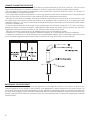
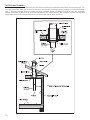
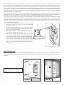
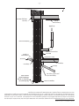
COMBUSTIBLE WALL CHIMNEY CONNECTOR PASS-THROUGHS
Method A. 12” (304.8 mm) Clearance to Combustible Wall
Member: Using a minimum thickness 3.5” (89 mm) brick and a
5/8” (15.9 mm) minimum wall thickness clay liner, construct a
wall pass-through. The clay liner must conform to ASTM C315
(Standard Specication for Clay Fire Linings) or its equivalent.
Keep a minimum of 12” (304.8 mm) of brick masonry between
the clay liner and wall combustibles. The clay liner shall run
from the brick masonry outer surface to the inner surface of the
chimney ue liner but not past the inner surface. Firmly grout or
cement the clay liner in place to the chimney ue liner.
Method B. 9” (228.6 mm) Clearance to Combustible Wall
Member: Using a 6” (152.4 mm) inside diameter, listed, factory-
built Solid-Pak chimney section with insulation of 1” (25.4 mm) or
more, build a wall pass-through with a minimum 9” (228.6 mm)
air space between the outer wall of the chimney length and
wall combustibles. Use sheet metal supports fastened securely
to wall surfaces on all sides, to maintain the 9” (228.6 mm) air
space. When fastening supports to chimney length, do not
penetrate the chimney liner (the inside wall of the Solid-Pak
chimney). The inner end of the Solid-Pak chimney section shall
be ush with the inside of the masonry chimney ue, and sealed
with a non-water soluble refractory cement. Use this cement to
also seal to the brick masonry penetration.
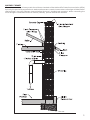
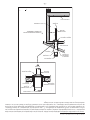
Method C. 6” (152.4 mm) Clearance to Combustible Wall
Member: Starting with a minimum 24 gage (.024” [.61 mm])
6” (152.4 mm) metal chimney connector, and a minimum 24
gage ventilated wall thimble which has two air channels of 1”
(25.4 mm) each, construct a wall pass-through. There shall be a
minimum 6” (152.4) mm separation area containing berglass
insulation, from the outer surface of the wall thimble to wall
combustibles. Support the wall thimble, and cover its opening
with a 24-gage minimum sheet metal support. Maintain the 6”
(152.4 mm) space. There should also be a support sized to t
and hold the metal chimney connector. See that the supports
are fastened securely to wall surfaces on all sides. Make sure
fasteners used to secure the metal chimney connector do not
penetrate chimney ue liner.
Method D. 2” (50.8 mm) Clearance to Combustible Wall
Member: Start with a solid-pak listed factory built chimney
section at least 12” (304 mm) long, with insulation of 1” (25.4
mm) or more, and an inside diameter of 8” (2 inches [51 mm]
larger than the 6” [152.4 mm] chimney connector). Use this as a
pass-through for a minimum 24-gauge single wall steel chimney
connector. Keep solid-pak section concentric with and spaced
1” (25.4 mm) off the chimney connector by way of sheet
metal support plates at both ends of chimney section. Cover
opening with and support chimney section on both sides with
24 gage minimum sheet metal supports. See that the supports
are fastened securely to wall surfaces on all sides. Make sure
fasteners used to secure chimney ue line.
NOTES:
1. Connectors to a masonry chimney, excepting method B, shall extend in one continuous section through the
wall pass-through system and the chimney wall, to but not past the inner ue liner face.
2. A chimney connector shall not pass through an attic or roof space, closet or similar concealed space, or a
oor, or ceiling.

13
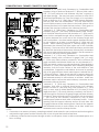
WOODSTOVE UTILIZATION
This heater is designed to burn natural wood only. Higher efciencies and lower emissions generally result when
burning air dried seasoned hardwoods, as compared to softwoods or to green or freshly cut hardwoods.
DO NOT BURN:
1. Garbage;
2. Lawn clippings or yard waste;
3. Materials containing rubber, including tires;
4. Materials containing plastic;
5. Waste petroleum products, paints or paint thinners,
or asphalt products;
6. Materials containing asbestos;
7. Construction or demolition debris;
8. Railroad ties or pressure-treated wood;
9. Manure or animal remains;
10. Salt water driftwood or other previously salt water
saturated materials;
11. Unseasoned wood; or
12. Paper products, cardboard, plywood, or
particleboard. The prohibition against burning
these materials does not prohibit the use of re
starters made from paper, cardboard, saw dust,
wax and similar substances for the purpose of
starting a re in an affected wood heater.
Burning these materials may result in release of toxic fumes or render the heater ineffective and cause smoke.
Dead wood lying on the forest oor should be considered wet, and requires full seasoning time. Standing dead
wood can usually be considered to be about 2/3 seasoned. Splitting and stacking wood before it is stored
accelerates drying time. Storing wood on an elevated surface from the ground and under a cover or covered
area from rain or snow also accelerates drying time. A good indicator if wood is ready to burn is to check the
piece ends. If there are cracks radiating in all directions from the center then the wood should be dry enough
to burn. If your wood sizzles in the re, even though the surface is dry, it may not be fully cured, and should be
seasoned longer. Waste and other ammable materials should not be burned in your stove.
Do not burn manufactured logs made of wax impregnated sawdust or logs with any
chemical additives. Manufactured logs made of 100% compressed sawdust can be
burned, but be careful burning too much of these logs at the same time. Start with
one manufactured log and see how the stove reacts. You can increase the number
of logs burned at a time to making sure the temperature never rises higher than 475
°F (246 °C) on a magnetic thermometer for installation on single wall stove pipes or
900 °F (482 °C) on a probe thermometer for installation on double wall stove pipe.
The thermometer should be placed about 18” (457 mm) above the stove. Higher
temperatures can lead to overheat and damage your stove. Any type of wood may
be used in your stove, but specic varieties have better energy yields than others.
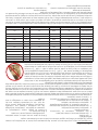
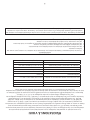
Please consult the following table in order to make the best possible choice.
It is EXTREMELY IMPORTANT that you use DRY WOOD only in your wood stove. The wood should have dried for 9
to 15 months, such that the humidity content (in weight) is reduced below 20% of the weight of the log. It is very
important to keep in mind that even if the wood has been cut for one, two or even more years, it is not necessarily
dry, if it has been stored in poor conditions. Under extreme conditions it may rot instead of drying. This point
cannot be over stressed; the vast majority of the problems related to the operation of a wood stove is caused by
the fact that the wood used was too damp or had dried in poor conditions. These problems can be:
- ignition problems
- creosote build-up causing chimney res
- low energy yield
- blackened windows
- incomplete log combustion
TYPE WEIGHT (LBS. CU. FT., DRY) PER CORD EFFICIENCY RANKING SPLITS MILLIONS BTU’s/CORD
Hickory 63 4500 1.0 Well 31.5
White Oak 48 4100 .9 Fair 28.6
Red Oak 46 3900 .8 Fair 27.4
Beech 45 3800 .7 Hard 26.8
Sugar Maple 44 3700 .6 Fair 26.2
Black Oak 43 3700 .6 Fair 25.6
Ash 42 3600 .5 Well 25.0
Yellow Birch 40 3400 .4 Hard 23.8
Red Maple 38 3200 .3 Fair 22.6
Paper Birch 37 3100 .3 Easy 22.1
Elm/Sycamore 34 2900 .2 Very Difcult 20.1
Red Spruce 29 1800 .1 Easy 16.1

14
Smaller pieces of wood will dry faster. All logs exceeding 6” in diameter should be split. The wood should not be
stored directly on the ground. Air should circulate through the cord. A 24” to 48” air space should be left between
each row of logs, which should be placed in the sunniest location possible. The upper layer of wood should be
protected from the elements but not the sides.
OPERATIONAL TIPS
• Operational Tips for Good, Efcient, and Clean Combustion
• Get the appliance hot and establish a good coal bed before
adjusting to a low burn rate (this may take 30 minutes or more
depending on your wood)
• Use smaller pieces of wood during start-up and a high burn rate
to increase the stove temperature
• Be considerate of the environment and only burn dry wood
• Burn small, intense res instead of large, slow burning res when
possible
• Learn your appliance’s operating characteristics to obtain
optimum performance
Burning unseasoned wet wood only hurts your stoves efciency and
leads to accelerated creosote buildup in your chimney. The clean
outs are secured to the rebox with (2) 5/16” screws. Remove the
clean outs and vacuum out any accumulated ash. This should be
done at least once per month or more frequently if large amounts of
ash are noticed while cleaning or if the stove does not seem to be
burning properly. The ring and ash doors must be closed and sealed
during operation.
TESTING YOUR WOOD
When the stove is thoroughly warmed, place one piece of split wood (about ve inches in diameter) parallel to
the door on the bed of red embers.
Keep the air control full open by pulling on it and close the door. If ignition of the piece is accomplished within
90 seconds from the time if was placed in the stove, your wood is correctly dried. If ignition takes longer, your
wood is damp.
If your wood hisses and water or vapor escapes at the ends of the piece, your wood is soaked or freshly cut.
Do not use this wood in your stove. Large amounts of creosote could be deposited in your chimney, creating
potential conditions for a chimney re.
TAMPER WARNINGS
This wood heater has a manufacturer-set minimum low burn rate that must not be altered. It is against federal
regulations to alter this setting or otherwise operate this wood heater in a manner inconsistent with operating
instructions in this manual.
THE FIRST FIRES
The fresh paint on your stove needs to be cured to preserve its quality. Once the fuel charge is properly ignited,
only burn small res in your stove for the rst four hours of operation. Never open the air control more than
necessary to achieve a medium burn rate.
Make sure that there’s enough air circulation while curing the stove. The odors could be smelled during the 3 or
4 rst res. Never start your stove outside. You will not be able to see if you are over heating.
IGNITION
The top down method of re building is recommended for this appliance. Place the largest pieces of wood on
the bottom, laid in parallel and close together. Smaller pieces are placed in a second layer, crossways to the
rst. A third layer of still smaller pieces is laid crossways to the second, this time with some spaces between. Then
a fourth layer of loose, small kindling and twisted newspaper sheets tops off the pile.
CAUTION: Never alter the damper slide or the adjustment range to increase ring for any reason. Doing so
could result in heater damage and will void your warranty.
Air
Cleanouts

15
Before igniting the paper and kindling wood, it is recommended that you warm up the chimney. This is done
in order to avoid back draft problems often due to negative pressure in the house. If such is the case, open a
window slightly near the stove and twist together a few sheets of newspaper into a torch. Light up this paper
torch and hold it as close as possible to the mouth of the pipe inside the combustion chamber to warm up the
chimney. Once the up-draft movement is initiated, you are ready to ignite the stove by lighting the paper and
kindling wood inside the combustion chamber.
POSSIBLE FLUE OR CHIMNEY DEFECTS
From the foregoing basic principles for the regulation of chimney ues, it will be seen that unsatisfactory stove
operation may be the result of any of the following possible chimney ue defects:
1. Insufcient height.
2. Surrounding nearby objects throwing air currents down the chimney.
3. Flues enlarged or contracted at some point.
4. Rubbish or soot obstruction in the ue.
5. Air leakage in cracks where mortar has fallen out.
6. Floor support or a pipe passing through or entering the ue.
7. Too abrupt offsets.
8. Other connecting ues
9. Chimney being used for ventilating basement
10. Chimneys too large for stove being used.
11. Flues being long and narrow
12. More than one smoke-pipe connected to the ue.
13. Chimney connector protruding too far into the chimney.
FUEL
Seasoned cordwood will give the most heat. Your heater will burn most any type of cordwood. Seasoned
hardwood produces more heat, and will hold a re longer, leaving a hotter coal bed than seasoned softwood.
Coal should never be used in a heater designed for burning wood. Never use driftwood that has been in salt water.
The salt content will cause corrosion that will destroy the stainless steel in the Class A chimney, the ue connector
and the rebox. Hard wood cut to 20” maximum length, and split 3” to 6” cross section is recommended for best
operating efciency. CAUTION: Burn untreated cordwood only. Wood containing preservative, metal foils, coal,
plastic, garbage, sulphur or oil is environmentally hazardous and will damage the appliance.
LOADING OF FUEL
Do not overll the rebox above the rebrick. Wood should be 3 to 4” below top of rebrick. A burned-out heat
chamber may result. Do not use articial or wax logs. Build re on the oor of the stove. Do not use additional
grates or andirons to support the re as these may create excessive heat. For the most heat, combustion air must
be able to circulate around and through the re. Do not block the air entrances inside the rebox with ashes.
When loading each additional fuel charge, clear the ashes away from the lower primary air orices behind the
bottom of the door opening.
PREPARATION AND STORAGE OF FUEL
Solid fuel should be cut and split prior to the heating season and stored in a well, aired dry place. Do not store
fuel within the room heater clearances or within the space required for fuelling or ash removal. Fuel should be
kept at least 5ft clear (1.5m) from the heater. The space around the heater should be kept free of litter and wood
residue.
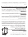
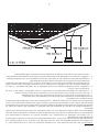
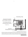
TYPES OF COMBUSTION AIR FOR WOOD HEATING
Unlike older airtight box stoves, low emission woodstoves have more than one location and control for supplying
combustion air into the rebox. These additional air inlets allow for complete combustion of wood gases and
particulates. Thus it is important to understand how these different air supplies work. PRIMARY AIR starts the re.
Opening or closing this air supply then regulates how fast the stove will burn. Primary air is supplied by the following:
a dial with settings for burn rates and a thermostat. Use the Primary Air Control (PAC) dial (on right) to control the
burn. Adjust the settings to obtain the desired heat output. Always start a re with the PAC set on high and leave
it on high until the secondary ames continue to burn after the PAC has been adjusted to a lower setting. Reset
the PAC to high when reloading. The thermostat also controls the amount of primary air entering the unit. Set it
on “Open” when starting a re and leave it on “Open” until the stove has been burning long enough to keep the
secondary ames burning when it is closed. Set the thermostat on “Open” for 10 to 20 minutes when reloading.
It is very important to keep the secondary ames burning to maximize heat output and minimize air pollution, so
some experimentation will be necessary because each installation is different. Wood moisture content will also
affect the amount of time that a unit will need to burn on high after each reload.

16
SECONDARY AIR allows the woodstove to burn clean. This preheated air enters the upper rebox just below
the bafe plate. This superheated air mixed with the wood gases and ames ignites, reaching temperatures in
this unit range. Without Secondary Air these volatile gases would exit the stove unburned as creosote, smoke,
particulates, and high levels of Carbon Monoxide, greatly decreasing efciency. Heat comes from burning the
wood gases, not the wood, which itself turns into black charcoal after the gases are all released. Secondary air
increases a stoves efciency by approximately 40% greatly reducing the amount of wood required for a heating
season (easily up to 1/3 less wood).
Secondary air timer (SAT) located on the left side of this appliance. Never attempt to burn your stove with the
timer knob set in the off position. This closes Off the secondary air and your stove will burn dirty and produce
creosote. The SAT should be left in the open position and locked with the timer stop lever set on
“Hi” and your stove will burn optimally. It is not necessary to use the timer except if you Wish to extend the length
of the coal bed time, after the wood has nished burning The Secondary Air Timer (SAT) is used to control the
duration of secondary air entering the stove. When burning the stove be sure the timer is set to open (Timer Knob
past One Hour and Timer Lever to “HI”. The SAT is only used if you wish to extend the coal bed time on Medium
Low or Low setting. To do so:
1. GENTLY rotate Timer Knob clockwise to 2.5 to 3 hours for
Medium Low and 3 to 3.5 hours for Low as designated
on the timer plate.
2. Turn the timer lever down to ”LO” to allow the timer
to close. Observe that the timer closes after there
are no more ames present
3. THE TIMER MUST BE OPENED AND THE LEVER SET TO
“HI” BEFORE ADDING MORE FUEL.
4. The above settings are based upon a 15 foot
chimney. The actual settings may vary slightly due to
your chimney height and the outside temperatures.
Taller chimneys and colder outside temperatures
cause a stove to burn faster. This means the SA timer
does not have to be opened as long. The same is
true of wood moisture – drier fuel will burn faster than
wetter fuel.
HI
Twist Lever
To Adjust
LOW
HI
Twist Lever
To Adjust
LOW
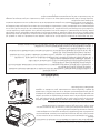
TIMER INSTRUCTIONS
The timer assembly on this unit requires periodic maintenance to ensure proper operation. Locate the timer on
the left-hand side of the appliance, then follow the steps below to facilitate the annual cleaning of the timer
assembly.
STEP 2
STEP 1
CAUTION: Allow the stove to cool
completely before carrying out
any maintenance or cleaning

17
STEP 3
Using a canned air duster, gently
spray any accumulative dust or
buildup off of the timer.
STEP 4
Use a general machine oil (3-IN-ONE) to apply
a small drop of oil to each of the locations
shown below.
To reassemble the timer simply reverse the
previous steps. Ensure proper operation before
attaching the nal cover plate.
LIGHTING AND OPERATION
1. IMPORTANT! – NEVER OPERATE THIS
WOODSTOVE WITHOUT THE SECONDARY
AIR TIMER IN THE LOCKED OPEN POSITION
WHEN LIGHTING A FIRE OR RELOADING!
2. Set the PAC dial and the thermostat on
HIGH to provide maximum draft.
3. Note that the Secondary Air Inlet is in the”
LOCKED OPEN POSITION” on the left side of
the stove.
4. Open loading door and lay re, using
ample kindling to ensure rapid ignition.
5. Prime chimney if necessary holding lighted newspaper up towards ue bafe. A CANDLE WORKS BEST AND
WILL NOT SMOKE UP THE ROOM IF THE COLD AIR BLOWS THE NEWSPAPER OUT.
6. Light re and close loading door.
7. Wait 3 - 5 minutes then add seasoned rewood. (See section concerning Fuel).
8. Set the PAC dial to maintain desired temperature in room. Medium setting is normally satisfactory. Set high
or lower for desired temperature.
9. Once re is established set the Burn Rate dial to the desired rate. This will maintain a steady temperature after
the thermostat closes.
CAUTION: Do not operate this heater with the loading door open. Continuous operation with a door open will
over heat the unit. This heater is designed for Thermostatic and Burn Rate Dial operation.
THERMOSTAT ADJUSTMENT DIAL
The adjustment plate in the thermostat may be set to change the burn rate. Open to increase and close to
decrease burn rate. Leave adjustment for a few days after changing to see if burn rate is better for your situation.
REFUELLING
CAUTION: Read the section on back-pufng before refuelling heater. The loading door should be closed at all
times except when refuelling. If the door is allowed to remain open, the thermostat will not function, as it should.
Before opening the loading door, make sure the thermostat is open. Allow the re to burn rather briskly for a
few minutes. Then open the loading door slowly. By allowing the re to increase for a short period, a high draft
condition has eliminated smoke in the rebox and the temperature has been raised which prevents a back
or down draft. After refueling, run the dial on High and thermostat on open for 10 to 30 minutes to insure the
secondaries ignite and stay lit when the air controls are adjusted to the desired settings. Keeping the secondaries
lit is important for two reasons:
1. More heat is obtained from the wood
2. Smoke is particulate matter which is air pollution
WARNING:
Be careful not to use too much
air pressure as this may cause
potential damage to the timer

18
HEATING
Controlled combustion is the most efcient technique for wood heating because it enables you to select the type
of combustion you want for each given situation. The wood will burn slowly if the wood stove air intake control is
adjusted to reduce the oxygen supply in the combustion chamber to a minimum. On the other hand, wood will
burn quickly if the air control is adjusted to admit a larger quantity of oxygen in the combustion chamber. Real
operating conditions may give very different results than those obtained during testing according to the species
of wood used, its moisture content, the size and density of the pieces, the length of the chimney, altitude and
outside temperature.
EFFICIENCY
Efciencies can be based on either the lower heating value (LHV) or the higher heating value (HHV) of the fuel.
The lower heating value is when water leaves the combustion process as a vapor, in the case of woodstoves the
moisture in the wood being burned leaves the stove as a vapor. The higher heating value is when water leaves
the combustion process completely condensed. In the case of woodstoves this would assume the exhaust gases
are room temperature when leaving the system, and therefore calculations using this heating value consider
the heat going up the chimney as lost energy. Therefore, efciency calculated using the lower heating value of
wood will be higher than efciency calculated using the higher heating value. In the United States all woodstove
efciencies should be calculated using the higher heating value. The best way to achieve optimum efciencies
is to learn the burn characteristic of you appliance and burn well-seasoned wood. Higher burn rates are not
always the best heating burn rates; after a good re is established a lower burn rate may be a better option for
efcient heating. A lower burn rate slows the ow of usable heat out of the home through the chimney, and it
also consumes less wood.
VISIBLE SMOKE
The amount of visible smoke being produced can be an effective method of determining how efciently the
combustion process is taking place at the given settings. Visible smoke consist of unburned fuel and moisture
leaving your stove. Learn to adjust the air settings of your specic unit to produce the smallest amount of visible
smoke. Wood that has not been seasoned properly and has a high wood moisture content will produce excess
visible smoke and burn poorly.
CREOSOTE FORMATION AND NEED FOR REMOVAL
When wood is burned slowly, it produces tar and other organic vapors, which combine with expelled moisture
to form creosote. The creosote vapors condense in the relatively cool chimney ue of a slow-burning re. As a
result, creosote residue accumulates on the ue lining. When ignited this creosote makes an extremely hot re.
The chimney connector and chimney should be inspected at least once every two months during the heating
season to determine if a creosote build-up has occurred. If creosote has accumulated (3mm or more), it should
be removed to reduce the risk of a chimney re. We strongly recommend that you install a magnetic thermometer
on your smoke exhaust pipe, approximately 18” above the stove. This thermometer will indicate the temperature
of your gas exhaust fumes within the smoke exhaust system. The ideal temperature for these gases is somewhere
between 275°F and 500°F. Below these temperatures, the build-up of creosote is promoted. Above 500 degrees,
heat is wasted since a too large quantity is lost into the atmosphere.
TO PREVENT CREOSOTE BUILD UP
• Always burn dry wood. This allows clean burns and higher chimney temperatures, therefore less creosote
deposit.
• Leave the air control full open for about 5 min. every time you reload the stove to bring it back to proper
operating temperatures. The secondary combustion can only take place if the rebox is hot enough.
• Always check for creosote deposit once every two months and have your chimney cleaned at least once a
year.
If a chimney or creosote re occurs, close all dampers immediately. Wait for the re to go out and the heater to
WARNING:
• Never over re your stove. If any part of the stove starts to glow red, over ring is happening. Readjust the
air intake control at a lower setting.
• The installation of a log cradle or grates is not recommended in your wood stove. Build re directly on
rebrick.
• Never put wood above the rebrick lining of the rebox.
• Attempts to achieve heat output rates that exceed heater design specications can result in permanent
damage to the heater.

19
cool, then inspect the chimney for damage. If no damage results, perform a chimney cleaning to ensure there is
no more creosote deposits remaining in the chimney.
ASH DISPOSAL
Whenever ashes get 3 to 4 inches deep in your rebox or ash pan, and when the re has burned down and
cooled, remove excess ashes. Leave an ash bed approximately 1 inch deep on the rebox bottom to help
maintain a hot charcoal bed. Ashes should be placed in a metal container with a tight-tting lid. The closed
container of ashes should be placed on a noncombustible oor or on the ground, away from all combustible
materials, pending nal disposal. The ashes should be retained in the closed container until all cinders have
thoroughly cooled.
SMOKE AND CO MONITORS
Burning wood naturally produces smoke and carbon monoxide(CO) emissions. CO is a poisonous gas when
exposed to elevated concentrations for extended periods of time. While the modern combustion systems in
heaters drastically reduce the amount of CO emitted out the chimney, exposure to the gases in closed or conned
areas can be dangerous. Make sure your stove gaskets and chimney joints are in good working order and sealing
properly to ensure unintended exposure. It is recommended that you use both smoke and CO monitors in areas
having the potential to generate CO.
MAINTENANCE
Your wood stove is a high efciency stove and therefore requires little maintenance. It is important to perform
a visual inspection of the stove every time it is emptied, in order to insure that no parts have been damaged,
in which case repairs must be performed immediately. Inspect and clean the chimney and connector pipe
periodically for creosote build-up or obstructions.
GASKETING
This unit’s door uses a 1 inch diameter rope gasket. It is recommended that you change the door gasket (which
makes your stove door air tight) once a year, in order to insure good control over the combustion, maximum
efciency and security. To change the door gasket, simply remove the damaged one. Carefully clean the
available gasket groove, apply a high temperature silicone sold for this purpose, and install the new gasket. You
may light up your stove again approximately 24 hours after having completed this operation.
PAINT
Only clean your stove with a dry soft cloth that will not harm the paint nish. If the paint becomes scratched or
damaged, it is possible to give your wood stove a brand new look, by repainting it with a 1200° F heat resistant
paint. For this purpose, simply scrub the surface to be repainted with ne sand paper, clean it properly, and apply
thin coats (2) of paint successively.
Attention:
This wood heater needs periodic inspection and repair for proper operation. It is against federal regulations
to operate this wood heater in a manner inconsistent with operating instructions in this manual.
CAUTIONS:
• Ashes could contain hot embers even after two days without operating the stove.
• The ash pan can become very hot. Wear gloves to prevent injury.
• Never burn the stove with the ash trap open. This would result in over ring the stove. Damage to the stove
and even house re may result.
WARNING:
Never operate the stove without a gasket or with a broken one
Damage to the stove or even house re may result

20
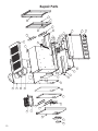
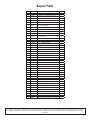
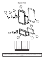
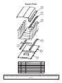
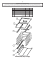
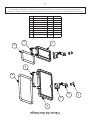
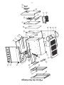
Repair Parts
1
2
3
9
8
7
6
5
4
12
11
10
42
41
28
13
14
17
15
16
17
20
19
23
22
24
25
26
27
29
30
31
32
33
37
38
3435
36
40
39
21
43
44
La page est en cours de chargement...
La page est en cours de chargement...
La page est en cours de chargement...
La page est en cours de chargement...
La page est en cours de chargement...
La page est en cours de chargement...
La page est en cours de chargement...
La page est en cours de chargement...
La page est en cours de chargement...
La page est en cours de chargement...
La page est en cours de chargement...
La page est en cours de chargement...
La page est en cours de chargement...
La page est en cours de chargement...
La page est en cours de chargement...
La page est en cours de chargement...
La page est en cours de chargement...
La page est en cours de chargement...
La page est en cours de chargement...
La page est en cours de chargement...
La page est en cours de chargement...
La page est en cours de chargement...
La page est en cours de chargement...
La page est en cours de chargement...
La page est en cours de chargement...
La page est en cours de chargement...
La page est en cours de chargement...
La page est en cours de chargement...
La page est en cours de chargement...
La page est en cours de chargement...
La page est en cours de chargement...
La page est en cours de chargement...
-
 1
1
-
 2
2
-
 3
3
-
 4
4
-
 5
5
-
 6
6
-
 7
7
-
 8
8
-
 9
9
-
 10
10
-
 11
11
-
 12
12
-
 13
13
-
 14
14
-
 15
15
-
 16
16
-
 17
17
-
 18
18
-
 19
19
-
 20
20
-
 21
21
-
 22
22
-
 23
23
-
 24
24
-
 25
25
-
 26
26
-
 27
27
-
 28
28
-
 29
29
-
 30
30
-
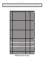 31
31
-
 32
32
-
 33
33
-
 34
34
-
 35
35
-
 36
36
-
 37
37
-
 38
38
-
 39
39
-
 40
40
-
 41
41
-
 42
42
-
 43
43
-
 44
44
-
 45
45
-
 46
46
-
 47
47
-
 48
48
-
 49
49
-
 50
50
-
 51
51
-
 52
52


United States Stove BEC95E Le manuel du propriétaire
- Catégorie
- Poêles
- Taper
- Le manuel du propriétaire
dans d''autres langues
Documents connexes
-
United States Stove 3000 (L) Manuel utilisateur
-
-
Ashley Hearth Products AF1300E Le manuel du propriétaire
-
-
-
Ashley AF1500E Le manuel du propriétaire
Autres documents
-
US Stove Company US2500E-BP Le manuel du propriétaire
-
-
United States Stove Company VG1120 Series Le manuel du propriétaire
-
US Stove Company US2000E Series Le manuel du propriétaire
-
-
-
-
USSC AF1600E Mode d'emploi
-
-
 Drolet FX 2000 WOOD STOVE Manuel utilisateur
