Dell W-Series 228 Access Points Le manuel du propriétaire
- Catégorie
- Points d'accès WLAN
- Taper
- Le manuel du propriétaire

Dell Networking W-IAP228 Wireless Instant Access Point
Installation Guide
0511760-01 | May 2015 1
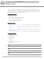
The Dell W-IAP228 is a temperature-hardened, water-resistant, indoor-rated, dual-radio IEEE 802.11ac wireless
Instant Access Point (IAP). It uses MIMO (Multiple-Input, Multiple-Output) technology and other high-
throughput mode techniques to deliver high-performance, 802.11ac 2.4 GHz and 5 GHz functionality while
simultaneously supporting existing 802.11a/b/g/n wireless services.
W-IAP228 Features
Wireless transceiver
Wireless Instant access point (IEEE 802.11 a/b/g/n/ac)
Wireless air monitor (IEEE 802.11 a/b/g/n/ac)
Protocol-independent networking functionality
Compatibility with IEEE 802.3at PoE
Guide Overview
“W-IAP228 Hardware Overview” on page2 provides detailed hardware overview of the W-IAP228 Instant
access point.
“Before You Begin” on page4 provides key questions to ask and items to consider when deploying a wireless
network.
“Installing the IAP” on page5 describes the multi-step process for successful installation and deployment of
the W-IAP228 Instant access point.
“Safety and Regulatory Compliance” on page10 provides safety and regulatory compliance information.
Package Contents
W-IAP228 Instant Access Point
Cable Glands x2
USB Console Cable
Copper Lug x1
M4 x 8 Screw x1
Installation Guide (this document)
Quick Start Guide
NOTE: The weatherproof caps for Ethernet and Console interfaces are connected to the IAP in the package.
NOTE: Mounting kits for use with the W-IAP228 Instant access point are sold separately. Contact your Dell sales representative
for details.
NOTE: Inform your supplier if there are any incorrect, missing, or damaged parts. If possible, retain the carton, including the
original packing materials. Use these materials to repack and return the unit to the supplier if needed.

2 Dell Networking W-IAP228 Wireless Instant Access Point | Installation Guide
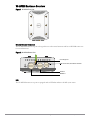
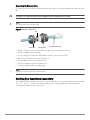
W-IAP228 Hardware Overview
Figure 1
W-IAP228 Front View
External Antenna Connectors
The W-IAP228 Instant access point is designed for use with external antennas and has six RP-SMA connectors
for external antennas.
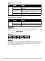
Figure 2
W-IAP228 Bottom View
LED
The W-IAP228 Instant access point is equipped with an LED that indicates the IAP system status.
*
*
*
*
*
*
LAN Port
WAN Port
Grounding Point
USB Console Port, Reset Button and LED

Dell Networking W-IAP228 Wireless Instant Access Point | Installation Guide 3
Table 1
W-IAP228 LED Status during Boot Up
Table 2
W-IAP228 LED Status during Operation
USB Console Port
The USB Micro-B console port allows you to connect the IAP to a terminal or a laptop for direct local
management. Use the included USB console cable to connect the IAP. You can download the necessary driver for
USB-UART adapter from download.dell-pcw.com under the Tools & Resources tab.
Use the following setting to access the terminal:
Ethernet Ports
The W-IAP228 Instant access point is equipped with two 10/100/1000Base-T (RJ-45) Gigabit Ethernet ports
(WAN and LAN port) for wired network connectivity. The WAN port supports 802.3at Power over Ethernet
(PoE), accepting 48 VDC (nominal) as a standard defined Powered Device (PD) from a Power Sourcing
Equipment (PSE) such as a PoE midspan injector.
These ports have RJ-45 female connectors with the pin-outs shown in Figure 3.
LED Color/State Meaning
System LED Off No power to IAP
Red Initial power-up
Green - Flashing IAP booting
Green - Steady IAP ready and 1000Mbps Ethernet link established. The LED turns off
after 1200 seconds
Green - Yellow, 6 seconds
period
IAP ready and 10/100Mbps Ethernet link established. The LED turns off
after 1200 seconds
LED Color/State Meaning
System LED Solid Red General fault
One blink off every 3 seconds Radio 0 fault (5 GHz)
Two quick blink off 0.5 seconds
apart cycled every 3 seconds
Radio 1 fault (2.4GHz)
Table 3
Console Settings
Baud Rate Data Bits Parity Stop Bits Flow Control
9600 8 None 1 None

4 Dell Networking W-IAP228 Wireless Instant Access Point | Installation Guide
Figure 3
Gigabit Ethernet Port Pin-Out
Reset Button
The reset button can be used to return the IAP to factory default settings. To reset the IAP:
1. Power off the IAP.
2. Press and hold the reset button using a small, narrow object, such as a paperclip.
3. Power-on the IAP without releasing the reset button. The system LED will flash within 5 seconds.
4. Release the reset button.
The system LED will flash again within 15 seconds indicating that the reset is completed. The IAP will now
continue to boot with the factory default settings.
Grounding Point
Always remember to protect the IAP by installing grounding lines. The ground connection must be complete
before connecting power to the IAP enclosure.
Figure 4
W-IAP228 Rear View
Before You Begin
1000Base-T Gigabit
Ethernet Port
RJ-45 Female
Pin-Out
Signal Name
1
2
3
4
5
6
7
8
BI_DC+
BI_DC-
BI_DD+
BI_DD-
BI_DA+
BI_DA-
BI_DB+
BI_DB-
Function
Bi-directional pair +C, PoE Positive
Bi-directional pair -C, PoE Positive
Bi-directional pair +D, PoE Negative
Bi-directional pair -D, PoE Negative
Bi-directional pair +A, PoE Negative
Bi-directional pair -A, PoE Negative
Bi-directional pair +B, PoE Positive
Bi-directional pair -B, PoE Positive
CAUTION: To meet regulatory restrictions, the access point must be professionally installed.
CAUTION: FCC Statement: Improper termination of access points installed in the United States configured to non-US model
controllers will be in violation of the FCC grant of equipment authorization. Any such willful or intentional violation may result in a
requirement by the FCC for immediate termination of operation and may be subject to forfeiture (47 CFR 1.80).

Dell Networking W-IAP228 Wireless Instant Access Point | Installation Guide 5
Identifying Specific Installation Locations
Use the AP placement map generated by Dell’s RF Plan software application to determine the proper installation
location(s). Each location should be as close as possible to the center of the intended coverage area and should be
free from obstructions or obvious sources of interference. These RF absorbers/reflectors/interference sources will
impact RF propagation and should have been accounted for during the planning phase and adjusted for in the RF
plan.
Identifying Known RF Absorbers/Reflectors/Interference Sources
Identifying known RF absorbers, reflectors, and interference sources while in the field during the installation
phase is critical. Make sure that these sources are taken into consideration when you attach an AP to its fixed
location. Examples of sources that degrade RF performance include:
Cement and brick
Objects that contain water
Metal
Microwave ovens
Wireless phones and headsets
Installing the IAP
CAUTION: EU Statement:
Lower power radio LAN product operating in 2.4 GHz and 5 GHz bands. Please refer to the
Dell Networking W-Series
Instant
User Guide
for details on restrictions.
Produit réseau local radio basse puissance operant dans la bande fréquence 2.4 GHz et 5 GHz. Merci de vous referrer au
Dell
Networking W-Series
Instant User Guide
pour les details des restrictions.
Low Power FunkLAN Produkt, das im 2.4 GHz und im 5 GHz Band arbeitet. Weitere Informationen bezlüglich Einschränkungen
finden Sie im
Dell Networking W-Series
Instant User Guide.
Apparati Radio LAN a bassa Potenza, operanti a 2.4 GHz e 5 GHz. Fare riferimento alla
Dell Networking W-Series
Instant User
Guide
per avere informazioni detagliate sulle restrizioni.
NOTE: Dell in compliance with governmental requirements, has designed the W-IAP228 access point such that only authorized
network administrators can change configuration settings. For IAP configuration information, refer to the
Dell Networking W-
Series Instant Quick Start Guide
and
Dell Networking W-Series Instant User Guide
.
CAUTION: Access points are radio transmission devices and as such are subject to governmental regulation. Network
administrators responsible for the configuration and operation of access points must comply with local broadcast regulations.
Specifically, access points must use channel assignments appropriate to the location in which the access point will be used.
NOTE: Service to all Dell Networking W-Series products should be performed by trained service personnel only.

6 Dell Networking W-IAP228 Wireless Instant Access Point | Installation Guide
Using the AP-220-MNT-W1 Mounting Kit
The W-IAP228 Instant access point can be installed on a wall using the AP-220-MNT-W1 mounting kit.
1. Begin by attaching the wall mount adapter to the wall.
a. Install any necessary wall anchors. Wall anchors are not included in the IAP package or mounting kit.
b. Align the screw holes in the mounting bracket with the previously installed anchors or demarcated screw
points.
c. Insert the screws to secure the mounting bracket. Screws are not included in the IAP package or mounting
kit.
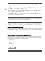
Figure 5
Attaching the Adapter to a Wall
Figure 6
Attaching the Adapter to a Wall (Alternate)
2. Attach necessary cables and/or antennas to the IAP.
3. Attach the IAP to the secured mounting adapter as shown in Figure 7.
NOTE: The W-IAP228 Instant access point does not ship with any mounting kit. The AP-220-MNT-W1 mounting kit is available as
an accessory and must be ordered separately.
AP-220_11
AP-220_14

Dell Networking W-IAP228 Wireless Instant Access Point | Installation Guide 7
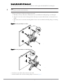
a. Align the IAP with a mounting adapter, placing the IAP so that it’s mounting tabs are at an angle of
approximately 30 degrees to the adapter.
4. Pushing toward the wall, rotate the IAP clockwise until it clicks into place (see Figure 7).
Figure 7
Attaching the IAP to the Mounting Bracket
Figure 8
Completed Installation
Grounding the IAP
After the W-IAP228 access point is mounted, it must be grounded before powering up. The grounding wire
should be #8 AWG.
1. Peel the cover of one end of the grounding wire and place the bare grounding wire into the included copper
lug, and press firmly with the crimping pliers.
2. Fasten the copper lug to the grounding hole on the IAP with the M4 x8 screw included in the IAP package, as
shown in Figure 2.

8 Dell Networking W-IAP228 Wireless Instant Access Point | Installation Guide
Connecting the Ethernet Cable
To connect the Ethernet cable to the IAP, perform the following steps using the cable glands that ships with your
IAP.
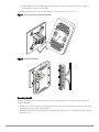
Figure 9
Installing a Cable Gland
1. Slide the sealing nut over the cable (without the RJ45 connector attached to the end).
2. Slide the clamping ring over the cable.
3. Using a crimping tool, attach the shielded RJ45 connector to the end of the cable.
4. Remove the weatherproof cap on the Ethernet port.
5. Insert the RJ45 connector to the Ethernet port.
6. Screw the clamping ring onto the Ethernet port.
7. Screw the sealing nut onto the clamping ring.
Verifying Post-Installation Connectivity
The integrated LEDs on the IAP can be used to verify that the IAP is receiving power and initializing successfully
(see Table 1 and Table 2). Refer to the Dell Networking W-Series Instant Quick Start Guide for details on
verifying post-installation network connectivity.
WARNING: Failure to use the included Ethernet cable glands can lead to connectivity and POE issues.
NOTE: The Ethernet cable is not included and must be purchased separately. Purchase a suitable UV-resistant, outdoor rated, CAT
5E or better RJ45 cable for use with the IAP.
Sealing Nut
Clamping Ring
CAT 5E or Better Cable
Seal
NOTE: The seal inside the clamping ring is applicable for cables with 5-8.5 mm diameter. In the cable gland kit, another seal is
provided for use with the cables with 7-10 mm diameter.

Dell Networking W-IAP228 Wireless Instant Access Point | Installation Guide 9
Product Specifications
Mechanical:
Device Dimensions (HxWxD): 8.7 inches x 5.9 inches x 2.6 inches (221mm x 150mm x 66mm)
Electrical
Ethernet
2 x 10/100/1000Base-T auto-sensing Ethernet RJ-45 Interfaces
MDI/MDX
Power over Ethernet (IEEE 802.3at compliant), 48VDC(nominal) /0.6A
Power
POE support on WAN port: 802.3at-compliant POE sourcing devices
Environmental
Operating
Temperature: -40ºC to 60ºC (-40ºF to 140ºF)
Humidity: 5% to 95% non-condensing
Storage
Temperature: -40ºC to 70ºC (-40ºF to 158ºF)
For additional specifications on this product, refer to the product data sheet on dell.com.

10 Dell Networking W-IAP228 Wireless Instant Access Point | Installation Guide
Safety and Regulatory Compliance
Regulatory Model Name
The regulatory model name of W-IAP228 Instant access point is APIN0228.
FCC
This device is electronically labeled and the FCC ID is displayed via the WebUI under the About menu.
FCC Class B Part 15
This device complies with Part 15 of the Federal Communications Commission (FCC) Rules. Operation is
subject to the following two conditions:
This device may not cause harmful interference.
This device must accept any interference received, including interference that may cause undesired operation.
This equipment has been tested and found to comply with the limits for a Class B digital device, pursuant to Part
15 of the FCC Rules. This equipment generates, uses and can radiate radio frequency energy and, if not installed
and used in accordance with the manufacturer’s instructions, may cause interference harmful to radio
communications.
If this equipment does cause interference, which can be determined by turning the equipment off and on, the
user is encouraged to try to correct the interference by one or more of the following measures:
Reorient or relocate the receiving antenna.
Increase the separation between the equipment and receiver.
Connect the equipment to an outlet on a circuit different from that to which the receiver is connected.
Consult the dealer or an experienced radio or TV technician for help.
EU Regulatory Conformance
Dell, hereby declares that the APIN0228 device model is in compliance with the essential
requirements and other relevant provisions of Directive 1999/5/EC -CE(!). The Declaration of Conformity made
under Directive 1999/5/EC is available for viewing on dell.com.
Proper Disposal of Dell Equipment
For the most current information about Global Environmental Compliance and Dell products, visit dell.com.
NOTE: For country specific restrictions and additional safety and regulatory information, refer to the
Dell Networking W-Series
Safety, Environmental, and Regulatory Information
document included with this product.
CAUTION: Dell access points must be installed by a professional installer. The professional installer is responsible for ensuring
that grounding is available and it meets applicable local and national electrical codes.
CAUTION: RF Radiation Exposure Statement: This equipment complies with FCC RF radiation exposure limits. This equipment
should be installed and operated with a minimum distance of 9.84 inches (25 cm) between the radiator and your body for 2.4 GHz
and 5 GHz operations. This transmitter must not be co-located or operating in conjunction with any other antenna or transmitter.
CAUTION: Changes or modifications to this unit not expressly approved by the party responsible for compliance could void the
user’s authority to operate this equipment.

Dell Networking W-IAP228 Wireless Instant Access Point | Installation Guide 11
Waste of Electrical and Electronic Equipment
Dell products at end of life are subject to separate collection and treatment in the EU
Member States, Norway, and Switzerland and therefore are marked with the symbol shown at
the left (crossed-out wheelie bin). The treatment applied at end of life of these products in
these countries shall comply with the applicable national laws of countries implementing
Directive 2002/95/EC on Waste of Electrical and Electronic Equipment (WEEE).
European Union RoHS
Aruba Networks Inc., being the manufacturer of this product, hereby declares that all CE
marked Dell wireless controller and access point products are manufactured in accordance
to the provisional requirements set forth in the RoHS Directive 2011/65/EC.
A copy of the Aruba Declaration of Conformity may be obtained upon request from:
Aruba Networks International Ltd.
Building 1000,
Citygate Mahon
Cork Ireland
Please include the regulatory model number located on the product’s regulatory nameplate with the request.
China RoHS
Dell products also comply with China environmental declaration requirements and are labeled
with the “EFUP 10” label shown at the left.
India RoHS
This product complies with RoHS requirements as prescribed by E-Waste (Management & Handling) Rules,
governed by the Ministry of Environment & Forests, Government of India.
Canadian Statement
Under Industry Canada regulations, this radio transmitter may only operate using an antenna of a type and
maximum (or lesser) gain approved for the transmitter by Industry Canada. To reduce potential radio
interference to other users, the antenna type and its gain should be so chosen that the equivalent isotropically
radiated power (e.i.r.p.) is not more than that necessary for successful communication.
10
᳝↦᳝ᆇ⠽䋼ໄᯢ
Hazardous Materials Declaration
᳝↦᳝ᆇ⠽䋼ܗ㋴(Hazardous Substance)
䚼ӊৡ⿄
(Parts)
䪙
3E
∲
+J
䬝
&G
݁Ӌ䫀
&U
⒈㘨㣃
3%%
⒈Ѡ㣃䝮
3%'(
⬉䏃ᵓ
(PCA Boards)
h
ƻƻ ƻ ƻ ƻ
ᴎẄ㒘ӊ
(Mechanical Sub-Assemblies)
h ƻƻ ƻ ƻ ƻ
ƻ˖
㸼⼎䆹᳝↦᳝ᆇ⠽䋼䆹䚼ӊ᠔᳝ഛ䋼ᴤ᭭Ёⱘ䞣ഛ
SJ/T11363-2006 ᷛޚ㾘ᅮⱘ䰤䞣㽕∖ҹϟDŽ
Indicates that the concentration of the hazardous substance in all homogeneous materials in the parts is
below the relevant threshold of the SJ/T11363-2006 standard.
h˖ 㸼⼎䆹᳝↦᳝ᆇ⠽䋼㟇ᇥ䆹䚼ӊⱘᶤϔഛ䋼ᴤ᭭Ёⱘ䞣䍙ߎ6-7ᷛޚ㾘ᅮⱘ䰤䞣㽕∖DŽ
Indicates that the concentration of the hazardous substance of at least one of all homogeneous materials
in the parts is above the relevant threshold of the SJ/T11363-2006 standard.
ᇍ䫔ଂП᮹ⱘ᠔ଂѻકᴀ㸼ᰒ⼎կᑨ䫒ⱘ⬉ᄤֵᙃѻકৃ㛑ࣙ䖭ѯ⠽䋼DŽ
This table shows where these substances may be found in the supply chain of electronic information
products, as of the date of sale of the enclosed product.
ℸᷛᖫЎ䩜ᇍ᠔⍝ঞѻકⱘ⦃ֱՓ⫼ᳳᷛᖫᶤѯ䳊䚼ӊӮ᳝ϔϾϡৠⱘ⦃ֱՓ⫼ᳳ
՟བ⬉∴ऩܗഫ䌈݊ѻકϞ
ℸ⦃ֱՓ⫼ᳳ䰤া䗖⫼ѢѻકᰃѻકݠЁ᠔㾘ᅮⱘᴵӊϟᎹ
The Environment- Friendly Use Period (EFUP) for all enclosed products and their parts are
per the symbol shown here. The Environment- Friendly Use Period is valid only when the
product is operated under the conditions defined in the product manual.

12 Dell Networking W-IAP228 Wireless Instant Access Point | Installation Guide
This device complies with Industry Canada licence-exempt RSS standard(s).
Operation is subject to the following two conditions: (1) this device may not cause interference, and (2) this
device must accept any interference, including interference that may cause undesired operation of the device.
This product complies with Canada’s ICES-003 Issue 5 Class B standard.
Ce produit est conforme à la norme ICES-003 Issue 5 classe la norme B du Canada
(i) devices operating in the 5 150-5 250 MHz is reserved only for indoor use to reduce the risk of harmful
interference to Mobile satellite systems using the same channels;
les dispositifs fonctionnant dans la bande 5 150-5 250 MHz sont réservés uniquement pour une utilisation à
l’intérieur afin de réduire les risques de brouillage préjudiciable aux systèmes de satellites mobiles utilisant les
mêmes canaux;
(ii) the maximum antenna gain permitted for devices using the bands 5 250-5 350 MHz and 5 470-5 725 MHz
shall comply with the worst limit;
le gain maximal d’antenne permis pour les dispositifs utilisant les bandes 5 250-5 350 MHz et 5 470-5 725 MHz
doit se conformer à la limite de p.i.r.e.;
(iii) the maximum antenna gain permitted (for devices using the band 5 725-5 825 MHz) must comply with the
limit of p.i.r.e. specified for the operation point to point and not point to point, as required
le gain maximal d’antenne permis (pour les dispositifs utilisant la bande 5 725-5 825 MHz) doit se conformer à la
limite de p.i.r.e. spécifiée pour l’exploitation point à point et non point à point, selon le cas.
In addition, users should be advised that users of high-speed cameras power are designated primary users (ie d.,
they have priority) for the bands 5 250-5 350 MHz and 5 650-5 850 MHz and that these radars could cause
interference and / or damage to LE-LAN devices.
De plus, les utilisateurs devraient aussi être avisés que les utilisateurs de radars de haute puissance sont désignés
utilisateurs principaux (c.-à-d., qu’ils ont la priorité) pour les bandes 5 250-5 350 MHz et 5 650-5 850 MHz et que
ces radars pourraient causer du brouillage et/ou des dommages aux dispositifs LAN-EL.
NOTE: No emissions are permitted in the band 5 600-5 650 MHz. to further notice, the devices covered by this
Annex should not be able to transmit in the band 5 600-5 650 MHz to protect radars Environment Canada
weather in this band.
NOTE: Aucune émission n’est permise dans la bande 5 600-5 650 MHz. Jusqu’à nouvel avis, les dispositifs visés par
la présente annexe ne doivent pas être en mesure d’émettre dans la bande 5 600-5 650 MHz, afin de protéger les
radars météorologiques d’Environnement Canada exploités dans cette bande.
CAUTION: RF Declaration on the radio show: This equipment complies with IC standards to RF radiation exposure limits. This
equipment must be installed and operated with a minimum distance of 7,9 inches (20 cm) between the radiator and your body for
2,4 GHz and 5 GHz operations. this transmitter must not be co-located or operating in conjunction with any other antenna or
transmitter.
CAUTION: RF Déclaration sur la radio exposition: Cet équipement est conforme aux normes IC Limites d'exposition aux
rayonnements RF. Cet équipement doit être installé et utilisé à une distance minimum de 7,9 pouces (20 cm) entre l'radiateur et
votre corps pour 2,4 GHz et 5 GHz opérations. cet émetteur ne doit pas être colocalisées ou opérant en conjonction avec une
autre antenne ou émetteur.

Dell Networking W-IAP228 Wireless Instant Access Point | Installation Guide 13
Canadian Caution
This radio transmitter (identify the device by certification number, or model number ifCategory II) has been
approved by Industry Canada to operate with the antenna typeslisted below with the maximum permissible gain
and required antenna impedance foreach antenna type indicated. Antenna types not included in this list, having
a gaingreater than the maximum gain indicated for that type, are strictly prohibited for usewith this device.
Gain of antenna: 7,4dBi for 2,4G band; 9,1dBi for 5G band;
Type of antenna: directional;
Impedance of antenna: 50ohm
Le présent émetteur radio (identifier le dispositif par son numéro de certification ouson numéro de modèle s'il
fait partie du matériel de catégorie I) a été approuvé parIndustrie Canada pour fonctionner avec les types
d'antenne énumérés ci-dessous etayant un gain admissible maximal et l'impédance requise pour chaque type
d'antenne.Les types d'antenne non inclus dans cette liste, ou dont le gain est supérieur au gain
maximal indiqué, sont strictement interdits pour l'exploitation de l'émetteur.
Gain d'antenne: 7,4dBi for 2,4G band; 9,1dBi for 5G band;
Type d'antenne: 50 ohm, directionnel.

14 Dell Networking W-IAP228 Wireless Instant Access Point | Installation Guide
This page is intentionally left blank.

Dell Networking W-IAP228 Wireless Instant Access Point | Installation Guide 15
This page is intentionally left blank.

Copyright
© 2015 Aruba Networks, Inc. Aruba Networks trademarks include , Aruba Networks
®
, Aruba Wireless Networks
®
, the registered Aruba the Mobile
Edge Company logo, and Aruba Mobility Management System
®
. Dell™, the DELL™ logo, and PowerConnect™ are trademarks of Dell Inc.
All rights reserved. Specifications in this manual are subject to change without notice.
Originated in the USA. All other trademarks are the property of their respective owners.
Open Source Code
Certain Aruba products include Open Source software code developed by third parties, including software code subject to the GNU General Public License (GPL), GNU
Lesser General Public License (LGPL), or other Open Source Licenses. The Open Source code used can be found at this site:
http://www.arubanetworks.com/open_source
Includes software from Litech Systems Design. The IF-MAP client library copyright 2011 Infoblox, Inc. All rights reserved. This product includes software developed by Lars
Fenneberg, et al.
Legal Notice
The use of Aruba Networks, Inc. switching platforms and software, by all individuals or corporations, to terminate other vendors’ VPN client devices constitutes complete
acceptance of liability by that individual or corporation for this action and indemnifies, in full, Aruba Networks, Inc. from any and all legal actions that might be taken against it
with respect to infringement of copyright on behalf of those vendors.
Dell Networking W-IAP228 Wireless Instant Access Point | Installation Guide
Part Number 0511760-01 | May 2015
Contacting Dell
Website Support
Main Website dell.com
Contact Information dell.com/contactdell
Support Website dell.com/support
Documentation Website dell.com/support/manuals
-
 1
1
-
 2
2
-
 3
3
-
 4
4
-
 5
5
-
 6
6
-
 7
7
-
 8
8
-
 9
9
-
 10
10
-
 11
11
-
 12
12
-
 13
13
-
 14
14
-
 15
15
-
 16
16


Dell W-Series 228 Access Points Le manuel du propriétaire
- Catégorie
- Points d'accès WLAN
- Taper
- Le manuel du propriétaire
dans d''autres langues
Documents connexes
-
Dell W-IAP214/215 Le manuel du propriétaire
-
-
Dell W-IAP274/275 Mode d'emploi
-
-
Dell W-Series 334/335 Access Points Le manuel du propriétaire
-
Dell W-Series 314/315 Access Points Le manuel du propriétaire
-
Dell W-Series 228 Access Points Le manuel du propriétaire
-
Dell W-IAP103 Mode d'emploi
-
-
Dell W-Series 205H Access Points Le manuel du propriétaire