Nibart 1060-56 User's Installation, Operation And Maintenance Manual
- Catégorie
- Cheminées
- Taper
- User's Installation, Operation And Maintenance Manual
Ce manuel convient également à

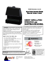
1060 Series (Jive)
Gas Fired Vented Room
Heater (Direct Vent)
USERS’ INSTALLATION
OPERATION and
MAINTENANCE MANUAL
12285 Cardinal Street
Mission, BC V4S 1L3
Canada
INSTALLER: Leave this manual with the appliance.
CONSUMER: Retain this manual for future reference.
Do not store or use gasoline or other flammable
vapors and liquids in the vicinity of this or any other
appliance.
WHAT TO DO IF YOU SMELL GAS:
Do not try to light any appliance.
Do not touch any electrical switch; do not use
any phone in your building.
Immediately call your gas supplier from a
neighbor’s phone. Follow the gas supplier’s
instructions.
If you cannot reach your gas supplier, call the fire
department.
Installation and service must be performed by a
qualified installer, service agency or the gas
supplier.
This appliance may be installed in an aftermarket
permanently located, manufactured home (USA
only) or mobile home, where not prohibited by
local codes.
This appliance is only for use with the type
of gas indicated on the rating plate. This
appliance is not convertible for use with other
gases, unless a certified kit is used.
*Conversion kit required for Propane use
WARNING: If the information in this manual is
not followed exactly, a fire or explosion may
result causing property damage, personal
injury or loss of life.
Tested and
listed by
LABTEST Certification Inc
Richmond, British Columbia
ANSI Z21.88-2009/CSA 2.33-2009

INTRODUCTION
Congratulations on choosing a Nibart Custom !
The Series 1060 is one of the most advanced Power Vented Gas Fireplace heaters available
today. It is solidly designed using the latest technology and manufactured to the highest quality.
It is our aim to provide you with an appliance for many trouble-free years of reliable service.
Some of the many features of your Series 1060 are:
Heater Classification The Series 1060 is classified as a decorative/heating
appliance.
Therefore, it uses Power Vent safety technology and it is
suitable for continuously operated zone heating.
Adjustable Flame The flame aesthetics and heat output can be adjusted to suit
the owner’s liking and heating needs (using optional flame
step valve).
Solid Construction The Series 1060 is mainly constructed of 16 gauge
galvanized and aluminized coated steel for long life and
durability.
Optional Accessories Check with your Authorized Nibart Custom Dealer for optional
accessories to suit your home’s décor and your tastes.
Electronic Control System The Series 1060 uses a gas control valve uses an
Intermittent Pilot or Standing Pilot system.
Fireplace Model Number Series 1060
Fireplace Serial Number
Date of Installation
Type of Gas Used by the Fireplace
Dealer’s Name

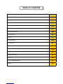
TABLE OF CONTENTS
Caution and Safety Instructions 4
Appliance Certification, Installation Codes and Specifications 5
Rating Plate 6
Appliance Dimensions 7
Framing Dimensions and Clearance to Combustibles 8-10
Gas Connections 11
Electrical Connections 12-15
Final Inspection 16
First Fire 17
Honeywell SV950 18-19
SIT Gas Valve 20
SIT Controls 21-28
Skytech Controls 29-34
Maintenance 35
Lighting Instructions 36
Parts List 38
Frequently Asked questions 39
Warranty 40

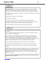
Series 1060 4
Due to high temperatures, the appliance should be located out of traffic and away from furniture
and draperies.
Children and adults should be alerted to the hazards of high surface temperature and stay
away to avoid burns or clothing ignition.
Young children should be carefully supervised when they are in the same room as the
appliance. Toddlers, young children and others may be susceptible to accidental contact
burns. A physical barrier is recommended if there are at risk individuals in the house. To
restrict access to a fireplace or stove, install an adjustable safety gate to keep toddlers, young
children and other at risk individuals out of the room and away from hot surfaces.
Clothing or other flammable material should not be placed on or near the appliance.
Do not operate with cracked or broken glass. Be careful not to strike or slam the glass.
Any safety screen or guard removed for servicing an appliance must be replaced prior to
operating.
Installation and Repair should be done by a qualified service person. The appliance should be
inspected before use and at least annually by a professional service person. More frequent
cleaning may be required due to excessive lint from carpeting, bedding materials, etc. It is
imperative that the control compartments, burners and circulating air passageways of the
appliance are kept clean.
Do not use this appliance if any part has been under water. Immediately call a qualified service
technician to inspect the appliance and to replace any part of the control system and any gas
control which has been under water.
CAUTION
FOR YOUR SAFETY - Do not install or operate your Nibart Custom Series 1060 without
reading and understanding this manual. Any installation or operational deviation from this
instruction manual voids the Nibart Custom Industries Warranty and may prove hazardous.
This appliance must be installed by a qualified gas installer and the installation must conform to
the installation codes.
Provide adequate clearance around air openings.
Never obstruct front openings.
Provide adequate clearances for proper operation and servicing of the appliance.
This appliance must be properly connected to an approved venting system and must not be
connected to a chimney flue serving a separate solid fuel burning appliance.
Must provide adequate clearance around the intake and exhaust openings
SAFETY

Series 1060 5
This appliance was listed by LABTEST Certification Inc to the following USA and Canadian gas
appliance standards.
- ANSI Z21.88-2009/CSA 2.33-2009 Vented Gas Fireplace Heaters
- CAN/CGA-2.17-M91, Gas-Fired Appliances for Use at High Altitudes
-CSA P.4.1-09 testing method for measuring annual fireplace efficiency.
The listing label is attached to the appliance on the bottom right side of the appliance.
A copy is shown on page
Please contact Archgard Industries Ltd., if you have any questions regarding the certification of
this appliance.
APPLIANCE CERTIFICATION
INSTALLATION CODES
This appliance must be installed by a qualified gas appliance installer. The installation must
conform with the local codes or, in the absence of local codes, with the current National Fuel
Gas Code ANSI Z223.1/ NFPA 54 in the US, or Installation Code CAN/CGA-B149.1 in Canada.
Electrical connections and grounding must conform with local code, or current National
Electrical code ANSI/NFPA No. 70-1987 in the US, and in Canada the current Canadian
Electrical Code CSA C22.1.
A manufactured home (USA only) or mobile home OEM installation must conform with the
Manufactured Home Construction and Safety Standard, Title 24CFR, Part 3280, or, when such
a standard is not applicable, the Standard for manufactured Home Installations, ANSI/NCSBCS
A225.1 or Standard for Gas Equipped Recreational vehicles and Mobile Housing, CSA Z240.4
We recommend that our gas hearth products be installed and serviced by professionals
who are certified in the U.S. by the National Fireplace Institute®(NFI) as NFI Gas
Specialists.
SPECIFICATIONS
/. Natural Gas (NG) Propane (LP)
Manifold Pressure 3.5 in. W.C. (0.9 kPa) 10.0 in. W.C. (2.5 kPa)
Min. Supply Press
Max Supply Press 4.5 in. W.C. (1.2 kPa)
14.0 in. W.C. (3.5 kPa) 11.0 in. W.C. (2.8 kPa)
14.0 in. W.C. (3.5 kPa)
Orifice Size Center
Orifice Size Sides See Table See Table
Nominal Input
Rating See Table See Table
Electrical Rating 120 VAC, 60Hz less than 2 A. / 120 VAC, 60Hz less than 2 A. /
Gas Control SIT SIT
Altitude 0 - 4,500 ft. (0 - 1372 M) 0 - 4,500 ft. (0 - 1372 M)
Primary Air Opening 1/16” (3 mm) OPEN 1/4” (12 mm) OPEN
HIGH ALTITUDE INSTALLATION
When installing this appliance beyond 4500 ft. (1372 M) above sea level, the appliance must
be properly de-rated and installed according to local codes, in the absence of local codes, with
the current National Fuel Gas Code, ANSI Z223.1/ NFPA 54, in the US or Installation Code,
CAN/CGA-B149, in Canada.

Series 1060 6
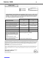
RATING PLATE
NG / NATURAL
LP / PROPANE
This appliance must be installed in accordance with local codes, if any; if none, follow the National Fuel Gas Code, ANSI Z223.1/NFPA 54, or Natural
Gas and Propane Installation Codes, CSA B149,1. Electrical connections and grounding must be in accordance with local codes, if any; if none, follow
the current CAN/CSA C22.1 in Canada and ANSI/NFPA 70 in the US. This appliance is certified for installation in a bedroom or a bed sitting room.
This appliance is only for use with the gas indicated on the rating plate and may be installed in an aftermarket, permanently located, manufactured
(mobile) home where not prohibited by local codes. See owner’s manual for details. This appliance is not convertible with other gases, unless a
certified kit is used.
FOR USE WITH GLASS DOORS CERTIFIED WITH THIS APPLIANCE ONLY.
Il faut que cet appareil soit installé selon les codes locaux, s’il y en a; sinon, suivre le CAN/CGA-B149 actuel au Canada et ANSI Z223.1 aux É.-U. Il
faut que le raccordement électrique et la mise à la masse soient en conformité avec les codes locaux, s’il y en a; sinon, suivre le CAN/CSA C22.1
actuel au Canada et ANSI/NFPA 70 aux É.-U. Cet appareil est certifié pour l’installation dans une chambre à coucher ou une pièce qui sert de
chambre.
LISTED VENTED GAS FIREPLACE HEATER and GAS-FIRED APPLIANCES FOR USE AT HIGH ALTITUDES.
RADIATEUR VENTILE, CIRCULATEUR DU TYPE VENTILATEUR. Tested to / Testée selon les normes : ANSI
Z21.88-2009 / CSA 2.33-2009 and CAN/CGA-2.17-M91 VENTED GAS FIREPLACE HEATER-NOT FOR USE WITH
SOLID FUEL. This vented gas fireplace heater is not for use with air filters. Certified for use in both CANADA and
USA. / Certifié pour utilisation dans le Canada et les ÉTATS-UNIS
DO NOT REMOVE THIS LABEL
NE PAS ENLEVER CETTE ÉTIQUETTE
# de série
Serial # LC
Made in Canada by / Fabrique au Canada par:
Nibart Designs. Mission, B.C.
100– 1060 AUGUST 2012
NG LPG
Input rating / Entrée assignée **** ****
Manifold pressure / Pression d’admission 3.5”. W.C. (0.9 kPa) 10” W.C. (2.5 kPa)
Orifice size - Center/ Dimension de l’orifice
Orifice size - Outside/ Dimension de l’orifice **** ****
Minimum supply pressure for purpose of input
adjustment / Pression minimale d’alimentation
pour le but d'ajustement de contribution 5 in. W.C. (1.24 kPa) 11.0 in. W.C. (2.8 kPa)
Control valve / La soupape contrôle: SIT SIT
Altitude / Elevation 0 - 4500 ft (0 - 1372 m) 0 - 4500 ft (0 - 1372 m)
Electrical rating / Tension électrique 120 VAC, 60 Hz, 1.4 A 120 VAC, 0.6A
Keep burner and control compartment clean. See
Instructions accompanying the heater. Maintenir
propres le brûleur et le compartiment de com-
mande. Voir les instructions relatives à l’installa-
tion et au fonctionnement qui accompagnent le
radiateur.
Optional fuel conversion kit : 57-CKLP
Clearances are measured from the edge of the
firebox door unless otherwise noted.
Minimum clearances to Combustibles / Distances:
Minimales entre l’appareil et les combustibles:
****
See Owner’s Manual for additional clearances

Series 1060 7
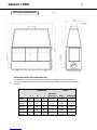
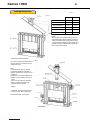
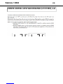
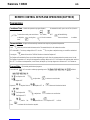
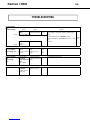
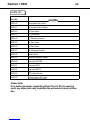
APPLIANCE DIMENSIONS
DIMENSIONS INPUT
A B C
AIR INTAKE
(Glass Front) BTU's INJECTOR #
1060-38 38” 18” 44” 2 X 4" 25,000 1 X #34
1060-44 44” 18” 50” 2 X 4" 25,000 1 X #34
1060-50 50” 18” 56” 2 X 4" 35,000 3 X #31
1060-56 56” 18” 62” 2 X 4" 40,000 3 X #29
1060-62 62” 18” 68” 2 X 4" 50,000 3 X #26
IMPORTANT NOTES ON COMBUSTION AIR:
Combustion air must be provided from other than the same pressure zone as the unit.
It is recommended that the combustion air be taken from outside, as close to the exhaust as
possible.
Figure 1
Table 1

Series 1060 8
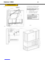
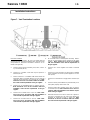
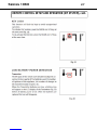
Framing Dimensions
The following section describes the require-
ments for framing for the model 1060 Series
Note: Framing should be constructed as
required by local building codes.
When installing the unit consider the following:
Consider room traffic.
Insure there is plenty of ventilation.
Do not obstruct air supply vents.
NOTE:
All design dimensions and
specifications are subject to
approval on acceptance of
signed quote.
Mantel clearances
Figure 2
Figure
Figure 4
Combustible
Surface

Series 1060 9
Framing Dimensions
Inches MM
Top - to standoffs 0” 0
Sides-to standoffs 0” 0
Adjacent Side Wall 12” 300
Floor (from opening) 0” 300
Front (from opening) 12” 300
Ceiling (from opening) 36” 900
Paints:
When painting around any fireplace it is rec-
ommended by the Master Painters and Deco-
rators Association that a quality Alkyd sealer
is applied before applying of latex paints. This
prevents leaching of water from evaporation
thus causing discoloration.
Figure 5
Table 3
Combustion Air Requirements
As a rule it requires 800-1000CFM of
fresh air to burn 10,000 Btu’s of nat-
ural/propane gas.
Note:
During the quote process we will
require the altitude of the install so
that the unit will arrive set up for your
installation.
However it is the responsibility of the
installer to check setup in his area is
correct.
Some areas for instance will down
rate the calorific value of the gas
supply to allow for altitude.
Venting
Certified ‘B’ Vent or flex pipe may be
used. See table #** for clearances.
All sealed models use 10” pipe.
Figure 5
Figure 6

Series 1060 10
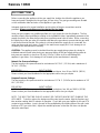
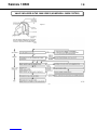
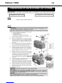
Installation Instructions
Horizontal Installation
The horizontal run must have a 1/4” rise on an exterior wall and
must meet all local and national building codes, and must not be
easily blocked or obstructed. Termination clearances are as
follows (see Figure 16):
A. Clearance above ground, verandah, porch, deck, or balco-
ny: 12” minimum (30 cm.)
B. Clearance to a window or door that may be opened: 9”
minimum (23 cm)
C. Vertical clearance to a ventilated soffit located above the
termination within a horizontal distance of 2 feet from the
centerline of the termination: 18” minimum (46 cm). Note:
Clearances are to be in accordance with local installa-
tion codes and the requirements of the gas supplier.
D. Clearance to an unventilated soffit: 12” minimum (30 cm).
Note: Clearances are to be in accordance with local
installation codes and the requirements of the gas
supplier.
E. Clearance to an outside corner: 9” (23 cm). Note: Clear-
ances are to be in accordance with local installation
codes and the requirements of the gas supplier.
F. Clearance to an inside corner: 9” (23 cm). Note: Clear-
ances are to be in accordance with local installation
codes and the requirements of the gas supplier.
G. Do not install above a meter/regulator assembly within 3
feet (90 cm) horizontally from the centerline of the meter/
regulator. Note: Clearances are to be in accordance
with local installation codes and the requirements of
the gas supplier.
H. Clearance to a service regulator vent outlet: 6’ minimum
(1.8 m)
I. Clearance to a non-mechanical air supply inlet to a building
or the combustion air inlet to any other appliance: 12” mini-
mum (30 cm)
J. Clearance to a mechanical air supply inlet: 6’ minimum (1.8
m)
K. Clearance above paved sidewalk or paved driveway locat-
ed on public property: refer to local code
L. Clearance under open verandah, porch, deck, or balcony:
12” minimum (30 cm). Note: Clearances are to be in ac-
cordance with local installation codes and the require-
ments of the gas supplier.
M. Maximum horizontal run 5’ after 2’ vertical rise. Liquid Pro-
pane gas 5’ horizontal run to 35’ vertical rise. Natural Gas
maximum 35’ horizontal run with 7’ vertical rise. Note:
Clearances are to be in accordance with local installa-
tion codes and the requirements of the gas supplier.
Figure 7 – Vent Termination Locations

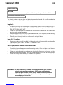
Series 1060 11
Before connecting the appliance to the gas supply line, double check that the appliance you
have purchased is designed for the gas type you are using. The gas type markings are located
on the certification label and also on the appliance’s gas valve.
Adequate clearance for proper installation and checking of the gas connections must be
provided. All gas connections must be checked for gas leaks.
GAS CONNECTIONS
Have your gas supplier or a qualified gas fitter run a gas supply line into the fireplace. The line
must be properly sized and fitted according to the installation codes. Immediately upstream of the
supply connection, the fitter shall provide an accessible manual shut-off valve. When connecting
the supply line to the gas valve, the installer shall brace the gas valve to ensure that the gas valve
is not moved from its bracket. If the valve is not braced when the supply line is connected, the
valve may be moved and cause a “break” in the main burner supply line. Such damage is not
covered by the manufacturer’s warranty.
CAUTION: The appliance must be isolated from the gas supply piping system by closing its
individual manual shutoff valve during any pressure-testing of the gas supply piping system at
test pressures equal to or less than 1/2 psig (3.5 kPa). Failure to do so will damage the
appliance’s gas valve. Such damage is not covered by the manufacturer’s warranty.
Natural Gas Pressure Settings:
The inlet supply or line pressure must be a minimum of 4.5” W.C. (1.2 kPa) and a maximum of
14” W.C. (3.5 kPa).
ELEVATION INPUT RATING
0-4500 ft (0-1372 M) 4500 ft (1372 M) and above. less 4% per 1060 ft. (305 M)
Please contact your local distributor for the appropriate orifice size you require.
Propane Pressure Settings:
The inlet supply or line pressure must be a minimum of 11” W.C. (2.8 kPa) and a maximum of 14”
W.C. (3.5 kPa).
ELEVATION INPUT RATING
0-4500 ft. (0-1372 M) 4500 ft. (1372 M) and above less 4% per 1060 ft. (305 M)
Please contact your local distributor for the appropriate orifice size you require.
NOTE: THE INPUT RATING SHOULD ALWAYS BE CHECKED WHEN FIRST RUNNING THIS
APPLIANCE. To do this, reduce the background flow rate, time the meter, light the fireplace and
take another reading after 15 minutes of operation. Check with your gas supplier for the gas BTU
content at your elevation. Input is the rate of flow multiplied by the heating value of the gas (cubic
feet/hour x BTU per cubic feet). Adjust the manifold pressure so that the unit does not operate
above the rated input.

Series 1060 12
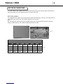
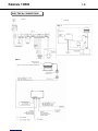
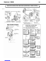
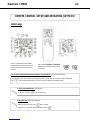
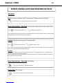
ELECTRICAL CONNECTIONS
The series 1060 comes supplied with either the Enervex ADC100 used mostly for glass fronted units or
the Enervex EBC12 used for optional quiet run for open faced units.
ADC100 system:
For full details of this system see enclosed Enervex ADC100 instructions. All units come ready wired for
site requiring only power vent and optional damper to be connected.
Note:
We can supply the unit with all controls installed into the unit or with the NB100 external control box
ready for simple hook up, this should be determined at time of order.
Figure 8
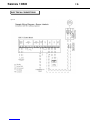
Table 4
GLASS FRONT UNITS
ENERVEX EXTERNAL POWER VENT
Model Model Volt HP Amp RPM CFM
1060-38 RS009 120 1/30 0.5 1600 450
1060-44 RS009 120 1/30 0.5 1600 450
1060-50 RS009 120 1/30 0.5 1600 450
1060-56 RS012 120 1/10 1.2 1600 950
1060-62 RS012 120 1/10 1.2 1600 950


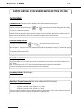
Series 1060 14
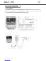
ELECTRICAL CONNECTIONS
EBC12 system:
For full details of this system see enclosed Enervex EBC12 instructions. All units come ready wired for
site requiring only power vent and optional damper to be connected.
Note:
We can supply the unit with all controls installed into the unit or with the NB100 external control box
ready for simple hook up, this should be determined at time of order.
Figure 12
Figure 13


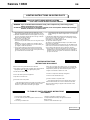
Series 1060 16
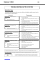
INITIAL OPERATION
1. Check that the appliance is properly vented and connected to the gas supply.
2. Check that all external parts, such as door and faceplate are properly attached and
fastened.
3. Do not operate this appliance with broken, cracked glass doors or without the door (s) in its
correct (and latched) position. Do not abuse the glass by either striking or slamming shut.
4. Check that there are no fingerprints left on glass panels, as high temperature can bake
these prints on permanently.
FINAL INSTALLATION CHECK
Each Nibart Custom Gas Fireplace is checked and tested at the factory prior to being pack-
aged and shipped to our dealers and finally installed in your home. Nibart recommends that
before leaving this unit with the customer, the installer must ensure that the appliance is firing
correctly and that the electrical system is in working order. This will include:
1. Perform leak tests of supply line, gas control valve, supply line from gas control valve and
pilot assembly.
2. Clocking the appliance to ensure the correct firing rate (see page 9 of this manual).
3. If required, adjusting the primary air to burner to ensure that the flame does not carbon or
soot.
4. Check for proper operation including correct drafting.
As a reminder, a TAG is attached to all of our gas fireplaces. This TAG is located at the gas
control valve. See Fig ?.
Any alteration to the product that causes carboning or sooting that results in any
damage or requires cleaning is not the responsibility of the manufacturer.
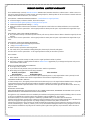
NIBART CUSTOM INDUSTRIES LTD.
*** INSTALLER ***
IMPORTANT NOTICE
ALL GAS AND ELECTRICAL CONNECTIONS
** MUST ** BE CHECKED AND TESTED AT
TIME OF INSTALLATION.
Fig ?.

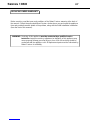
Series 1060 17
WARNING : If you do not follow these instructions exactly, a fire or explosion may
result causing property damage, personal injury or loss of life. Do not
operate the appliance with the glass front removed, cracked or broken.
Replacement of broken glass should be done by a licensed or qualified
service person.
LIGHTING INSTRUCTIONS - CAUTION
When operated for the first few times, the appliance will emit some odor and fumes. This is due
to the heat from the appliance evaporating the oils and solvents used in fabricating the
appliance. Close off the room to the rest of the house and open all windows. Keep the room
well ventilated, as smoke alarm may sound. Run the appliance for at least 6 hours at maximum
setting to allow paint to cure. Smoke and fumes caused by the curing process may cause dis-
comfort to some individuals.
FIRST FIRE
1. BEFORE LIGHTING, smell all around the appliance area for gas. Be sure to smell next
to the floor, because some gasses are heavier than air and will settle on the floor.
2. IF YOU SMELL GAS, follow the instructions as listed directly above or as shown on the
front cover of this manual.
3. Do not use this appliance if any part has been under water. Immediately call a qualified
service technician to inspect the appliance and to replace any part of the control system
and any gas control which has been under water.
4. This appliance is equipped with an ignition device which automatically lights the pilot and
main burner. The pilot and burner light automatically with the hand held remote or with
the switch on the side of the surround if it is activated.
WARNING : This appliance needs fresh air for safe operation and must be installed
so there are provisions for adequate combustion and ventilation air.
WARNING : This appliance needs fresh air for safe operation and must be installed
so there are provisions for adequate combustion and ventilation air.
Do not store or use gasoline or other flammable vapors and liquids in the vicinity of this or any
other appliance.
WHAT TO DO IF YOU SMELL GAS:
Do not try to light any appliance.
Do not touch any electrical switch; do not use any phone in your building.
Immediately call your gas supplier from a neighbor’s phone. Follow the gas supplier’s
instructions.
If you cannot reach your gas supplier, call the fire department.
Installation and service must be performed by a qualified installer, service agency or the gas
supplier.


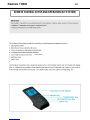
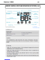
Series 1060 20
1. Remove the surround.
2. The pressure test taps are located on the valve. The taps are located in the gas valve front
face. The inlet is marked ‘IN’ and the outlet is marked ‘OUT’.
3. Loosen the set screw inside the tap with a screwdriver.
4. Connect a 1/4” (6 mm) rubber tube to the tap post and a manometer.
5. Verify that the readings obtained are within specs (as shown on the appliance rating plate)
6. Be sure to tighten the set screw inside the tap after you have finished taking pressure
readings.
7. Check for leaks.
VALVE INCLUDED IN THE 1060 SERIES (SIT SYSTEM)
CHECKING AND ADJUSTING PILOT
The flame should not have yellow tips but should engulf the
sensor. It can be adjusted by turning the screw marked “pilot”
on the control valve.
La page est en cours de chargement...
La page est en cours de chargement...
La page est en cours de chargement...
La page est en cours de chargement...
La page est en cours de chargement...
La page est en cours de chargement...
La page est en cours de chargement...
La page est en cours de chargement...
La page est en cours de chargement...
La page est en cours de chargement...
La page est en cours de chargement...
La page est en cours de chargement...
La page est en cours de chargement...
La page est en cours de chargement...
La page est en cours de chargement...
La page est en cours de chargement...
La page est en cours de chargement...
La page est en cours de chargement...
La page est en cours de chargement...
La page est en cours de chargement...
La page est en cours de chargement...
La page est en cours de chargement...
La page est en cours de chargement...
La page est en cours de chargement...
-
 1
1
-
 2
2
-
 3
3
-
 4
4
-
 5
5
-
 6
6
-
 7
7
-
 8
8
-
 9
9
-
 10
10
-
 11
11
-
 12
12
-
 13
13
-
 14
14
-
 15
15
-
 16
16
-
 17
17
-
 18
18
-
 19
19
-
 20
20
-
 21
21
-
 22
22
-
 23
23
-
 24
24
-
 25
25
-
 26
26
-
 27
27
-
 28
28
-
 29
29
-
 30
30
-
 31
31
-
 32
32
-
 33
33
-
 34
34
-
 35
35
-
 36
36
-
 37
37
-
 38
38
-
 39
39
-
 40
40
-
 41
41
-
 42
42
-
 43
43
-
 44
44


Nibart 1060-56 User's Installation, Operation And Maintenance Manual
- Catégorie
- Cheminées
- Taper
- User's Installation, Operation And Maintenance Manual
- Ce manuel convient également à
dans d''autres langues
- English: Nibart 1060-56
Autres documents
-
Continental Fireplaces CBL36NTE-1 Manuel utilisateur
-
Heat & Glo Tiara-I-B & Tiara-II-B Install Manual
-
NAPOLEON BL46NTE Le manuel du propriétaire
-
-
Lennox Elite EBCRNE-2 Installation Instructions Manual
-
Blodgett 1060 Series Manuel utilisateur
-
Blodgett 1060 Mode d'emploi
-
Superior Fireplaces DRL4000 Mode d'emploi
-
Rinnai RC98HPI Guide d'installation