Continental Fireplaces CBL36NTE-1 Manuel utilisateur
- Catégorie
- Cheminées
- Taper
- Manuel utilisateur
Ce manuel convient également à

FRENCH
PG. 23
W415-2760 / D / 04.20.21
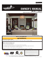
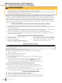
CBL36-1 / CBL46
(CBL46 with optional stainless steel surround illustrated)
- Do not store or use gasoline or other fl ammable vapors and liquids in the vicinity of this or any other appliance.
- WHAT TO DO IF YOU SMELL GAS:
• Do not try to light any appliance.
• Do not touch any electrical switch; do not use any phone in your building.
• Immediately call your gas supplier from a neighbour’s phone. Follow the gas supplier’s instructions.
• If you cannot reach your gas supplier, call the fi re department.
- Installation and service must be performed by a qualifi ed installer, service agency, or the supplier.
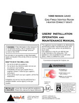
WARNING
!
ENGLISH
For indoor use only
FIRE OR EXPLOSION HAZARD
Failure to follow safety warnings exactly could result in serious injury, death, or property damage.
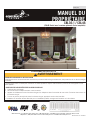
OWNER’S MANUAL
SAFETY INFORMATION
Wolf Steel Ltd., 24 Napoleon Rd., Barrie, ON, L4M 0G8 Canada / 103 Miller Drive, Crittenden, Kentucky, USA, 41030
Phone 1 (866) 820-8686 • www.continentalfi replaces.com • [email protected]

W415-2760 / D / 04.20.21
EN
2
safety information
• This appliance is hot when operated and can cause
severe burns if contacted.
• Any changes to this appliance or its control can be
dangerous and are prohibited.
• Do not operate appliance before reading and
understanding operating instructions. Failure
to operate appliance according to operating
instructions could cause fi re or injury.
• Risk of fi re or asphyxiation do not operate appliance
with fi xed glass removed.
• Do not connect 110 volts to the control valve.
• Risk of burns. The appliance should be turned off
and cooled before servicing.
• Do not install damaged, incomplete or substitute
components.
• Risk of cuts and abrasions. Wear protective gloves
and safety glasses during installation. Sheet metal
edges may be sharp.
• Children and adults should be alerted to the
hazards of high surface temperature and should
stay away to avoid burns or clothing ignition.
• Young children should be carefully supervised
when they are in the same room as the appliance.
Toddlers, young children, and others may be
susceptible to accidental contact burns. A
physical barrier is recommended if there are at
risk individuals in the house. To restrict access to
an appliance or stove, install an adjustable safety
gate to keep toddlers, young children and other at
risk individuals out of the room and away from hot
surfaces.
• Clothing or other fl ammable material should not be
placed on or near the appliance.
• Due to high temperatures, the appliance should be
located out of traffi c and away from furniture and
draperies.
• Ensure you have incorporated adequate safety
measure to protect infants/toddlers from touching
hot surfaces.
• Even after the appliance is out, the glass and/or
screen will remain hot for an extended period of
time.
• Check with your local hearth specialty dealer
for safety screens and hearth guards to protect
children from hot surfaces. These screens and
guards must be fastened to the fl oor.
• Any safety screen, guard or barrier removed for
servicing the appliance, must be replaced prior to
operating the appliance.
• The appliance is a vented gas-fi red appliance. Do
not burn wood or other materials in the appliance.
• The appliance area must be kept clear and free
from combustible materials, gasoline and other
fl ammable vapors and liquids.
!
WARNING
• Under no circumstances should this appliance be
modifi ed.
• This appliance must not be connected to a chimney
fl ue pipe serving a separate solid fuel burning
appliance.
• Do not use this appliance if any part has been
under water. Immediately call a qualifi ed service
technician to inspect the appliance and to replace
any part of the control system and any gas control
which has been under water.
• Do not operate the appliance with the glass door
removed, cracked or broken. Replacement of the
glass should be done by a licensed or qualifi ed
service person.
• Do not strike or slam shut the appliance glass door.
• When equipped with pressure relief doors, they
must be kept closed while the appliance is
operating to prevent exhaust fumes containing
carbon monoxide, from entering into the home.
Temperatures of the exhaust escaping through
these openings can also cause the surrounding
combustible materials to overheat and catch fi re.
• Only doors / optional fronts certifi ed with the unit
are to be installed on the appliance.
• Keep the packaging material out of reach of
children and dispose of the material in a safe
manner. As with all plastic bags, these are not toys
and should be kept away from children and infants.
• As with any combustion appliance, we recommend
having your appliance regularly inspected and
serviced as well as having a carbon monoxide
detector installed in the same area to defend you
and your family against carbon monoxide.
• Ensure clearances to combustibles are maintained
when building a mantel or shelves above the
appliance. Elevated temperatures on the wall or
in the air above the appliance can cause melting,
discolouration or damage to decorations, a T.V. or
other electronic components.
• A barrier designed to reduce the risk of burns from
the hot viewing glass is provided with this appliance
and shall be installed.
• If the barrier becomes damaged, the barrier shall
be replaced with the manufacturer’s barrier for this
appliance.
• Installation and repair should be done by a qualifi ed
service person. The appliance should be inspected
before use and at least annually by a professional
service person. More frequent cleaning may be
required due to excessive lint from carpeting,
bedding material, etc. It is imperative that control
compartments, burners and circulating air
passageways of the appliance be kept clean.
!
WARNING:
This product can expose you to chemicals including lead and lead compounds,
which are known to the State of California to cause cancer, and chemicals including carbon
monoxide, which are known to the State of California to cause birth defects or other reproduc-
tive harm. For more information, go to www.P65Warnings.ca.gov.

EN
W415-2760 / D / 04.20.21
3
table of contents
1.0 getting to know your appliance 5
1.1 control access 6
1.2 rating plate information 6
2.0 operating your appliance 7
2.1 using your appliance 7
2.2 on/off components 7
2.3 operating and lighting instructions 8
2.4 pilot-on-demand 9
2.4.1 changing the batteries in the battery holder 10
2.4.2 turndown 10
3.0 clearances around fireplace 11
3.1 optional heat management system 12
3.2 clearances around appliance (TV and valuable objects) 13
4.0 maintenance 14
4.1 care of glass 14
4.2 care of plated parts 15
4.3 safety barrier removal 15
4.4 door trim removal 16
4.5 fi rebox glass door removal 16
5.0 replacement parts 17
6.0 accessories 18
7.0 troubleshooting 19
8.0 warranty 20
9.0 service history 21
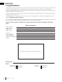
This owner’s manual is written for a complete series of fi replaces that have a variety of different features and speci-
fi cations. Before reading this manual, be sure you know which model of fi replace that you have. This information
will have been fi lled out by the installer on the following page and on the rating plate that is permanently attached
to the fi replace (see “rating plate information” section).
This manual is for the:
• CBL36-1 and CBL46 models
If required, more detailed technical information is included in the fi replace installation manual.
The information throughout this manual is believed to be correct at the time of printing. Wolf Steel Ltd. reserves
the right to change or modify any information within this manual at any time without notice. Changes, other than
editorial, are denoted by a vertical line in the margin.
Visit the Continental website for the most current version of your appliance’s manual.

W415-2760 / D / 04.20.21
EN
4
welcome
Dealer Information
Name of Dealer:
Dealer Location:
Dealer Phone:
Dealer E-mail:
Customer:
Customer Address:
Date of Installation:
Location of the appliance:
Installer:
Continental is proudly committed to your total home comfort. We are proud to say that our products continunously
surpass industry standards and our inspiration is you! More than anything, we want you to feel confi dent in
choosing Continental for your home. Our products are designed to provide that confi dence and ensure that every
Continental product is beyond compare.
Continental products are designed with superior components and materials assembled by trained craftsmen who
take great pride in their work.
A barrier designed to reduce the risk of burns from the hot viewing glass is provided with the appliance for your
safety. This barrier must be installed.
Your Continental fi replace has been thoroughly inspected by a qualifi ed technician before packaging to ensure that
you, the customer, receives the quality product that you expect from Continental.
Dealer : Fill in your dealer information (or business card) and the appliance installation information
below.
congratulations
Model:
Serial Number:
Dealer: Business card location
Natural Gas: CBL36NTE-1
CBL46NTE
Propane: CBL36PTE-1
CBL46PTE

EN
W415-2760 / D / 04.20.21
5
getting to know your appliance
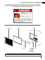
1.0 getting to know your appliance
Burner
Pilot
Safety barrier Glass door
Door trim Valve /
rating plate
/ lighting
instructions /
battery back
up
Some features and locations may vary depending on the model.
note:
HOT GLASS WILL CAUSE BURNS.
DO NOT TOUCH GLASS UNTIL
COOLED.
NEVER ALLOW CHILDREN TO
TOUCH GLASS.
!
DANGER
A barrier designed to reduce the risk of burns from
the hot viewing glass is provided with this appliance
and shall be installed for the protection of children
and other at-risk individuals.
The area above the fi replace opening including the safety barrier, barrier frame and
the surface of the wall can get very hot during operation and should never be touched
until the appliance is off and completely cooled.

W415-2760 / D / 04.20.21
EN
6
getting to know your appliance
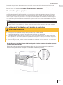
Access to the control can be done by removing the safety barrier, door trim and control cover (see “maintenance”
section for instructions on how to remove these components).
1.1 control access
FLAME
ADJUSTMENT
This illustration is for reference only. Refer to the rating plate on the appliance for accurate information.
1.2 rating plate information
The rating plate must remain with the appliance at all times. It must not be removed.
note:
Certified to Canadian and American National Standards: CSA 2.22-XXXX / ANSI Z21.50-XXXX for Vented Decorative Gas Appliances
Certifié selon les normes Nationales Canadiennes et Américaines: CSA 2.22-XXXX / ANSI Z21.50-XXXX pour les Appareils à gaz décoratif à évacuation
Direct vent, vented gas fireplaces. Approved for bedroom, bathroom and bed-sitting room installation. Suitable for mobile home installation, if installed in accordance with the current
standard CAN / CSA Z240MH Series gas equipped mobile homes in Canada, or, in the United States, the Manufactured Home Construction and Safety Standard, Title 24 CFR, Part
3280. When this US Standard is not applicable, use the Standard for Fire Safety Criteria for Manufactured Home Installations, Sites and Communities, ANSI / NFPA 501A. This appliance
must be installed in accordance with local codes, if any; if none, follow the current ANSI Z223.1 or CSA B149. For use with barrier WXXX-XXXX. Follow installation instructions.
Foyer à gaz ventilé. Homologué pour installation dans une chambre à coucher, une salle de bain et un studio. Approprié pour installation dans une maison mobile si son installation
conforme aux exigences de la norme CAN / CSA Z240MH Séries de maisons mobile équipées au gaz en vigueur au Canada, ou, aux États-Unis selon la norme 24 CFR, Part 3280,
Manufactured Home Construction and Safety Standard. Dans le cas ou cette norme d’États-Unis n’est pas pertinentes, utiliser la norme NFPA 501A, Fire Safety Criteria for Manufactured
Home Installations, Sites and Communities. Installer l’appareil selon les codes ou règlements locaux ou, en l’absence de tels règlements, selon les codes d’installation ANSI Z223.1 ou
CSA B149 en vigueur. Utiliser uniquement avec l’écran WXXX-XXXX. Suivre les instructions d’installation.
9700539 (WSL) 4001658 (NAC) 4001657 (NGZ) 4001659 (WUSA)
WOLF STEEL LTD. 24 Napoleon Road, Barrie, ON, L4M 0G8 Canada
XXXX XXXX XXXX XXXX
MODEL / MODÈLE
Altitude
Input
Reduced Input
P4
Élévation
Alimentation
Alimentation Réduite
P4
Manifold Pressure: 3.5” w.c. (NG)
Minimum Supply Pressure: 4.5” w.c. (NG)
Maximum Supply Pressure: 7”* w.c. (NG)
Pression au Collecteur: 3,5” d’une colonne d’eau (GN)
Pression d’Alimentation Min.: 4,5” d’une colonne d’eau (GN)
Pression d’Alimentation Max.: 7” ** d’une colonne d’eau (GN)
** Maximum inlet pressure not to exceed 13”.
Manifold Pressure: 10” w.c. (P)
Minimum Supply Pressure: 11” w.c. (P)
Maximum Supply Pressure: 13”* w.c. (P)
Pression au Collecteur: 10” d’une colonne d’eau (P)
Pression d’Alimentation Min.: 11” d’une colonne d’eau (P)
Pression d’Alimentation Max.: 13” * d’une colonne d’eau (P)
** Pression d’alimentation maximale ne devait pas dépasser 13”.
0-XXXXft (0-XXXXm)
Minimum clearance to combustible materials:
Top, sides & back: per standoff spacers for framing and finishing
materials. For non-combustible framing and finishing materials,
see installation manual.
Top X”
Floor X”
Sides X”
Back X”
Vent top X”
Vent sides & bottom X”
Recessed depth X”
*** Mantel X” from appliance opening
Dégagements minimaux des matériaux combustibles:
Dessus, côtés et arrière: selon les espaceurs de dégagements
pour les matériaux d’ossature selon le manuel du propriétaire
pour les matériaux de finition.
Dessus X”
Plancher X“
Côtés X”
Arrière X“
Dessus du conduit d’évent X”
Côtés et dessous du conduit d’évent X”
Profondeur d’encastré une face X”
*** Tablette X” de l’ouverture de l’appareil
WARNING
:
Do not add any material to the appliance which will come in contact with the
flames, other than that supplied by the manufacturer with the appliance.
AVERTISSEMENT
:
N’ajoutez pas à cet appareil aucun matériau devant entretien
contact avec les flammes autre que celui qui est fourni avec cet appareil par le fabricant.
*** Maximum horizontal extension:
X”. See installation manual for
greater extensions, minimum vent
lengths and maximum vent lengths.
*** L’extension horizontale maximale: X”.
Référez au manuel d’installation pour des
extensions plus grandes, les longueurs
d’évacuation minimaux et maximum.
The appliance must be vented using the appropriate Napoleon vent kits. See installation
manual for venting specifications. Proper reinstallation and resealing is necessary after servicing
the vent-air intake system.
L’appareil doit être ventilé à l’aide de l’ensemble d’évacuation propre à Napoleon. Référez au
manuel d’installation pour les spécifications d’évacuation. Il est nécessaire de bien réinstaller et
resceller l’évacuation après avoir executer l’entretien du système de prise d’air.
Serial Number / N° de Série:
W385-XXXX
REFERENCE# 161746
XXXX
VENTED DECORATIVE GAS APPLIANCE: NOT A SOURCE OF
HEAT, NOT INTENDED FOR USE AS A HEATING
APPLIANCE, NOT FOR USE WITH SOLID FUEL.
APPAREIL À GAZ DÉCORATIF À ÉVACUATION: N’EST PAS
UNE SOURCE DE CHALEUR; N’EST PAS DESTINÉ À ÈTRE
UTILISÉ COMME UN APPAREIL DE CHAUFFAGE; NE
CONVIENT PAS AUX COMBUSTIBLES SOLIDES.
FOR USE WITH GLASS DOORS CERTIFIED WITH THIS APPLIANCE ONLY.
POUR UTILISATION UNIQUEMENT AVEC LES PORTES EN VERRE
CERTIFIÉES AVEC L’APPAREIL.
XX,XXX XX,XXX
XX,XXX XX,XXX
For natural gas when equipped with No. XX drill size orifice.
For propane when equipped with No. XX drill size orifice.
Convient au gaz naturel quand l’appareil est muni d’un injecteur de diamètre no. XX.
Convient au propane quand l’appareil est muni d’un injecteur de diamètre no. XX.
Electrical rating: 115V, 60HZ. Less than 12 amperes.
Spécifications électriques: 115V, 60HZ. Moins de 12 ampère.
XX.X% XX.X%
XXXX XXXX XXXX XXXX
CERTIFIED UNDER / HOMOLOGUE SELON LES NORMES: CSA 2.33b
- 2008, ANSI Z21.88
b
- 2008 VENTED GAS FIREPLACE HEATER / APPAREIL DE CHAUFFAGE ALIMENTÉ
AU GAZ ET VENTILÉ
VENTED GAS FIREPLACE HEATER. APPROVED FOR BEDROOM, BATHROOM AND BED-SITTING ROOM INSTALLATION. SUITABLE FOR MOBILE HOME INSTALL
ATION IF INSTALLED IN ACCOR
DANCE WITH THE
CURRENT STANDARD CAN/CSA Z240MH SERIES GAS EQUIPPED MOBILE HOMES, IN CANADA OR IN THE UNITED STATES THE MANUFACTURED HOME CONST
RUCTION AND SAFETY STANDARD, TITLE 24 CFR,
PART 3280. WHEN THIS US STANDARD IS NOT APPLICABLE USE THE STANDARD FOR FIRE SAFETY CRITERIA FOR MANUFACTURED HOME INSTALLATION
S, SITES AND COMMUNITIES, ANSI / NFPA 501A.
FOYER DE CHAUFFAGE AU GAZ AVEC ÉVACUATION. HOMOLOGUÉ POUR INSTALLATION DANS UNE CHAMBRE À COUCHER, UNE SALLE DE BAIN ET UN STUD
IO. APPROPRIÉ POUR INSTALLATION DANS UNE
MAISON MOBILE SI SON INSTALLATION CONFORME AUX EXIGENCES DE LA NORME CAN/CSA Z240MH SÉRIE DE MAISONS MOBILES ÉQUIPÉES AU GAZ, E
N VIGUEUR AU CANADA OU AUX ÉTATS-UNIS DE LA
NORME DE SECURITÉ ET DE C
ONSTRUCTION DE MAISONS MANUFACTURÉES, TITRE 24 CFR,
SECTION 3280. DANS LE CAS OU CETTE NORME D'ÉTATS-UNIS NE PEUT ÊTRE APPLIQUÉE, SE RÉFÉRER A LA NORME
RELATIVE AU CRITÈRE DE MESURES DE SÉCURITÉ CONTRE L'INCENDIE POUR LES INSTALLATIONS DANS LES MAISONS MANUFACTURÉS, LES SITES ET
LES COMMUNAUTÉS, ANSI/NFPA 501A.
NOT FOR USE WITH
SOLID FUEL. FOR USE
WITH GLASS DOORS
CERTIFIED WITH THIS
UNIT ONLY.
WARNING
:
DO NOT ADD ANY MATERIAL
TO THE APPLIANCE, WHICH WILL COME
IN CONTACT WITH THE FLAMES, OTHER
THAN THAT SUPPLIED BY THE
MANUFACTURER WITH THE APPLIANCE.
MINIMUM CLEARANCE TO
COMBUSTIBLE MATERIALS:
TOP 0”
FLOOR 0”
RECESSED DEPTH ONE SIDED 23"
RECESSED DEPTH SEE THRU 13.5”
FRAMING (NOT INCLUDING
FACE MATERIAL)
SIDES 0”
VENT 2"
BACK 0”
MANTLE 15" *
TOP, SIDES & BACK: PER STAND OFF SPACERS FOR FRAMING MATERIALS. FOR FINISHING MATERIALS
SEE OWNERS MANUAL
UN COMBUSTIBLE SOLIDE NE
DOIT PAS ÊTRÉ UTILISÉ AVEC
CET APPAREIL. UTILISER AVEC
LES PORTES VITRÉES
HOMOLOGUÉES SEULEMENT
AVEC CETTE UNITÉ.
AVERTISSEMENT:
N'AJOUTEZ PAS A
CET APPAREIL AUCUN MATÉRIAU DEVANT
ENTRER EN CONTACT AVEC LES FLAMMES
AUTRE QUE CELUI QUI EST FOURNI AVEC
CET APPA
REIL PAR LE FABRICANT.
DÉGAGEMENTS
MINIMAUX DES
MATÉRIAUX COMBUSTIBLES:
DESSUS 0”
PROFONDEUR D'ENCASTRÉ 25"
PLANCHER 0”
ÉVENT 2"
CÔTES 0”
MANTEAU 15" *
ARRIÉRE 0”
MADE IN CANADA / FABRIQUÉ AU CANADA
WOLF STEEL LTD. BARRIE, ONTARIO, CANADA
ALTITUDE / ÉLÉVATION
INPUT / ALIMENTATION
REDUCED INPUT / ALIMENTATION RÉDUITE
ORIFICE / INJECTEUR
MANIFOLD PRESSURE /
PRESSION AU COLLECTEUR
MINIMUM SUPPLY PRESSURE /
PRESSION D'ALIMENTATION MINIMALE
MAXIMUM SUPPLY PRESSURE /
PRESSION D'ALIMENTATION MAXIMALE
0-4500FT (0-1370M)
30,000 BTU/H
2
3,000 BTU/H
#38
3.5" WATER COLUMN/D'UNE COLONNE D'EAU
4.5" WATER COLUMN/D'UNE COLONNE D'EAU
7.0" WATER COLUMN/D'UNE COLONNE D'EAU
0-4500FT (0-1370M)
30,000 BTU/H
23,000 BTU/H
#53
10" WATER COLUMN/D'UNE COLONNE D'EAU
11" WATER COLUMN/D'UNE COLONNE D'EAU
13" WATER COLUMN/ D'UNE COLONNE D'EAU
THE APPLIANCE MUST BE VENTED USING THE APPROPRIATE
NAPOLEON VENT KITS. SEE OWNERS INSTALLATION MANUAL
FOR VENTING SPECIFICS. PROPER REINSTALLATION AND
RESEALING IS NECESSARY AFTER SERVICING THE VENT-AIR
INTAKE SYSTEM.
L'APPAREIL DOIT ÉVACUER SES GAZ EN UTILISANT L'ENSEMBLE
D'ÉVACUATION PROPRE A NAPOLEON. RÉFÉRER AU MANUEL
D'INSTALLATION DE PROPRIÉTAIRE POUR L'ÉVACUATION
PRÉCISE. IL EST IMPORTANT DE BIEN RÉINSTALLER ET
RESCELLER L'ÉVENT APRÈS AVOIR ASSURÉ LE MAINTIEN DU
SYSTÉME DE PRISE D'AIR.
CLASSIFICATION: 115V 0.82AMP, 60HZ
W385-2007
MODEL NATURAL GAS /
GAZ NATURAL
LHD50NT
MODEL PROPANE
LHD50PT
SERIAL NUMBER/NO. DE SÉRIE:
LV50
ELECTRICAL RATING: 115V 0.82AMP, 60HZ
REFERENCE #
W/N 16131
* MAXIMUM HORIZONTAL EXTENSION / L'EXTENSION
HORIZONTALE MAXIMALE: 2". SEE INSTRUCTION MANUAL FOR GREATER EXTENSIONS.
SEE OWNER'S INSTRUCTION MANUAL FOR MINIMUM AND MAXIMUM VENT LENGTHS.
DESSUS, COTÉS & ARRIÈRE: SELON LES ESPACEURS DE DÉGAGEMENT POUR LES MATÉRIAUX D'OSSATURE
SELON LE MANUEL DE PROPRIÉTAIRE POUR LES MATÉRIAUX DE FINITION.
*
L'EXTENSION HORIZONTALE MAXIMALE: 2". RÉFÉRER AU MANUEL D'INSTRUCTION POUR DES EXTENSIONS
PLUS GRANDES. RÉFÉRER AU MANUEL D'INSTALLATION DE PROPRIÉTA
I
RE.
SAMPLE
SAMPLE
S
Appliances
eils à gaz décoratif à évacuationacuation
installed in accordance with the current nstalled in accordance with the current
ion and Safety Standard, Title 24 CFR, Part on and Safety Standard, Title 24 CFR, Part
d CommunitiesCommunities
,
ANSI / NFPA 501A. This appliance
, ANSI / NFPA 501A. This appliance
r WXXX-XXXX. Follow installation instructions.X-XXXX. Follo
stallation dans une maison mobile si son installation une maison m
, ou, aux Étatu, aux Éta
s
-
U
n
is
selo
n
la
n
o
rm
e
s selon la norm
2
4
C
FR, Part 3280,
80,
tiliser la norme iser la norme
NFPA 501A, Fire Safety Criteria for Manufacture
d
NFPA 501A, Fire Safety Criteria for Manufactured
de tels règlements, selon les codes d’installation ANSI Z223.1 ou e tels règlements, selon les codes d’installation ANSI Z223.1 ou
USA)SA)
WO
LF
S
TEEL LTD.
WOLF STEEL LTD.
24 Napoleon Road, Barrie24 Napoleon Road, Barr
XXXXXXXX
M
É
l
é
v
a
ti
o
n
Élévation
Ali
m
e
nt
a
t
ionmentation
Alim
e
nt
a
ti
o
n R
édu
it
eAlimentation Réduite
P4P4
N)
Ma
n
ifold
P
r
essu
r
e
:
Manifold Pressure:
1
0” w.c.
(
P
)(P)
M
inimum
S
u
pp
l
y
Pressure:
m Supply Pressure:
1
1” w.c.
(
P
)11” w.c. (P)
M
aximum Su
pp
l
y
Pressure:
Supply Pressure:
1
3”* w.c.
(
P
)13”* w
Pression au
C
ollecteur:
Pression au Collecteur:
1
0” d’une colonne d’eau (P)
10” d’une colonne d’eau
P
r
ess
i
o
n
d
’Alim
e
nt
a
ti
o
n Min.:
Pression d’Alimentation Min.:
1
1” d’une colonne d’eau
(
P
)11” d’une colonne d’eau (P
P
ress
i
on
d’Ali
mentat
i
on
M
ax.:
ession d’Alimentation Max.
13” * d’une colonne d’eau (P)3” * d’une colonne d’eau (P
** Pression d’alimentation maximale ne devait pas dépasser 1ssion d’alimentation maximale ne devait pas dépasser
and finishing
ing materials, ng materia
ppliance openingppliance opening
Dégagements minimaux des matériaux combustgagements minimaux des matériaux
Dessus, côtés et arrière: selon les espaceurs de dégacôtés et arrière: selon les espaceurs de
pour les matériaux d’ossature selon le manuel duatériaux d’ossature selon le manuel
pour les matéles ma
CôtéCô
Maximum horizontal extension: aximum horizontal extensio
”. See installation manual for See installation manual fo
greater extensions, minimum vent
reater extensions, minimum vent
lengths and maximum vent lengths.
engths and maximum vent lengths.
VENTED DECORATIVE GAS APENTED DECORATIVE GAS AP
HEAT, NOT INTT, NOT IN
APPLIANCIAN
APPAREIL À GAZ DAPP
UNE SOURCE
UTILIS
FOR UFOR U
X
XXX
Electrical ratin
g
: 115V, 60HZ. Less than 12 amperes.
Electrical rating: 115V, 60HZ. Less than 12 ampere
X.X%
XXXXXXXX
M
VALVE

EN
W415-2760 / D / 04.20.21
7
operating your appliance
2.0 operating your appliance
To turn the appliance on:
When operating your appliance for the fi rst time, there is a required burn-in process that cures materials used
to manufacture the fi replace that may emit both vapors and an odor. These are normal when operating a new
appliance for the fi rst time. Ensure adequate air circulation is provided during burn-in process,
2.1 using your appliance
A. Turn the on/off switch on.
B. After 3-5 seconds, the control will start a spark at the pilot, light the pilot and then the burner. The spark
period will last 60 seconds, or until the pilot has lit.
C. When used for the fi rst time, if the burn-in process was not completed by the installer, run appliance
continuously for 4 hours (burn-in).
D. Turn the appliance off. Wait until appliance is completely cool before moving to the next step.
E. Remove the safety barrier and fi rebox glass door. Clean fi rebox glass door (see “maintenance” section).
Replace fi rebox glass door and safety barrier.
For more detailed information, see your installation manual or contact your authorized dealer.
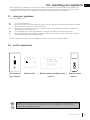
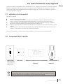
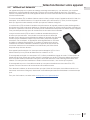
2.2 on/off components
Batteries must be disposed of according to the local laws and regulations. Some batteries may be
recycled, and may be accepted for disposal at your local recycling center. Check with your
municipality for recycling instructions.
| On/off switch | Battery holder | Battery holder (including switch) | Remote control
|
(Optional)
(Optional)
(Not supplied)

W415-2760 / D / 04.20.21
EN
8
operating your appliance
!
WARNING
• Do not turn on if children or other at risk individuals are near the appliance.
• This appliance is equipped with an ignition device which automatically lights the pilot. Do not try to light the
pilot by hand.
• Before operating, smell all around the appliance area for gas and next to the fl oor because some gas is
heavier than air and will settle on the fl oor.
• Do not use this appliance if any part has been under water. Immediately call a qualifi ed service technician
to inspect the appliance and replace any part of the control system and any gas control which has been
underwater.
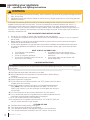
FOR YOUR SAFETY READ BEFORE LIGHTING
WHAT TO DO IF YOU SMELL GAS
LIGHTING INSTRUCTIONS
TO TURN OFF GAS
A. Stop! Read the above safety information on this label.
B. Remove batteries from the transmitter and set thermostat to lowest setting, if
equipped.
C. Turn off all electrical power to the appliance.
D. Open the glass door, if equipped.
E. Turn the manual shut-off valve clockwise to the “OFF” position. (Shut-off valve is
located on the fl ex connector).
F. Wait fi ve (5) minutes to clear out any gas. If you smell gas including near the
fl oor, STOP! Follow the instructions above in the “WHAT TO DO IF YOU
SMELL GAS” section. If you don’t smell gas; close the glass door and go to
the next step.
G. Turn the manual shut-off valve counter clockwise to the “ON” position.
H. Turn on all electrical power to the appliance and re-install the batteries into the
transmitter. Set thermostat to desired setting, if equipped.
I. Turn on the remote wall switch to the appliance.
J. If the appliance will not operate, follow instructions “TO TURN OFF GAS” and
call your service technician or gas supplier.
A. Set thermostat to lowest setting, if equipped.
B. Turn off the remote wall switch to the appliance.
C. Turn off all electric power to the appliance if service is to be performed.
D. Turn manual shutoff valve clockwise to the “OFF” positon. Do not force.
• Turn off all gas to the appliance.
• Open windows.
• Do not try to light any appliance.
• Do not touch any electric switch; do not use
any phone in your building
• Immediately call your gas supplier from a
neighbour’s phone. Follow the gas supplier’s
instructions.
• If you cannot reach your gas supplier, call
the fi re department.
• If you do not follow these instructions exactly, a fi re or explosion may result causing property damage, personal
injury, or loss of life.
• If applicable, always light the pilot whether for the fi rst time or if the gas supply has run out with the glass door
opened or removed.
add gas knob
add gas valve
Ensure that a continuous gas fl ow is at the burner before installing the door. When lit for the fi rst time, the
appliance will emit an odor for a few hours. This is a normal temporary condition caused by the “burn-in” of
paints and lubricants used in the manufacturing process and will not occur again. After extended periods of
non-operation, such as, following a vacation or warm weather season, the appliance may emit a slight odor for a
few hours. This is caused by dust particules in the heat exchanger burning off. In both cases, open a window to
suffi ciently ventilate the room.
This appliance is equipped with an ignition device which automatically lights the pilot. Do not try to light the
pilot by hand.
note:
2.3 operating and lighting instructions

EN
W415-2760 / D / 04.20.21
9
operating your appliance
This appliance is equipped with an “On Demand” intermittent pilot ignition system (IPI) which also includes a
continuous pilot ignition (CPI) mode with an integrated seven day timer. This system minimizes your appliance’s
carbon footprint as well as reducing its annual fuel consumption and operating costs.
In IPI mode, the pilot will ignite prior to the main burner, when the appliance is turned on using a switch, remote
or from a call for heat with the thermostat (if equipped). Once the appliance is turned off (or the call for heat is
satisfi ed), the main burner and pilot fl ame will shut down.
The continuous (CPI) mode is intended to enhance the performance of the appliance during the startup phase in
colder climates and extreme weather by keeping the system warm when the main burner is not in use. However,
the timer feature provides the convenience that the appliance automatically switches off the pilot when the
appliance has not been used for seven days to save unnecessary fuel consumption.
When the CPI function is turned on, the pilot will remain on after the main burner
is turned off. A timer will then begin the countdown for approximately seven days
before shutting off the pilot if the appliance is not used. This countdown will reset
anytime the appliance main burner is used. Therefore, if the appliance is regularly
used day to day, the pilot will remain on. However, this system does not require
the user to remember to turn the pilot off as summer approaches and avoids
unnecessary fuel consumption while still readily turned back on when the cold
weather returns.
Your appliance may be equipped with an ACS or remote control device which
enables you to select IPI or CPI modes.
If your appliance is equipped with an ACS switch, it has the option to change
modes. If installed with the blue wire facing up, fl ipping the switch UP turns on the
continuous pilot with timer and fl ipping the switch DOWN turns on the intermittent
pilot ignition. If installed with the white wire facing up, the opposite is true.
If your appliance is equipped with a remote control device capable of selecting IPI / CPI modes, refer to remote
operating instructions.
In order to start your pilot, turning the main burner on with the switch, remote or thermostat and then turning it off
will reactivate the continuous pilot mode and reset the seven day timer.
For further information, refer to www.napoleon.com/pilotondemand.
ADD TITLE: PIL
O
T-
O
N-DEMAND
2.4 pilot-on-demand

W415-2760 / D / 04.20.21
EN
10
operating your appliance
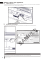
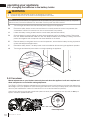
2.4.1 changing the batteries in the battery holder
• Ensure the gas and electrical power to the appliance is turned off.
• Appliance may be hot, do not service until the appliance has cooled.
!
WARNING
A. Turn off the gas and disconnect the electrical power supply from the appliance.
B. Remove the safety barrier, control cover and door trim to easily access the control compartment (see
“maintenance” section for instructions on how to remove these components).
C. Locate the battery housing located near the control board (see illustration below).
D. Open the battery housing by sliding the back piece upwards and off of the battery housing. Remove the
four “AA” alkaline batteries and install four new “AA” alkaline batteries into the battery housing. Ensure the
positive and negative ends correspond with those identifi ed on the holder.
E. Place the battery housing back into the control compartment, ensure that the battery housing is placed in
a clean and easily accessible location.
F. Reinstall the safety barrier. The safety barrier must be installed at all times during the appliance operation.
G. Turn the gas and electrical power back on to begin operating the appliance.
In the event of a power failure, your appliance can be operated using the supplied battery back-up. If a power
failure occured, remove the batteries from the holder once the power has been restored.
note:
Control module
Battery housing
Red wire
Black wire
Manual adjustments to your fi replace must only be made when the appliance is off and complete cool.
Allow safety barrier to cool before making adjustment.
The CBL36-1/CBL46 models are equipped with a manual gas control knob (located on the valve) that adjusts the
fl ame height to suit your preference. To access the gas control knob, remove your safety barrier, control cover and
door trim (see “maintenance” section for instructions on how to remove these components).
Use only your hand to turn the gas control knob (never use tools). If the knob will not turn by hand, do not try to
repair it. Contact a qualifi ed technician.
L
O
H
I
Flame adjustment
2.4.2 turndown

EN
W415-2760 / D / 04.20.21
11
clearances around fi replace
!
WARNING
• Your appliance, gas/electrical connections, venting and various key components are hidden behind the wall. It is
critical that no screws penetrate these components. Failure to follow instructions may cause improper operation,
damage, personal injury or fi re. Always use a stud fi nder and only screw into studs.
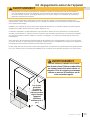
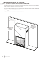
3.0 clearances around fi replace
Without making adequate provisions to account for the heat, the temperatures above the fi replace will be hot,
making it unsuitable for mounting a TV or other objects sensitive to heat without risk of damage.
Installing a mantel between this appliance and electronics or other materials that may be sensitive to heat will
reduce the effect of direct heat on them.
The size and material of the mantel will affect the allowable clearance above your fi replace. Incorrect placement
could become a fi re hazard. Consult your installation manual and/or authorized dealer for more information before
mounting a mantel, a shelf or any other object above your appliance.
Your fi replace, gas/electrical connections and vent are hidden directly behind the fi nished wall. Great care should
be taken to avoid screwing or nailing into these components. Always use a stud fi nder to determine stud location
and only screw into studs.
Do not screw into the area around the fi replace opening as some of your appliance may be hidden behind the
fi nished wall. Refer to your installation manual and/or contact your local dealer for more information.
Fireplaces
generate radiant
heat. Do not put
objects in front
of the appliance
(minimum
distance of 4 feet
[1.21m]).
The area above a fi replace gets hot.
Combustible objects or materials must
never be placed in this area. For mini-
mum clearances, refer to installation
manual or your authorized dealer.
!
WARNING

W415-2760 / D / 04.20.21
EN
12
clearances around fi replace
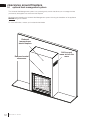
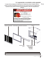
3.1 optional heat management system
The Universal Heat Management system is an optional gravity vent kit that allows you to manage the heat
produced by the appliance at and around the fi replace.
We recommend installing the Universal Heat Management system kit during the installation of the appliance
BEFORE the gas is installed.
For more information, contact your local authorized dealer.
Reduced mantel
clearances
Grill to expel
warm air into the
room
Reduced
temperatures
above fireplace

EN
W415-2760 / D / 04.20.21
13
clearances around fi replace
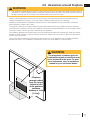
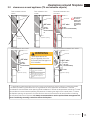
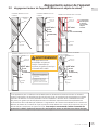
3.2 clearances around appliance (TV and valuable objects)
* TV applications were tested with the minimum enclosure dimensions and the maximum recess permissible.
This data is provided in good faith and is not a guarantee for every application and television. Care and
consideration should be taken when planning these installations to ensure the temperatures around the TV meet
all manufacturer’s recommended operating temperatures. Increasing the height of the mantel and/or TV above
the fi replace opening, the protrusion of mantel and the volume of the enclosure all have the effect of reducing
the temperature above the fi replace. It is always recommended to use the optional heat management kit
when considering mounting a television above the fi replace.
6” min.
Appliance opening
2.5” min.*
2” min.
(3” max.
recommended)
6” min.
2.5” min.*
Enclosure
Enclosure
TV bracket
TV bracket
Flush installation with
mantel
Recessed installation with
protrusion
Appliance opening
2” min.
(3” max. recommended)
Appliance
opening
Enclosure
TV bracket
Flush installation without
mantel
Appliance
Appliance
Appliance
The volume of
air must be
added to the
enclosure to
accomodate
the recessed
area.
6” min.
Enclosure
TV bracket
Partially recessed installation with mantel
Appliance opening
Appliance
Enclosure
A
3” min.
A
See “minimum clearance to
mantle” section (installation
manual).
B
Mantle clearances reduced
from opening with the use of the
universal heat management
system.
12”
max.
2.5” min.*
2” min.
(3” max.
recommended)
6” min.
Appliance opening
2.5” min.*
2” min.
(3” max.
recommended)
Enclosure
TV bracket
Flush installation with mantel
Enclosure
Appliance
B
These applications are
only acceptable when the
Universal Heat Management
kit is installed.
!
WARNING

W415-2760 / D / 04.20.21
EN
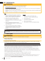
14
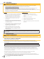
maintenance4.0 maintenance
!
WARNING
• Turn off the gas and electrical power before servicing the appliance.
• Appliance may be hot. Do not service until appliance has cooled.
For qualifi ed technicians only:
• Label all wires prior to disconnection when servicing controls. Wiring errors can cause improper and dangerous
operation. Verify proper operation after servicing.
• This appliance and its venting system should be inspected before use and at least annually by a qualifi ed service
person.
• The fl ow of combustion and ventilation air must not be obstructed.
DOS
• Clean your safety barrier regularly to prevent the
build up of excessive lint/dust from carpeting, pet
hair, etc. Vacuum using the brush attachment.
• Always use ammonia-free glass cleaners.
• Service your appliance annually and/or as
required. Service must be conducted by a qualifi ed
technician.
• Keep your appliance area clear and free of
combustible materials, gasoline, or other fl ammable
vapors and liquids.
• Check to see that the burner ignites completely
on all openings when turned on. A 5 to 10 second
total light-up period is satisfactory. Service as
required.
DON’TS
• Attempt to service the electrical or gas
components. Contact a qualifi ed technician.
• Use excessive force.
• Use abrasive cleaners on glass.
• Paint the pilot assembly.
• Place objects too close to the fi replace opening.
For any questions and/or concerns regarding your appliance, maintenance and service, please contact your
authorized dealer.
note:
Buff lightly with a clean dry soft cloth to remove accumulated dust or fi ngerprints. Clean both sides of the glass
after the fi rst 10 hours of operation with an ammonia-free glass cleaner.
Thereafter, clean as required. If the glass is not kept clean permanent discoloration and / or blemishes may
result. Contact you local authorized dealer / distributor for complete cleaning instructions.
Razor blades, steel wool, or other metallic objects must not be used on both surfaces of the glass. Doing so
can remove a thin layer of metal from the razor blades, steel wool, or other metallic objects that may then be
deposited onto the coating. This can result in a discoloured stain or scratch-like mark. More importantly, this can
scratch the glass surface, thereby reducing its strength.
Do not operate the appliance with broken glass, as leakage of fl ue gases may result.
Contact your local authorized dealer / distributor for complete cleaning instructions.
If the glass should ever crack or break while the fi re is burning, do not open the door until the fi re is out. Do not
operate the appliance until the glass has been replaced. Contact you local authorized dealer / distributor for
replacement parts. DO NOT SUBSTITUTE MATERIALS.
Vinegar-based glass cleaners have demonstrated an ability to provide a clean, streak free glass surface.
note:
Firebox Glass Door :
4.1 care of glass
!
WARNING
• Do not clean glass when hot! Do not use abrasive cleaners to clean glass.
4
Do not use ammonia-based cleaners.

EN
W415-2760 / D / 04.20.21
15
maintenance
This appliance is factory equipped with tempered glass. Use only replacement parts as supplied by the appliance
manufacturer. DO NOT SUBSTITUTE MATERIALS.
Replacement glass/frame assembly shall be replaced as a complete unit as supplied by the appliance
manufacturer.
4.2 care of plated parts
If the appliance is equipped with plated parts, you must clean fi ngerprints or other marks from the plated surfaces
before operating the appliance for the fi rst time. Use an ammonia-free or vinegar-based cleaner and a towel
to clean. If not cleaned properly before operating for the fi rst time, the marks can cause permanent blemishes
on the plating. After the plating is cured, the fi ngerprints and oils will not affect the fi nish and little maintenance
is required, just wipe clean as needed. Prolonged high temperature burning with the door ajar may cause
discolouration on plated parts.
The protective wrap on plated parts is best removed when the assembly is at room temperature but this can
be improved if the assembly is warmed (i.e. using a hair dryer or similar heat source).
note:
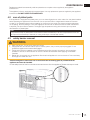
SAFETY BARRIER
A barrier designed to reduce the risk of burns from the hot viewing glass is provided with the
appliance and must be installed.
Lift the safety barrier off the four shoulder screws and remove from the appliance. Reverse this step to install.
!
WARNING
• Glass may be hot. Do not touch glass until cooled.
• If equipped with door latches that are part of a safety system, they must be properly engaged. Do not
operate the appliance with latches disengaged.
• Facing and/or fi nishing materials must not interfere with air fl ow through air openings, louvre openings,
operation of louvres, or doors/access for service. Observe all clearances when applying combustible
materials.
• Before door is removed, turn the appliance off and wait until appliance is cool to the touch. Doors are heavy
and fragile so handle with care.
4.3 safety barrier removal

W415-2760 / D / 04.20.21
EN
16
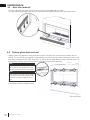
maintenance
To remove, slide the back edge of the door trim up and out of the glass and door frame.
To install, slide the back edge of the door trim down between the glass and door frame. Insert downwards.
4.4 door trim removal
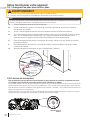
These spring latches make up the spring
relief system for the appliance. Ensure
the door opens freely and closes sealed.
note:
When mounting the door, ensure there is
equal space on both left and right sides.
This allows for easy installation of the
front.
note:
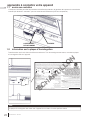
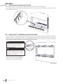
CBL46 illustrated
Leave a hand on the glass door during entire door removal. The glass door is secured to the fi rebox with four
(CBL36-1) or six (CBL46) spring latches. Pull the handles of the latches forward, then lift the latches out from the
door frame to release the door. Next, lift the door up until the bottom edge clears the bottom shoulder screws of
the appliance. Carefully grip the top and bottom of the door, lifting it off the appliance.
Reverse these steps to reinstall the door.
Ensure safety screen is installed correctly.
4.5 fi rebox glass door removal

EN
W415-2760 / D / 04.20.21
17
replacements
5.0 replacement parts
!
WARNING
• Failure to position the parts in accordance with this manual or failure to use only parts specifi cally approved
with this appliance may result in property damage or personal injury.
Contact your dealer for questions concerning prices and policies on replacement parts. Normally, all parts can
be ordered through your Authorized dealer / distributor.
For warranty replacement parts, a photocopy of the original invoice will be required to honour the
claim.
When ordering replacement parts always give the following information:
• Model & Serial Number of appliance
• Installation date of appliance
• Part number
• Description of part
• Finish
For service parts, see your Installation manual.

W415-2760 / D / 04.20.21
EN
18
accessories
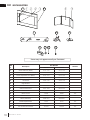
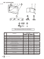
6.0 accessories
REF.
#
Description
Part Number
Stocked
CBL36-1 CBL46
1
Classic Side Trim (Black)
W715-1135 W715-1135
1
Premium Side Trim (Stainless Steel)
W715-1133 W715-1133
2
Classic Top/Bottom Trim (Black)
W715-1141 W715-1134
2
Premium Top/Bottom Trim (Stainless Steel)
W715-1140 W715-1132
3
Left Bracket
W080-1798 W080-1798
4
Right Bracket
W080-1797 W080-1797
5
Rear Porcelain Panel
W475-1060 W475-1374
6
Side Porcelain Panel
W475-1059 W475-1375
7
Shore Fire Kit
SFKS SFKM
Yes
8
Beach Fire Kit
BFKXS BFKM
Yes
9
Mineral Rock Kit
MRKXS MRKM
Yes
10
Blower (GZ600KT)
W062-0051 W062-0051
11
Variable Speed Switch
KB-35 KB-35
Yes
12
Thermodisc
W690-0002 W690-0002
Yes
13
Anti-Condensation Switch
ACS-SIT ACS-SIT
Yes
Items may not appear exactly as illustrated.
5453
52
551211
10
13
448
529
447
442 445441442441
446
443
444

EN
W415-2760 / D / 04.20.21
19
troubleshooting
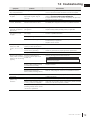
7.0 troubleshooting
symptom problem test solution
Flame is a blue,
Blockage in vent. - Remove blockage. In really cold conditions, ice buildup may
occur on the terminal and should be removed as required.
White / grey film forms
on glass.
Sulphur from fuel is being
depos
-
ited on glass, logs, or
-
surfaces.
- Clean the glass with a recommended gas fireplace glass
cleaner.
DO
NOT CLEAN GLASS WHEN HOT.
-
If sulphur deposits are not cleaned off regularly, the glass may
become permanently marked.
Exhaust fumes smelled
in room, headaches.
Appliance may be leaking
exhaust fumes into the room.
- Check firebox glass door was properly reinstalled after cleaning
If not rectified, turn off appliance. Contact a qualified technician.
Pilot will not light. Makes
noise with no spark at
pilot burner.
No siginal from remote with no
pilot ignition.
- Reprogram receiver code.
- Replace battery holder (including switch), if applicable.
Pilot sparks but will
not light.
Gas supply. - Contact a qualified technician.
Out of propane gas. - Fill the tank.
Remote control (if equipped). - Follow reprogramming instructions for specific remote
installed with your appliance.
- Replace remote control.
Battery holder (including
switch) is in “off”
position; burner comes
on.
Battery holder (including wall
switch) mounted upside down.
- Reverse.
Battery holder (including switch)
and/or wire is grounding.
- Replace.
- Check for ground (short); repair ground or replace wire.
Faulty wire - Replace.
Remote control and/or
battery holder (including
switch) is not functioning
properly.
Remote control lights but
no spark or flame. (Remote is
locked out).
- Reset by turning power source off then on.
Battery holder (including switch)
or remote has low battery.
- Replace batteries.
Error with synchronizing. - Reset battery holder (including switch) and remote control.
Remote too far away from
battery holder (including switch).
-
Refer to “wiring diagram” section in the Installation manual.
If back up batteries are installed, they must also be
removed to re-program
note:
Flames are very
aggressive.
Door is open. - Ensure door is secured properly. If not rectified, contact a
qualified technician.
Appliance won’t
perform any
functions.
No power to the system.
- Check breaker to verify it’s in the “on” position.
Battery holder (including switch)
in wrong position (if equipped).
- Verify that the 3 position switch on the battery holder (including
switch) is in the remote position (middle).
Battery holder, battery holder
(including switch) and/or remote
control isn’t operational.
-
Check battery power and battery orientation.
lazy, transparent flame

W415-2760 / D / 04.20.21
EN
20
warranty
8.0 warranty
Continental® warrants its products against manufacturing defects to the original purchaser only. Registering your warranty
is not necessary. Simply provide your proof of purchase along with the model and serial number to make a warranty
claim. Continental® reserves the right to have its representative inspect any product or part thereof prior to honouring any
warranty claim. Provided that the purchase was made through an authorized Continental® dealer your appliance is subject
to the following conditions and limitations:
Warranty coverage begins on the date of original installation. This factory warranty is non-transferable and may not be
extended whatsoever by any of our representatives. The gas appliance must be installed by a licensed, authorized service
technician or contractor. Installation must be done in accordance with the installation instructions included with the product
and all local and national building and fi re codes. This limited warranty does not cover damages caused by misuse,
lack of maintenance, accident, alterations, abuse or neglect, and parts installed from other manufacturers will nullify this
warranty. This limited warranty further does not cover any scratches, dents, corrosion or discoloring caused by excessive
heat, abrasive and chemical cleaners nor chipping on porcelain enamel parts, mechanical breakage of Phazer™ logs and
embers. In the fi rst year only, this warranty extends to the repair or replacement of warranted parts which are defective in
material or workmanship provided that the product has been operated in accordance with the operation instructions and
under normal conditions. After the fi rst year, with respect to this Limited Warranty, Continental® may, at its discretion, fully
discharge all obligations with respect to this warranty by refunding to the original warranted purchaser the wholesale price
of any warranted but defective part(s).
Continental® will not be responsible for installation, labour, or any other expenses related to the reinstallation of a warranted
part and such expenses are not covered by this warranty. Notwithstanding any provisions contained in the Limited
Warranty, Continental®’s responsibility under this warranty is defi ned as above and it shall not in any event extend to
any incidental, consequential or indirect damages. This warranty defi nes the obligations and liability of Continental® with
respect to the Continental® gas appliance and any other warranties expressed or implied with respect to this product,
its components or accessories are excluded. Continental® neither assumes, nor authorizes any third party to assume,
on its behalf, any other liabilities with respect to the sale of this product. Continental® will not be responsible for: over-
fi ring, downdrafts, spillage caused by environmental conditions such as rooftops, buildings, nearby trees, hills, mountains,
inadequate vents or ventilation, excessive venting confi gurations, insuffi cient makeup air, or negative air pressures which
may or may not be caused by mechanical systems such as exhaust fans, furnaces, clothes dryers, etc. Any damages to
the appliance, combustion chamber, heat exchanger, plated trim or other components due to water, weather damage,
long periods of dampness, condensation, damaging chemicals or cleaners will not be the responsibility of Continental®. All
parts replaced under the Limited Warranty Policy are subject to a single claim.
All parts replaced under the warranty will be covered for a period of 90 days from the date of their installation. The
manufacturer may require that defective parts or products be returned or that digital pictures be provided to support
the claim. Returned products are to be shipped prepaid to the manufacturer for investigation. If a product is found to be
defective, the manufacturer will repair or replace such defect. Before shipping your appliance or defective components,
your dealer must obtain an authorization number. Any merchandise shipped without authorization will be refused and
returned to sender. Shipping costs are not covered under this warranty. Additional service fees may apply if you are seeking
warranty service from a dealer. Labour, travel diagnostic tests, shipping and other related charges are not covered by this
warranty.
Continental® products are manufactured under the strict standard of the world recognized ISO 9001 : 2015 Quality
Management System.
Continental® products are designed with superior components and materials assembled by trained craftsmen who take great
pride in their work. The burner and valve assembly are leak and test-fi red at a quality test station. The complete appliance is
again thoroughly inspected by a qualifi ed technician before packaging to ensure that you, the customer, receives the quality
product that you expect from Continental®.
The following materials and workmanship in your new Continental® gas appliance are warranted against defects for a
period of 5 years, this covers: combustion chamber, heat exchanger, stainless / steel burner, Phazer™ logs and embers,
rocks, ceramic glass (thermal breakage only), gold plated parts against tarnishing, porcelainized enameled components and
aluminum extrusion trims.*
Electrical (110V and millivolt) components and wearable parts are covered and Continental® will provide replacement parts
free of charge during the fi rst year of the limited warranty. This covers: blowers, gas valves, thermal switches, switches,
wiring, remote controls, ignitors, gaskets and pilot assemblies.*
Any labour related to warranty repair is not covered.
* Construction of models vary. Warranty applies only to components included with your specifi c appliance.
Continental® Gas Appliance Limited Warranty
Conditions and Limitations
All specifi cations and designed are subject to change without prior notice due to on-going product improvements. Continental® is a
registered trademark of Wolf Steel Ltd.
La page est en cours de chargement...
La page est en cours de chargement...
La page est en cours de chargement...
La page est en cours de chargement...
La page est en cours de chargement...
La page est en cours de chargement...
La page est en cours de chargement...
La page est en cours de chargement...
La page est en cours de chargement...
La page est en cours de chargement...
La page est en cours de chargement...
La page est en cours de chargement...
La page est en cours de chargement...
La page est en cours de chargement...
La page est en cours de chargement...
La page est en cours de chargement...
La page est en cours de chargement...
La page est en cours de chargement...
La page est en cours de chargement...
La page est en cours de chargement...
La page est en cours de chargement...
La page est en cours de chargement...
La page est en cours de chargement...
La page est en cours de chargement...
-
 1
1
-
 2
2
-
 3
3
-
 4
4
-
 5
5
-
 6
6
-
 7
7
-
 8
8
-
 9
9
-
 10
10
-
 11
11
-
 12
12
-
 13
13
-
 14
14
-
 15
15
-
 16
16
-
 17
17
-
 18
18
-
 19
19
-
 20
20
-
 21
21
-
 22
22
-
 23
23
-
 24
24
-
 25
25
-
 26
26
-
 27
27
-
 28
28
-
 29
29
-
 30
30
-
 31
31
-
 32
32
-
 33
33
-
 34
34
-
 35
35
-
 36
36
-
 37
37
-
 38
38
-
 39
39
-
 40
40
-
 41
41
-
 42
42
-
 43
43
-
 44
44


Continental Fireplaces CBL36NTE-1 Manuel utilisateur
- Catégorie
- Cheminées
- Taper
- Manuel utilisateur
- Ce manuel convient également à
dans d''autres langues
Documents connexes
-
Continental Fireplaces CBL46NTE Le manuel du propriétaire
-
-
-
-
-
-
-
-
Autres documents
-
NAPOLEON BL46NTE Le manuel du propriétaire
-
-
-
-
-
 Nibart 1060-56 User's Installation, Operation And Maintenance Manual
-
-
-
-
