NAPOLEON L38N Le manuel du propriétaire
- Catégorie
- Cheminées
- Taper
- Le manuel du propriétaire

FRENCH
PG. 41
W415-2036 / A / 10.18.19
- Do not store or use gasoline or other fl ammable vapors and liquids in the vicinity of this or any other appliance.
- WHAT TO DO IF YOU SMELL GAS:
• Do not try to light any appliance.
• Do not touch any electrical switch; do not use any phone in your building.
• Immediately call your gas supplier from a neighbour’s phone. Follow the gas supplier’s instructions.
• If you cannot reach your gas supplier, call the fi re department.
- Installation and service must be performed by a qualifi ed installer, service agency, or the supplier.
WARNING
!
ENGLISH
For indoor use only
FIRE OR EXPLOSION HAZARD
Failure to follow safety warnings exactly could result in serious injury, death, or property damage.
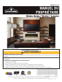
OWNER’S MANUAL
Acies / Vector / Luxuria Series
SAFETY INFORMATION
Wolf Steel Ltd., 24 Napoleon Rd., Barrie, ON, L4M 0G8 Canada / 103 Miller Drive, Crittenden, Kentucky, USA, 41030
Phone 1 (866) 820-8686 • www.napoleonfi replaces.com • [email protected]
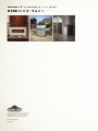
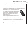
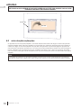
Luxuria model illustrated.

W415-2036 / A / 10.18.19
EN
2
safety information
• This appliance is hot when operated and can cause
severe burns if contacted.
• Any changes to this appliance or its control can be
dangerous and are prohibited.
• Do not operate appliance before reading and
understanding operating instructions. Failure
to operate appliance according to operating
instructions could cause fi re or injury.
• Risk of fi re or asphyxiation do not operate appliance
with fi xed glass removed.
• Do not connect 110 volts to the control valve.
• Risk of burns. The appliance should be turned off
and cooled before servicing.
• Do not install damaged, incomplete or substitute
components.
• Risk of cuts and abrasions. Wear protective gloves
and safety glasses during installation. Sheet metal
edges may be sharp.
• Children and adults should be alerted to the
hazards of high surface temperature and should
stay away to avoid burns or clothing ignition.
• Young children should be carefully supervised
when they are in the same room as the appliance.
Toddlers, young children, and others may be
susceptible to accidental contact burns. A
physical barrier is recommended if there are at
risk individuals in the house. To restrict access to
an appliance or stove, install an adjustable safety
gate to keep toddlers, young children and other at
risk individuals out of the room and away from hot
surfaces.
• Clothing or other fl ammable material should not be
placed on or near the appliance.
• Due to high temperatures, the appliance should be
located out of traffi c and away from furniture and
draperies.
• Ensure you have incorporated adequate safety
measure to protect infants/toddlers from touching
hot surfaces.
• Even after the appliance is out, the glass and/or
screen will remain hot for an extended period of
time.
• Check with your local hearth specialty dealer
for safety screens and hearth guards to protect
children from hot surfaces. These screens and
guards must be fastened to the fl oor.
• Any safety screen, guard or barrier removed for
servicing the appliance, must be replaced prior to
operating the appliance.
• The appliance is a vented gas-fi red appliance. Do
not burn wood or other materials in the appliance.
• The appliance area must be kept clear and free
from combustible materials, gasoline and other
fl ammable vapors and liquids.
!
WARNING
• Under no circumstances should this appliance be
modifi ed.
• This appliance must not be connected to a chimney
fl ue pipe serving a separate solid fuel burning
appliance.
• Do not use this appliance if any part has been
under water. Immediately call a qualifi ed service
technician to inspect the appliance and to replace
any part of the control system and any gas control
which has been under water.
• Do not operate the appliance with the glass door
removed, cracked or broken. Replacement of the
glass should be done by a licensed or qualifi ed
service person.
• Do not strike or slam shut the appliance glass door.
• When equipped with pressure relief doors, they
must be kept closed while the appliance is
operating to prevent exhaust fumes containing
carbon monoxide, from entering into the home.
Temperatures of the exhaust escaping through
these openings can also cause the surrounding
combustible materials to overheat and catch fi re.
• Only doors / optional fronts certifi ed with the unit
are to be installed on the appliance.
• Keep the packaging material out of reach of
children and dispose of the material in a safe
manner. As with all plastic bags, these are not toys
and should be kept away from children and infants.
• As with any combustion appliance, we recommend
having your appliance regularly inspected and
serviced as well as having a carbon monoxide
detector installed in the same area to defend you
and your family against carbon monoxide.
• Ensure clearances to combustibles are maintained
when building a mantel or shelves above the
appliance. Elevated temperatures on the wall or
in the air above the appliance can cause melting,
discolouration or damage to decorations, a T.V. or
other electronic components.
• A barrier designed to reduce the risk of burns from
the hot viewing glass is provided with this appliance
and shall be installed.
• If the barrier becomes damaged, the barrier shall
be replaced with the manufacturer’s barrier for this
appliance.
• Installation and repair should be done by a qualifi ed
service person. The appliance should be inspected
before use and at least annually by a professional
service person. More frequent cleaning may be
required due to excessive lint from carpeting,
bedding material, etc. It is imperative that control
compartments, burners and circulating air
passageways of the appliance be kept clean.
!
WARNING:
This product can expose you to chemicals including lead and lead compounds,
which are known to the State of California to cause cancer, and chemicals including carbon
monoxide, which are known to the State of California to cause birth defects or other reproduc-
tive harm. For more information, go to www.P65Warnings.ca.gov.

EN
W415-2036 / A / 10.18.19
3
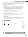
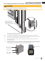
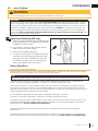
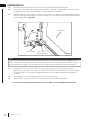
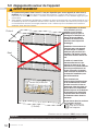
clear space
Fireplaces
generate radiant
heat. Do not put
objects in front
of the appliance
(minimum
distance of 4 feet
[1.21m]).
If fi tted with Dynamic Heat Control™
(DHC), DO NOT COVER OR PLACE
ITEMS AT AIR OUTLET OPENINGS!*
!
WARNING
The area above a fi replace gets hot,
(unless the appliance is fi tted with
Napoleon’s Dynamic Heat Control™
system). Combustible objects or mate-
rials must never be placed in this area.
For minimum distance, refer to installa-
tion manual or your authorized dealer.
!
WARNING
*The DHC air outlet is shown at the front of
the fi replace enclosure (see
illustration), however it may be located at
ceiling height, it may be in the room
behind or in both rooms.
Dynamic Heat Control™ is optional on the Vector series (LV models) and included on the Luxuria series (LVX
models). Dynamic Heat Control™ is not available for the Acies series (L models). [PATENT PENDING]
note:
FIRE HAZARD!
The air that comes out of the DHC air
outlet is very hot. NEVER PLACE OR
ALLOW ITEMS TO FALL INSIDE THE
DHC OUTLET AIR OPENING.
HOT GLASS WILL CAUSE BURNS.
DO NOT TOUCH GLASS UNTIL
COOLED.
NEVER ALLOW CHILDREN TO
TOUCH GLASS.
!
DANGER
A barrier designed to reduce the risk of burns from
the hot viewing glass is provided with this appliance
and shall be installed for the protection of children
and other at-risk individuals.

W415-2036 / A / 10.18.19
EN
4
welcome
Luxuria
Dealer Information
Name of Dealer:
Dealer Location:
Dealer Phone:
Dealer E-mail:
Customer:
Customer Address:
Date of Installation:
Location of the appliance:
Installer:
Napoleon is proudly committed to your total home comfort. We are proud to say that our products continunously
surpass industry standards and our inspiration is you! More than anything, we want you to feel confi dent in
choosing Napoleon for your home. Our products are designed to provide that confi dence and ensure that every
Napoleon product is beyond compare.
Napoleon products are designed with superior components and materials assembled by trained craftsmen who
take great pride in their work.
A barrier designed to reduce the risk of burns from the hot viewing glass is provided with the appliance for your
safety. This barrier must be installed.
Your Napoleon fi replace has been thoroughly inspected by a qualifi ed technician before packaging to ensure that
you, the customer, receives the quality product that you expect from Napoleon.
Dealer : Fill in your dealer information (or business card) and the appliance installation information below.
congratulations
Model:
L38N
L50N
LV38N-1
LV50N-2
LV62N
LV74N
LVX38N-1
LVX50N-1
LVX62N-1
LVX74N-1
L38N2
L50N2
LV38N2-1
LV50N2-2
LV62N2
LV74N2
LVX38N2-1
LVX50N2-1
LVX62N2-1
LVX74N2-1
L38P
L50P
LV38P-1
LV50P-2
LV62P
LV74P
LVX38P-1
LVX50P-1
LVX62P-1
LVX74P-1
L38P2
L50P2
LV38P2-1
LV50P2-2
LV62P2
LV74P2
LVX38P2-1
LVX50P2-1
LVX62P2-1
LVX74P2-1
Serial Number:
Dynamic Heat Control installed (Optional for LV / included for LVX)*
*Dynamic Heat Control™ not available for L models.
Dealer: Business card location
Acies
Propane:
Natural Gas:
Vector
Vector or
Luxuria

EN
W415-2036 / A / 10.18.19
5
table of contents
1.0 getting to know your appliance 6
1.1 control access 7
1.2 rating plate / lighting instructions location 8
2.0 operating your appliance 9
2.1 using your appliance (L models only) 9
2.2 using your appliance (LV / LVX models only) 9
2.3 on/off components 9
2.4 operating and lighting instructions 10
2.5 pilot-on-demand 11
2.5.1 changing the batteries in the battery holder (L models only) 12
2.5.2 turndown (L models only) 12
2.5.3 changing the batteries in the remote / battery holder (including switch) 13
3.0 remote control layout 14
4.0 remote control operation (optional for L models) 15
4.1 remote control operation 15
4.2 temperature display 15
4.3 fl ame height time 15
4.4 child proof function 15
4.5 LEDs 15
4.6 night light dimmer control 15
4.7 continuous pilot / intermittent pilot (CPI / IPI) selection 16
4.8 low battery / manual bypass 16
4.9 in the event of a power failure 16
4.10 eFIRE Controller application (optional for L models) 16
4.11 LED on/off light control (LV / LVX only) 17
5.0 clearances around fireplace 18
5.1 Dynamic Heat Control™ (LV optional / LVX included) 19
6.0 maintenance 20
6.1 care of glass 21
6.2 care of plated parts 22
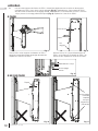
6.3 glass guard assembly (GGA-1) removal / installation (LVX models only) 23
6.4 safety barrier removal (L / LV models only) 32
6.5 door trim removal 32
6.6 fi rebox glass door removal 33
7.0 replacement parts 34
8.0 accessories 35
9.0 troubleshooting 37
10.0 faq 38
11.0 warranty 39
The camera icon indicates video tutorials are available as additional reference, visit
http://mynapoleon.napoleonproducts.com/download/index/44/1

W415-2036 / A / 10.18.19
EN
6
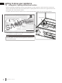
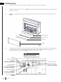
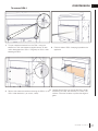
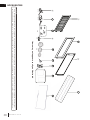
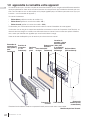
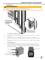
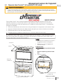
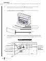
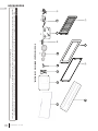
appliance components
1.0 getting to know your appliance
BurnerPilot
Glass guard
assembly
(LVX only)
Safety barrier
(L / LV only)
Door trim
Firebox
glass door
Glass guard
mounting
brackets
(LVX only)
Some features and components illustrated may vary depending on your model.
Heat rail
(LVX only)
Control cover
Valve / rating
plate / lighting
instructions /
battery holder (L
only) location
Single-sided model illustrated.
Battery holder
(including switch)
(LV/LVX only)
This owner’s manual is written for a complete series of linear fi replaces that have a range of different features and
specifi cations. Before reading this manual, be sure you know which model of fi replace that you have. This informa-
tion will have been fi lled out by the installer on the proceeding page and on the rating plate that is permanently
attached to the fi replace (see “appliance overview” section).
This manual is for the:
• Acies Series (model number prefi x “L”)
• Vector Series (model number prefi x “LV”)
• Luxuria Series (model number prefi x “LVX”)
If required, more detailed technical information is included in the fi replace installation manual.
The information throughout this manual is believed to be correct at the time of printing. Wolf Steel Ltd. reserves
the right to change or modify any information within this manual at any time without notice. Changes, other than
editorial are denoted by a vertical line in the margin.
Visit the Napoleon website for the most current version of your appliance’s manual.

EN
W415-2036 / A / 10.18.19
7
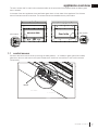
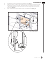
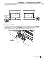
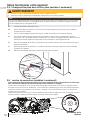
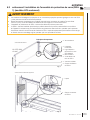
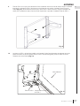
appliance overview
The term “access side” is used in this manual and refers to the open side of the fi replace where the fi rebox glass
door is located.
In the case of see-thru appliances, there are fi rebox glass doors on both sides of the appliance. One of these
doors is fi xed and cannot be removed. The access side can be identifi ed with the pilot location.
access side
fi xed side
pilot location
pilot location
Access to the control can be done by removing the safety barrier (L / LV models) or glass guard (LVX models),
glass door, door trim and control cover (see “maintenance” section for instructions on how to remove these
components).
ELECTRICAL
BOX
CONTROL
MODULE
VALVE
PRE-FINISHING
ACCESS PANEL
1.1 control access

W415-2036 / A / 10.18.19
EN
8
getting to know your appliance
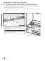
1.2 rating plate / lighting instructions location
CERTIFIED UNDER / HOMOLOGUE SELON LES NORMES: CSA 2.33
b
- 2008, ANSI Z21.88
b
- 2008 VENTED GAS FIREPLACE HEATER / APPAREIL DE CHAUFFAGE ALIMENTÉ
AU GAZ ET VENTILÉ
VENTED GAS FIREPLACE HEATER. APPROVED FOR BEDROOM, BATHROOM AND BED-SITTING ROOM INSTALLATION. SUITABLE FOR MOBILE HOME INSTALLATION IF INSTALLED IN ACCORDANCE WITH THE
CURRENT STANDARD CAN/CSA Z240MH SERIES GAS EQUIPPED MOBILE HOMES, IN CANADA OR IN THE UNITED STATES THE MANUFACTURED HOME CONST
RUCTION AND SAFETY STANDARD, TITLE 24 CFR,
PART 3280. WHEN THIS US STANDARD IS NOT APPLICABLE USE THE STANDARD FOR FIRE SAFETY CRITERIA FOR MANUFACTURED HOME INSTALLATION
S, SITES AND COMMUNITIES, ANSI / NFPA 501A.
FOYER DE CHAUFFAGE AU GAZ AVEC ÉVACUATION. HOMOLOGUÉ POUR INSTALLATION DANS UNE CHAMBRE À COUCHER, UNE SALLE DE BAIN ET UN STUDIO. APPROPRIÉ POUR INSTALLATION DANS UNE
MAISON MOBILE SI SON INSTALLATION CONFORME AUX EXIGENCES DE LA NORME CAN/CSA Z240MH SÉRIE DE MAISONS MOBILES ÉQUIPÉES AU GAZ, E
N VIGUEUR AU CANADA OU AUX ÉTATS-UNIS DE LA
NORME DE SECURITÉ ET DE CONSTRUCTION DE MAISONS MANUFACTURÉES, TITRE 24 CFR, SECTION 3280. DANS LE CAS OU CETTE NORME D'ÉTATS-U
NIS NE PEUT ÊTRE APPLIQUÉE, SE RÉFÉRER A LA NORME
RELATIVE AU CRITÈRE DE MESURES DE SÉCURITÉ CONTRE L'INCENDIE POUR LES INSTALLATIONS DANS LES MAISONS MANUFACTURÉS, LES SITES ET
LES COMMUNAUTÉS, ANSI/NFPA 501A.
NOT FOR USE WITH
SOLID FUEL. FOR USE
WITH GLASS DOORS
CERTIFIED WITH THIS
UNIT ONLY.
WARNING
:
DO NOT ADD ANY MATERIAL
TO THE APPLIANCE, WHICH WILL COME
IN CONTACT WITH THE FLAMES, OTHER
THAN THAT SUPPLIED BY THE
MANUFACTURER WITH THE APPLIANCE.
MINIMUM CLEARANCE TO
COMBUSTIBLE MATERIALS:
TOP 0”
FLOOR 0”
RECESSED DEPTH ONE SIDED 23"
RECESSED DEPTH SEE THRU 13.5”
FRAMING (NOT INCLUDING
FACE MATERIAL)
SIDES 0”
VENT 2"
BACK 0”
MANTLE 15" *
TOP, SIDES & BACK: PER STAND OFF SPACERS FOR FRAMING MATERIALS. FOR FINISHING MATERIALS
SEE OWNERS MANUAL
UN COMBUSTIBLE SOLIDE NE
DOIT PAS ÊTRÉ UTILISÉ AVEC
CET APPAREIL. UTILISER AVEC
LES PORTES VITRÉES
HOMOLOGUÉES SEULEMENT
AVEC CETTE UNITÉ.
AVERTISSEMENT:
N'AJOUTEZ PAS A
CET APPAREIL AUCUN MATÉRIAU DEVANT
ENTRER EN CONTACT AVEC LES FLAMMES
AUTRE QUE CELUI QUI EST FOURNI AVEC
CET APPAREIL PAR LE FABRICANT.
DÉGAGEMENTS MINIMAUX DES
MATÉRIAUX COMBUSTIBLES:
DESSUS 0”
PROFONDEUR D'ENCASTRÉ 25"
PLANCHER 0”
ÉVENT 2"
CÔTES 0”
MANTEAU 15" *
ARRIÉRE 0”
MADE IN CANADA / FABRIQUÉ AU CANADA
WOLF STEEL LTD. BARRIE, ONTARIO, CANADA
ALTITUDE / ÉLÉVATION
INPUT / ALIMENTATION
REDUCED INPUT / ALIMENTATION RÉDUITE
ORIFICE / INJECTEUR
MANIFOLD PRESSURE /
PRESSION AU COLLECTEUR
MINIMUM SUPPLY PRESSURE /
PRESSION D'ALIMENTATION MINIMALE
MAXIMUM SUPPLY PRESSURE /
PRESSION D'ALIMENTATION MAXIMALE
0-4500FT (0-1370M)
30,000 BTU/H
23,000 BTU/H
#38
3.5" WATER COLUMN/D'UNE COLONNE D'EAU
4.5" WATER COLUMN/D'UNE COLONNE D'EAU
7.0" WATER COLUMN/D'UNE COLONNE D'EAU
0-4500FT (0-1370M)
30,000 BTU/H
23,000 BTU/H
#53
10" WATER COLUMN/D'UNE COLONNE D'EAU
11" WATER COLUMN/D'UNE COLONNE D'EAU
13" WATER COLUMN/ D'UNE COLONNE D'EAU
THE APPLIANCE MUST BE VENTED USING THE APPROPRIATE
NAPOLEON VENT KITS. SEE OWNERS INSTALLATION MANUAL
FOR VENTING SPECIFICS. PROPER REINSTALLATION AND
RESEALING IS NECESSARY AFTER SERVICING THE VENT-AIR
INTAKE SYSTEM.
L'APPAREIL DOIT ÉVACUER SES GAZ EN UTILISANT L'ENSEMBLE
D'ÉVACUATION PROPRE A NAPOLEON. RÉFÉRER AU MANUEL
D'INSTALLATION DE PROPRIÉTAIRE POUR L'ÉVACUATION
PRÉCISE. IL EST IMPORTANT DE BIEN RÉINSTALLER ET
RESCELLER L'ÉVENT APRÈS AVOIR ASSURÉ LE MAINTIEN DU
SYSTÉME DE PRISE D'AIR.
CLASSIFICATION: 115V 0.82AMP, 60HZ
W385-2007
MODEL NATURAL GAS /
GAZ NATURAL
LHD50NT
MODEL PROPANE
LHD50PT
SERIAL NUMBER/NO. DE SÉRIE:
LV50
ELECTRICAL RATING: 115V 0.82AMP, 60HZ
REFERENCE #
W/N 16131
* MAXIMUM HORIZONTAL EXTENSION / L'EXTENSION
HORIZONTALE MAXIMALE: 2". SEE INSTRUCTION MANUAL FOR GREATER EXTENSIONS.
SEE OWNER'S INSTRUCTION MANUAL FOR MINIMUM AND MAXIMUM VENT LENGTHS.
DESSUS, COTÉS & ARRIÈRE: SELON LES ESPACEURS DE DÉGAGEMENT POUR LES MATÉRIAUX D'OSSATURE
SELON LE MANUEL DE PROPRIÉTAIRE POUR LES MATÉRIAUX DE FINITION.
* L'EXTENSION HORIZONTALE MAXIMALE: 2". RÉFÉRER AU MANUEL D'INSTRUCTION POUR DES EXTENSIONS
PLUS GRANDES. RÉFÉRER AU MANUEL D'INSTALLATION DE PROPRIÉTAIRE.
Both the rating plate and lighting instructions are attached to a chain located on the left side of the control area
near the valve (access side). Remove the safety barrier or glass guard and the control cover to gain access to the
control area, see “control access” section.
To replace, slide the instructions back into the control area and slide the glass front into its locked position.
This illustration is for reference only. Refer to the rating plate on
the appliance for accurate information.
The rating plate must remain with the appliance at all times. It
must not be removed.
note:
Pilot location
Valve location
Certified to Canadian and American National Standards: CSA 2.22-XXXX / ANSI Z21.50-XXXX for Vented Decorative Gas Appliances
Certifié selon les normes Nationales Canadiennes et Américaines: CSA 2.22-XXXX / ANSI Z21.50-XXXX pour les Appareils à gaz décoratif à évacuation
Direct vent, vented gas fireplaces. Approved for bedroom, bathroom and bed-sitting room installation. Suitable for mobile home installation, if installed in accordance with the current
standard CAN / CSA Z240MH Series gas equipped mobile homes in Canada, or, in the United States, the Manufactured Home Construction and Safety Standard, Title 24 CFR, Part
3280. When this US Standard is not applicable, use the Standard for Fire Safety Criteria for Manufactured Home Installations, Sites and Communities, ANSI / NFPA 501A. This appliance
must be installed in accordance with local codes, if any; if none, follow the current ANSI Z223.1 or CSA B149. For use with barrier WXXX-XXXX. Follow installation instructions.
Foyer à gaz ventilé. Homologué pour installation dans une chambre à coucher, une salle de bain et un studio. Approprié pour installation dans une maison mobile si son installation
conforme aux exigences de la norme CAN / CSA Z240MH Séries de maisons mobile équipées au gaz en vigueur au Canada, ou, aux États-Unis selon la norme 24 CFR, Part 3280,
Manufactured Home Construction and Safety Standard. Dans le cas ou cette norme d’États-Unis n’est pas pertinentes, utiliser la norme NFPA 501A, Fire Safety Criteria for Manufactured
Home Installations, Sites and Communities. Installer l’appareil selon les codes ou règlements locaux ou, en l’absence de tels règlements, selon les codes d’installation ANSI Z223.1 ou
CSA B149 en vigueur. Utiliser uniquement avec l’écran WXXX-XXXX. Suivre les instructions d’installation.
9700539 (WSL) 4001658 (NAC) 4001657 (NGZ) 4001659 (WUSA)
WOLF STEEL LTD. 24 Napoleon Road, Barrie, ON, L4M 0G8 Canada
XXXX XXXX XXXX XXXX
MODEL / MODÈLE
Altitude
Input
Reduced Input
P4
Élévation
Alimentation
Alimentation Réduite
P4
Manifold Pressure: 3.5” w.c. (NG)
Minimum Supply Pressure: 4.5” w.c. (NG)
Maximum Supply Pressure: 7”* w.c. (NG)
Pression au Collecteur: 3,5” d’une colonne d’eau (GN)
Pression d’Alimentation Min.: 4,5” d’une colonne d’eau (GN)
Pression d’Alimentation Max.: 7” ** d’une colonne d’eau (GN)
** Maximum inlet pressure not to exceed 13”.
Manifold Pressure: 10” w.c. (P)
Minimum Supply Pressure: 11” w.c. (P)
Maximum Supply Pressure: 13”* w.c. (P)
Pression au Collecteur: 10” d’une colonne d’eau (P)
Pression d’Alimentation Min.: 11” d’une colonne d’eau (P)
Pression d’Alimentation Max.: 13” * d’une colonne d’eau (P)
** Pression d’alimentation maximale ne devait pas dépasser 13”.
0-XXXXft (0-XXXXm)
Minimum clearance to combustible materials:
Top, sides & back: per standoff spacers for framing and finishing
materials. For non-combustible framing and finishing materials,
see installation manual.
Top X”
Floor X”
Sides X”
Back X”
Vent top X”
Vent sides & bottom X”
Recessed depth X”
*** Mantel X” from appliance opening
Dégagements minimaux des matériaux combustibles:
Dessus, côtés et arrière: selon les espaceurs de dégagements
pour les matériaux d’ossature selon le manuel du propriétaire
pour les matériaux de finition.
Dessus X”
Plancher X“
Côtés X”
Arrière X“
Dessus du conduit d’évent X”
Côtés et dessous du conduit d’évent X”
Profondeur d’encastré une face X”
*** Tablette X” de l’ouverture de l’appareil
WARNING: Do not add any material to the appliance which will come in contact with the
flames, other than that supplied by the manufacturer with the appliance.
AVERTISSEMENT: N’ajoutez pas à cet appareil aucun matériau devant entretien
contact avec les flammes autre que celui qui est fourni avec cet appareil par le fabricant.
*** Maximum horizontal extension:
X”. See installation manual for
greater extensions, minimum vent
lengths and maximum vent lengths.
*** L’extension horizontale maximale: X”.
Référez au manuel d’installation pour des
extensions plus grandes, les longueurs
d’évacuation minimaux et maximum.
The appliance must be vented using the appropriate Napoleon vent kits. See installation
manual for venting specifications. Proper reinstallation and resealing is necessary after servicing
the vent-air intake system.
L’appareil doit être ventilé à l’aide de l’ensemble d’évacuation propre à Napoleon. Référez au
manuel d’installation pour les spécifications d’évacuation. Il est nécessaire de bien réinstaller et
resceller l’évacuation après avoir executer l’entretien du système de prise d’air.
Serial Number / N° de Série:
W385-XXXX
REFERENCE# 161746
XXXX
VENTED DECORATIVE GAS APPLIANCE: NOT A SOURCE OF
HEAT, NOT INTENDED FOR USE AS A HEATING
APPLIANCE, NOT FOR USE WITH SOLID FUEL.
APPAREIL À GAZ DÉCORATIF À ÉVACUATION: N’EST PAS
UNE SOURCE DE CHALEUR; N’EST PAS DESTINÉ À ÈTRE
UTILISÉ COMME UN APPAREIL DE CHAUFFAGE; NE
CONVIENT PAS AUX COMBUSTIBLES SOLIDES.
FOR USE WITH GLASS DOORS CERTIFIED WITH THIS APPLIANCE ONLY.
POUR UTILISATION UNIQUEMENT AVEC LES PORTES EN VERRE
CERTIFIÉES AVEC L’APPAREIL.
XX,XXX XX,XXX
XX,XXX XX,XXX
For natural gas when equipped with No. XX drill size orifice.
For propane when equipped with No. XX drill size orifice.
Convient au gaz naturel quand l’appareil est muni d’un injecteur de diamètre no. XX.
Convient au propane quand l’appareil est muni d’un injecteur de diamètre no. XX.
Electrical rating: 115V, 60HZ. Less than 12 amperes.
Spécifications électriques: 115V, 60HZ. Moins de 12 ampère.
XX.X% XX.X%
XXXX XXXX XXXX XXXX
SAMPLE
Manufactured
ion
ANSI Z223.1 ou
É
lévatio
névation
Ali
mentat
i
o
nntation
Alim
e
nt
a
ti
o
n R
édu
it
eAlimentation Réduite
P4P4
G)
une colonne d’eau (GN)eau (GN)
n Min.:
4,5” d’une colonne d’eau
(
GN
)onne d’eau (GN)
entation Max.: entation Ma
7” ** d’une colonne d’eau
(
GN
)onne d’eau (GN)
mum inlet pressure not to exceed 13”.m inlet pressure not to e
M
an
if
o
ld
P
ressure:
nifold Pressure:
1
0” w.c.
(
P
)c. (P)
Minimum Su
pp
l
y
Pressure:
Minimum Supply Pressure:
11” w.c.
(
P
)11” w.c. (P)
Maximum
S
u
pp
l
y
Pressure:
Maximum Supply Pressure:
1
3”* w.c.
(
P
)13”* w.c. (P)
Pression au
C
ollecteur:
Pression au Collec
1
0” d’une colonne d’eau
(
P
)10” d’une colonne d’eau (P)
Pr
ess
i
o
n
d
’Alim
e
nt
a
ti
o
n Min.:
n d’Alimentation M
1
1” d’une colonne d’eau
(
P
)11” d’une colonne d’eau (P)
Pr
ess
i
o
n
d
’Alim
e
nt
a
ti
o
n M
a
x.:
d’Alimentation Max.:
1
3” * d’une colonne d’eau
(
P
)3” * d’une colonne d’
*
* Pression d’alimentation maximale ne devait
p
as d
ép
asser 13”
.** Pression d’alimentation maximale ne devait pas dépasse
inimum clearance to combustible materials:
m clearance to combustible materials:
p, sides & back: per standoff spacers for framing and finishing
des & back: per standoff spacers for framing and finishing
terials. For non-combustible framing and finishing materials,
als. For non-combustible framing and finishing materials,
installation manual.
stallation m
X”
X”
X”
X”
s & bottom X”& bottom
depth X”depth X”
X” from appliance opening” from appliance opening
Dégagements minimaux des matériaux combustibles:ments minimaux des matériaux combusti
Dessus, côtés et arrière: selon les espaceurs de dégagemenDessus, côtés et arrière: selon les espaceurs de dégagem
pour les matériaux d’ossature selon le manuel du ppour les matériaux d’ossature selon le m
pour les mpour les
*** Maximum horizontal * Maximum horizontal
X”. See installat
greater
REFEREN
# 16
D DECORATIVE GAS APPLIANCE: NOT A SOURCERATIVE GAS APPLIANCE: NOT A SOURC
CNOASOU
HEAT, NOT INTENDED FOR USE AS A HEATINAT, NOT INTENDED FOR USE AS A
APPLIANCE, NOT FOR USE WITH SOLID FUEAPPLIANCE, NOT FOR USE WITH SOLID FUE
APPAREIL À GAZ DÉCORATIF À ÉVACUATION: N’EST PAAPPAREIL À GAZ DÉCORATIF À ÉVACUATION: N’EST PA
UNE SOURCE DE CHALEUR; N’EST PAS DESTINÉ À ÈTR
E SOURCE DE CHALEUR; N’EST PAS DESTINÉ À ÈTR
UTILISÉ COMME UN APPAREIL DE CHAUFFUTILISÉ COMME UN APPAREIL DE CHAUF
CONVIENT PAS AUX COMBUNT PAS AUX COM
FOR USE WITH GLASS DOORS CERTIFOR USE WITH GLASS DOORS CER
POUR UTILISATION UNNU
XXX
XX,XXXXX,X
XX.X%XX.X%
XXXXXXX
M

EN
W415-2036 / A / 10.18.19
9
operating your appliance
2.0 operating your appliance
To turn the appliance on:
When operating your appliance for the fi rst time, there is a required burn-in process that cures materials used
to manufacture the fi replace that may emit both vapors and an odor. These are normal when operating a new
appliance for the fi rst time. Ensure adequate air circulation is provided during burn-in process, if this was not
completed by the installer during installation.
To turn the appliance on:
2.1 using your appliance (L models only)
2.2 using your appliance (LV / LVX models only)
A For battery holder (including switch) operation: Turn the appliance on/off by turning the battery holder
(including switch) to the ‘on’ and/or ‘off’ position.
For remote control operation: Ensure the battery holder (including switch) is in the ‘remote’ position. Press and
release the on/off button on the remote control. An audible beep should be heard from the remote.
B After 3-5 seconds, the control will start a spark at the pilot, light the pilot and then the burner. The spark
period will last 60 seconds, or until the pilot has lit.
C When used for the fi rst time, if the burn-in process was not completed by the installer; run appliance
continuously for 4 hours.
D Turn the appliance off. Wait until appliance is completey cool before moving to the next step.
E Remove glass guard (LVX models) or safety barrier (LV models) and fi rebox glass door. Clean fi rebox glass
door (see “maintenance” section). Replace fi rebox glass door and glass guard/safety barrier.
A Turn the on/off switch on.
B After 3-5 seconds, the control will start a spark at the pilot, light the pilot and then the burner. The spark
period will last 60 seconds, or until the pilot has lit.
C When used for the fi rst time, if the burn-in process was not completed by the installer; run appliance
continuously for 4 hours (burn-in).
D Turn the appliance off. Wait until appliance is completely cool before moving to the next step.
E Remove the safety barrier and fi rebox glass door. Clean fi rebox glass door (see “maintenance” section).
Replace fi rebox glass door and safety barrier.
For more detailed information, see your installation manual or contact your authorized dealer.
| On/off switch | Battery holder | Battery holder (including switch) | Remote control |
(L only)
(Optional for L models)
(Optional for L models)
(Not supplied)
Batteries must be disposed of according to the local laws and regulations. Some batteries may be
recycled, and may be accepted for disposal at your local recycling center. Check with your
municipality for recycling instructions.
2.3 on/off components
For more detailed information, see your installation manual or contact your authorized dealer.
(Optional for LV / LVX
models)

W415-2036 / A / 10.18.19
EN
10
operating your appliance
!
WARNING
• Do not turn on if children or other at risk individuals are near the appliance.
• This appliance is equipped with an ignition device which automatically lights the pilot. Do not try to light the
pilot by hand.
• Before operating, smell all around the appliance area for gas and next to the fl oor because some gas is
heavier than air and will settle on the fl oor.
• Do not use this appliance if any part has been under water. Immediately call a qualifi ed service technician
to inspect the appliance and replace any part of the control system and any gas control which has been
underwater.
FOR YOUR SAFETY READ BEFORE LIGHTING
WHAT TO DO IF YOU SMELL GAS
LIGHTING INSTRUCTIONS
TO TURN OFF GAS
A. Stop! Read the above safety information on this label.
B. Remove batteries from the transmitter and set thermostat to lowest setting, if
equipped.
C. Turn off all electrical power to the appliance.
D. Open the glass door, if equipped.
E. Turn the manual shut-off valve clockwise to the “OFF” position. (Shut-off valve is
located on the fl ex connector).
F. Wait fi ve (5) minutes to clear out any gas. If you smell gas including near the
fl oor, STOP! Follow the instructions above in the “WHAT TO DO IF YOU
SMELL GAS” section. If you don’t smell gas; close the glass door and go to
the next step.
G. Turn the manual shut-off valve counter clockwise to the “ON” position.
H. Turn on all electrical power to the appliance and re-install the batteries into the
transmitter. Set thermostat to desired setting, if equipped.
I. Turn on the remote wall switch to the appliance.
J. If the appliance will not operate, follow instructions “TO TURN OFF GAS” and
call your service technician or gas supplier.
A. Set thermostat to lowest setting, if equipped.
B. Turn off the remote wall switch to the appliance.
C. Turn off all electric power to the appliance if service is to be performed.
D. Turn manual shutoff valve clockwise to the “OFF” positon. Do not force.
• Turn off all gas to the appliance.
• Open windows.
• Do not try to light any appliance.
• Do not touch any electric switch; do not use
any phone in your building
• Immediately call your gas supplier from a
neighbour’s phone. Follow the gas supplier’s
instructions.
• If you cannot reach your gas supplier, call
the fi re department.
• If you do not follow these instructions exactly, a fi re or explosion may result causing property damage, personal
injury, or loss of life.
• If applicable, always light the pilot whether for the fi rst time or if the gas supply has run out with the glass door
opened or removed.
add gas knob
add gas valve
Ensure that a continuous gas fl ow is at the burner before installing the door. When lit for the fi rst time, the
appliance will emit an odor for a few hours. This is a normal temporary condition caused by the “burn-in” of
paints and lubricants used in the manufacturing process and will not occur again. After extended periods of
non-operation, such as, following a vacation or warm weather season, the appliance may emit a slight odor for a
few hours. This is caused by dust particules in the heat exchanger burning off. In both cases, open a window to
suffi ciently ventilate the room.
This appliance is equipped with an ignition device which automatically lights the pilot. Do not try to light the
pilot by hand.
note:
2.4 operating and lighting instructions (electronic)

EN
W415-2036 / A / 10.18.19
11
operating your appliance
This appliance is equipped with an “On Demand” intermittent pilot ignition system (IPI) which also includes a
continuous pilot ignition (CPI) mode with an integrated seven day timer. This system minimizes your appliance’s
carbon footprint as well as reducing its annual fuel consumption and operating costs.
In IPI operation, the pilot will ignite prior to the main burner, when the appliance is turned on using a switch,
remote or from a call for heat with the thermostat (if equipped). Once the appliance is turned off (or the call for
heat is satisfi ed), the main burner and pilot fl ame will shut down.
The continuous (CPI) mode is intended to enhance the performance of the appliance during the startup phase in
colder climates and extreme weather by keeping the system warm when the main burner is not in use. However,
the timer feature provides the convenience that the appliance automatically switches off the pilot when the
appliance has not been used for seven days to save unnecessary fuel consumption.
When the CPI function is turned on, the pilot will remain on after the main burner
is turned off. A timer will then begin the countdown for approximately seven days
before shutting off the pilot if the appliance is not used. This countdown will reset
anytime the appliance main burner is used. Therefore, if the appliance is regularly
used day to day, the pilot will remain on. However, this system does not require
the user to remember to turn the pilot off as summer approaches and avoids
unnecessary fuel consumption while still readily turned back on when the cold
weather returns.
Your appliance may be equipped with an ACS or remote control device which
enables you to select IPI or CPI modes.
If your appliance is equipped with an ACS switch, it has the option to change
modes. If installed with the blue wire facing up, fl ipping the switch UP turns on the
continuous pilot with timer and fl ipping the switch DOWN turns on the intermittent
pilot ignition. If installed with the white wire facing up, the opposite is true.
If your appliance is equipped with a remote control device capable of selecting IPI / CPI modes, refer to remote
operating instructions.
In order to start your pilot, turning the main burner on with the switch, remote or thermostat and then turning it off
will reactivate the continuous pilot mode and reset the seven day timer.
For further information, refer to www.napoleon.com/pilotondemand.
ADD TITLE: PIL
O
T-
O
N-DEMAND
2.5 pilot-on-demand (electronic)

W415-2036 / A / 10.18.19
EN
12
operating your appliance
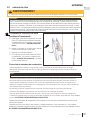
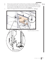
2.5.1 changing the batteries in the battery holder (L models only)
• Ensure the gas and electrical power to the appliance is turned off.
• Appliance may be hot, do not service until the appliance has cooled.
!
WARNING
A. Turn off the gas and disconnect the electrical power supply from the appliance.
B. Remove the safety barrier, control cover and door trim to easily access the control compartment (see
“maintenance” section for instructions on how to remove these components.
C. Locate the battery housing located near the control board (see illustration below).
D. Open the battery housing by sliding the back piece upwards and off of the battery housing. Remove the
four “AA” alkaline batteries and install four new “AA” alkaline batteries into the battery housing. Ensure the
positive and negative ends correspond with those identifi ed on the holder.
E. Place the battery housing back into the control compartment, ensure that the battery housing is placed in
a clean and easily accessible location.
F. Reinstall the safety barrier. The safety barrier must be installed at all times during the appliance operation.
G. Turn the gas and electrical power back on to begin operating the appliance.
In the event of a power failure, your appliance can be operated using the supplied battery back-up. If a power
failure occured, remove the batteries from the holder once the power has been restored. The system will drain
the batteries if they are left in the battery holder.
note:
Control module
Battery housing
Red wire
Black wire
2.5.2 turndown (L models only)
L
O
H
I
Flame adjustment
Manual adjustments to your fi replace must only be made when the appliance is off and complete cool.
Allow safety barrier to cool before making adjustment.
The Acies Series is equipped with a manual gas control knob (located on the valve) that adjusts the fl ame height to
suit your preference. To access the gas control knob, remove your safety barrier, control cover and door trim (see
“maintenance” section for instructions on how to remove these components.
Use only your hand to turn the gas control knob (never use tools). If the knob will
not turn by hand, do not try to repair it. Contact a qualifi ed technician.

EN
W415-2036 / A / 10.18.19
13
operating your appliance
2.5.3 changing the batteries in the remote / battery holder (including switch)
• Ensure the gas and electrical power to the appliance is turned off.
• Appliance may be hot, do not service until the appliance has cooled.
!
WARNING
(4) AA Batteries
ON REMOTE OFF
Y
BARRIER
(4) AA Batteries
ON REMOTE OFF
For battery holder (including switch):
A. Remove the two screws securing cover plate to battery holder (including switch). Do not discard.
B. Remove the 4 “AA” alkaline batteries in the battery holder (including switch) and replace with new ones.
Note the polarity of the batteries and insert as indicated on the cover (+/-).
C. Secure the cover plate to the battery holder (including switch) using the screws removed in step A.
For remote control:
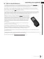
A. Press the securing clip on the back of the remote control to release the back cover. Remove the 3 “AAA”
alkaline batteries in the remote and replace with new batteries then press the ON button. The battery
holder will beep 4 times to indicate that the remote’s command is accepted.
(4) AA Batteries
Remote control
Reset / Program
Button (PRG)
Battery Holder
(including switch)
Slider Switch
(Illustrated with cover plate
removed)
Battery holder (including
switch) would have been
located close to the
appliance during installation

W415-2036 / A / 10.18.19
EN
14
transmitter layout
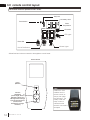
3.0 remote control layout
Low battery alarm
Key Lock
Room
Temperature
Light
Flame ON
Blower
Transmission
CPI mode
Remote Control
Power
(ON/OFF)
Function
Adjustment
(Flame Height, Hot Air
Distribution Speed, and
LED Light Colour Change)
Cycle Through Functions
(Flame, Hot Air
Distribution, and Light
Functions)
The remote control is optional for the L series.
note:
Install the 3 ‘AAA’
batteries into the
remote control, as
shown, then press
the ON button. The
battery holder will
beep 4 times to
indicate that the
remote’s command is
accepted.
note:
Accent Lights
LED Lights
Hot Air Distribution*
*Where fitted and where connected to the appliance control board.

EN
W415-2036 / A / 10.18.19
15
remote control operation
ADD TITLE: CHILD PROOF FUNCTION
This function will lock the keys to avoid unsupervised operation.
A. Press the mode and up keys at the same time.
B. To de-activate this function, press the mode and up keys at the same time.
76
°F
ADD TITLE: NIGHT LIGHT
The auxiliary function controls the AUX power outlet on the control module
which controls the Night Light™.
A. Use the mode key to guide you to the AUX icon.
B. Pressing the up arrow key will activate the Night Light™.
C. Pressing the down arrow key will turn the Night Light™ off. A single
“beep” will confi rm the reception of the command.
76
°F
OFF
76
°F
ON
A. Press the on / off key on the transmitter. The transmitter display will
show all active icons on the screen. A single “beep” from the receiver will
confi rm reception of the command.
Blue LCD Display
On / Off Key
Up / Down Arrow Key
Mode Key
Temperature Key
ADD TITLE: TEMPERATURE DISPLAY
A. With the system in the off position, press the temperature key
and the mode key at the same time to change from degrees ºF to
ºC.
B. Look at the LCD screen on the transmitter to verify that a ºC or ºF
is visible to the right of the room temperature display.
ADD TITLE: HAND HELD REMOTE OPERATION
The remote control has six (6) fl ame levels. With the system on and the fl ame level at the maximum, press the
down arrow key once and it will reduce the fl ame height by one step until the fl ame is turned off.
The up arrow key will increase the fl ame height each time it is pressed. If the up arrow key is pressed while
the system is on but the fl ame is off, the fl ame will come on at the high position. A single “beep” will confi rm
reception of the command.
ADD TITLE: FLAME HEIGHT
76
°F
OFF
76
°F
76
°F
76
°F
Hi
Flame Off Flame at level 1 Flame at level 5 Flame at “Hi” level 6
73 23
°F °C
4.0 remote control operation (optional for L models)
4.1 remote control operation
4.2 temperature display
4.3 fl ame height time
4.4 child proof function
LEDs.
LEDs.
LEDs off. A single
4.5 LEDs
ADD TITLE: Night Light Dimmer Control
76
°F
OFF
76
°F
The auxiliary function controls the Night Light™ with dimmable control.
A. Use the mode key to guide you to the Night Light™ icon.
B. The intensity of the output can be adjusted through 6 levels.
Use the up/down arrow keys to adjust the output level. A single beep
will confi rm reception of the command.
4.6 night light dimmer control

W415-2036 / A / 10.18.19
EN
16
remote control operation
The life span of the remote batteries depends on various factors: quality of the batteries,
the number of ignitions, etc.
When the transmitter batteries are low, a battery icon will appear on the LCD display
before all battery power is lost. When the batteries are replaced, this icon will disappear.
When the receiver batteries are low, no “beep” will be emitted from the receiver when
it receives an on/off command. This in an alert for the receiver that there’s low battery.
When the batteries are replaced the “beep” will be emitted from the receiver when the on/off key is pressed.
If the batteries of the receiver or transmitter are low, the appliance can be turned on manually by sliding the
three position slider switch on the receiver to the on position. This will bypass the remote control feature and the
appliance main burner will come on if the gas valve is in the on position.
A
DD TITLE: IN THE EVENT OF A POWER FAILURE
If the receiver is equipped with batteries they will enable fl ame height control or on/off function to control the
appliance during a power failure. Blower and Night Light™ operation is not possible. Refer to “appliance
operation” section when communications between receiver and transmitter have been lost. The receiver will
emit a “beep” sound to confi rm programming has been successful once power is restored. During a power
failure, if the appliance was on, the fl ame height will stay at the setting prior to the failure. If off when the failure
occurs and then turned on, the fl ame height will come on at “Hi”. The fl ame height can then be controlled by the
remote.
76
°F
ADD TITLE: CONTINUOUS PILOT / INTERMITTENT PILOT (CPI / IPI) SELECTION
A. When the transmitter is in the off position, use the mode key to guide
you to the CPI mode icon.
B. Press the up/down to switch between IPI and CPI modes. A single
beep will confi rm reception of the command.
76
°F
IPI
76
°F
CPI
If the appliance is equipped with a CPI/IPI toggle switch, set the CPI/IPI
to CPI position to enable remote CPI operation. If the switch is set to IPI
then it will only work in IPI regardless of what is set on the remote control
handset.
note:
4.7 continuous pilot / intermittent pilot (CPI / IPI) selection
4.8 low battery / manual bypass
4.9 in the event of a power failure
Napoleon’s eFIRE app will revolutionize the way you use your fi replace. We have cracked the code and present to
you the fi rst fi replaces to be controlled by Bluetooth technology, using an intuitive app on your mobile device.
When fully equipped (if applicable), the eFIRE application allows you to create every imaginable color, selecting the
one that fi ts your current mood, or your décor with ease, the simple colour wheel tool swiftly scrolls through the full
color spectrum. Napoleon’s eFIRE app controls every function of your fi replace including; on/off, fl ame height and a
timer to create a schedule for your fi replace that works for you.
Using the instructions on
the eFIRE controller application website http://napoleon.com/efi re
, install the app and
enjoy the features the eFIRE Controller app offers.*
4.10 eFIRE Controller application (optional for L models)
*Visit the website or contact your authorized dealer for appliance specifi c information and/or frequently asked
questions regarding features and products available with the eFIRE Controller app.
The remote control is considered the master control for the appliance and can always be used to turn the
appliance off (for example, in the event the user who’s eFIRE controller app was controlling the appliance
leaves the home).
note:
If the appliance is equipped with an ACS switch, set the switch to CPI
postion to enable remote CPI operation. If the switch is set to IPI then it will
only work in IPI regardless of what is set on the remote control handset.
note:

EN
W415-2036 / A / 10.18.19
17
remote control operation
Light function mode is off. Cannot operate light function while in this mode.
Light function mode is on. Can operate light function while in this mode.
4.11 LED on/off light control (LV / LVX only)
76
°F
76
°F
OFF
76
°F
76
°F
76
°F
OFF
Pressing the light function
adjustment button up" " to
single bar will turn on the LED
lights. The initiated light colour
is white.
Press the light function
adjustment button up " " to
single bar and the LED lights
will initiate the rolling colours.
To lock onto one of the
rolling colours. Press the light
function adjustment button
down " " at the colour
selection. Then instantly
press the button up " ".
A. B. C.
D.
E.
Press the light function
adjustment button down
" " to turn OFF the LED lights.
Press the light function
adjustment button down
" " to turn OFF the LED lights.
<
<
<
<
<
<
Scrolls through
various colours
White colour
Locks onto colour
The remote must be in light function mode to change colours.
Must be within 10 seconds of
Step A for this function to work.
After the colour has been locked, pressing off and on will start the cycle over with the white colour. If the light is
in the off position and then switched back to the on position, the cycle will begin again with the white colour. In
order to reset this operation, at any time, press off for a minimum of 10 seconds.
note:
note:
note:

W415-2036 / A / 10.18.19
EN
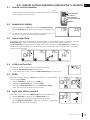
18
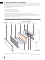
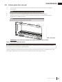
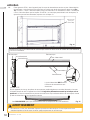
Dynamic Heat Control™
Ceiling
(L illustrated)
Safety Barrier
No screws
in this area.
Stud
!
WARNING
• The Dynamic Heat Control™ system is not available for any appliance from the Acies series (L
models). Do not follow any instructions provided in the “Dynamic Heat Control™ (LV optional / LVX included)”
section if you have an L model. Refer to your appliance installation manual or contact your authorized dealer for
more information. Fire hazard!
• Your appliance, gas/electrical connections, venting and various key components are hidden behind the wall. It
is critical that no screws penetrate the areas illustrated below. Failure to follow instructions may cause improper
operation, damage, personal injury or fi re. Always use a stud fi nder and only screw into studs.
5.0 clearances around fi replace
The temperatures above the
fi replace for L models will
be hot, making it unsuitable
for mounting a TV or other
objects sensitive to heat
above the fi replace without
risk of damage.
Installing a mantel
between this appliance and
electronics or other materials
that may be sensitive to
heat will reduce the effect of
direct heat on them.
The size and material of
the mantel will affect the
allowable clearance above
your fi replace and incorrect
placement could become
a fi re hazard. Consult your
installation manual and/or
authorized dealer for more
information.
Your fi replace, gas/electrical
connections and vent are
hidden directly behind the
fi nished wall. Great care
should be taken to avoid
screwing or nailing into these
components. Always use a
stud fi nder to determine stud
location and only screw into
studs.
Do not screw into the area
around the fi replace opening.
If in doubt, refer to your installation manual and/or contact your authorized dealer.
important:
(Screw restriction applies
to ALL models.)

EN
W415-2036 / A / 10.18.19
19
clearances around fi replace
Dynamic Heat Control™ is a system for managing the heat produced by the appliance at and around the fi replace
opening. The purpose of Dynamic Heat Control™ is to move the heat away from the fi replace to allow it to
circulate more effectively within the living space. By installing the Dynamic Heat Control™, you gain considerable
benefi ts:
• Heat is circulated more consistently throughout the living space increasing comfort in front of the fi replace.
• Increased real world effi ciency as heat is moved into the room rather than retained inside the fi replace
enclosure.
• Complete fl exibility in selection of fi nish materials.
• Ability to place a TV, sound bar or artwork above the fi replace.
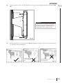
5.1 Dynamic Heat Control™ (LV optional / LVX included)
The Dynamic Heat Control™ system should be installed with the appliance. It is not practical as an upgrade
after installation and fi nishing completed. The Dynamic Heat Control™ system is not available for L models.
note:
DOS
• Screw into studs (see “Dynamic Heat
Control™ (not available for L models”
section).
• Maintain at least the minimum clearances
illustrated.
DON’TS
• Place objects too close to air outlet
• Place objects too close to air inlet.
• Screw into the appliance.
!
WARNING
• When fi tted with DHC, your appliance, gas/electrical connections, venting and various key components are
hidden behind the wall. It is critical that no screws penetrate the areas illustrated below. Failure to follow
instructions may cause improper operation, damage, personal injury or fi re. Always use a stud fi nder and only
screw into studs (see illustration in “Dynamic Heat Control™ (not available for L models)” section).
6” min.
Ceiling
Air inlet (LV models)
Air outlet
(LV illustrated w/ optional DHC)
(LVX illustrated)
Safety Barrier
6” min.
Dynamic Heat
Control™ Air Inlet
(LVX models)
Glass Guard
6” min.
Glass Guard
2” min.
2” min.
6” min.
6” min.
6” min.
6” min.
PATENT PENDING
Image not to scale.

W415-2036 / A / 10.18.19
EN
20
maintenance
6.0 maintenance
!
WARNING
• Turn off the gas and electrical power before servicing the appliance.
• Appliance may be hot. Do not service until appliance has cooled.
For qualifi ed technicians only:
• Label all wires prior to disconnection when servicing controls. Wiring errors can cause improper and dangerous
operation. Verify proper operation after servicing.
• This appliance and its venting system should be inspected before use and at least annually by a qualifi ed service
person.
• The fl ow of combustion and ventilation air must not be obstructed.
DOS
• Clean your glass guard assembly (LVX only)
regularly (see “care of glass” section.) Clean your
safety barrier (L and LV only) or regularly to prevent
the build up of excessive lint/dust from carpeting,
pet hair, etc. Simply vacuum using the brush
attachment.
• Always use ammonia-free glass cleaners.
• Service your appliance annually and/or as
required. Service must be conducted by a qualifi ed
technician.
• Keep your appliance area clear and free of
combustible materials, gasoline, or other fl ammable
vapors and liquids.
• Check to see that the burner ignites completely
on all openings when turned on. A 5 to 10 second
total light-up period is satisfactory. Service as
required.
DON’TS
• Attempt to service the electrical or gas
components. Contact a qualifi ed technician.
• Use excessive force.
• Use abrasive cleaners on glass.
• Paint the pilot assembly.
• Place objects too close to the fi replace opening
(all models) or air inlet and air outlet (LV models
fi tted with optional DHC and LVX models)
For any questions and/or concerns regarding your appliance, maintenance and service, please contact your
authorized dealer.
note:
La page est en cours de chargement...
La page est en cours de chargement...
La page est en cours de chargement...
La page est en cours de chargement...
La page est en cours de chargement...
La page est en cours de chargement...
La page est en cours de chargement...
La page est en cours de chargement...
La page est en cours de chargement...
La page est en cours de chargement...
La page est en cours de chargement...
La page est en cours de chargement...
La page est en cours de chargement...
La page est en cours de chargement...
La page est en cours de chargement...
La page est en cours de chargement...
La page est en cours de chargement...
La page est en cours de chargement...
La page est en cours de chargement...
La page est en cours de chargement...
La page est en cours de chargement...
La page est en cours de chargement...
La page est en cours de chargement...
La page est en cours de chargement...
La page est en cours de chargement...
La page est en cours de chargement...
La page est en cours de chargement...
La page est en cours de chargement...
La page est en cours de chargement...
La page est en cours de chargement...
La page est en cours de chargement...
La page est en cours de chargement...
La page est en cours de chargement...
La page est en cours de chargement...
La page est en cours de chargement...
La page est en cours de chargement...
La page est en cours de chargement...
La page est en cours de chargement...
La page est en cours de chargement...
La page est en cours de chargement...
La page est en cours de chargement...
La page est en cours de chargement...
La page est en cours de chargement...
La page est en cours de chargement...
La page est en cours de chargement...
La page est en cours de chargement...
La page est en cours de chargement...
La page est en cours de chargement...
La page est en cours de chargement...
La page est en cours de chargement...
La page est en cours de chargement...
La page est en cours de chargement...
La page est en cours de chargement...
La page est en cours de chargement...
La page est en cours de chargement...
La page est en cours de chargement...
La page est en cours de chargement...
La page est en cours de chargement...
La page est en cours de chargement...
La page est en cours de chargement...
-
 1
1
-
 2
2
-
 3
3
-
 4
4
-
 5
5
-
 6
6
-
 7
7
-
 8
8
-
 9
9
-
 10
10
-
 11
11
-
 12
12
-
 13
13
-
 14
14
-
 15
15
-
 16
16
-
 17
17
-
 18
18
-
 19
19
-
 20
20
-
 21
21
-
 22
22
-
 23
23
-
 24
24
-
 25
25
-
 26
26
-
 27
27
-
 28
28
-
 29
29
-
 30
30
-
 31
31
-
 32
32
-
 33
33
-
 34
34
-
 35
35
-
 36
36
-
 37
37
-
 38
38
-
 39
39
-
 40
40
-
 41
41
-
 42
42
-
 43
43
-
 44
44
-
 45
45
-
 46
46
-
 47
47
-
 48
48
-
 49
49
-
 50
50
-
 51
51
-
 52
52
-
 53
53
-
 54
54
-
 55
55
-
 56
56
-
 57
57
-
 58
58
-
 59
59
-
 60
60
-
 61
61
-
 62
62
-
 63
63
-
 64
64
-
 65
65
-
 66
66
-
 67
67
-
 68
68
-
 69
69
-
 70
70
-
 71
71
-
 72
72
-
 73
73
-
 74
74
-
 75
75
-
 76
76
-
 77
77
-
 78
78
-
 79
79
-
 80
80


NAPOLEON L38N Le manuel du propriétaire
- Catégorie
- Cheminées
- Taper
- Le manuel du propriétaire
dans d''autres langues
- English: NAPOLEON L38N Owner's manual
Documents connexes
-
NAPOLEON AX36NTE Manuel utilisateur
-
-
NAPOLEON LVX62N2X Manuel utilisateur
-
-
-
-
-
-
-
Autres documents
-
Danby DDEF03813BD13 Le manuel du propriétaire
-
-
-
Danby DDEF02213BD13 Le manuel du propriétaire
-
Continental Fireplaces CBL36NTE-1 Manuel utilisateur
-
 GreenTouch 1164FM-23-202 Guide d'installation
-
-
-
-
Dimplex CAS500 Le manuel du propriétaire
