
PENTAIR.COM
OWNER'S MANUAL
PRO SELF-PRIMING CENTRIFUGAL AND
SPRINKLER PUMPS
P15007 (03-01-2023)
©2023 Pentair. All Rights Reserved.
ENGLISH: 1-30 FRENCH: 31-60 SPANISH: 61-90

2 P15007 (03-01-2023)
TABLE OF CONTENTS
SAFETY INSTRUCTIONS ..................................................................................................3
INSTALLATION ..........................................................................................................4
ELECTRICAL ............................................................................................................6
OPERATIONS ............................................................................................................8
MAINTENANCE ..........................................................................................................9
REPAIR PARTS .........................................................................................................12
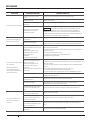
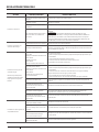
TROUBLESHOOTING .....................................................................................................27
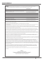
WARRANTIES ..........................................................................................................28
THIS MANUAL COVERS THE FOLLOWING MODEL SERIES:
BERKELEY MODELS: LTHH, BPD, LTH/LTM.
MYERS MODELS: MDPC, QP, PQP.
STA-RITE MODELS: DPC, D, DS2, DS3, PD

3
P15007 (03-01-2023)
SAFETY INSTRUCTIONS
SAFETY SYMBOLS
This is the safety alert symbol. When you see this symbol on
your pump or in this manual, look for one of the following signal
words and be alert to the potential for personal injury:
warns about hazards that will cause serious
personal injury, death or major property damage if ignored.
warns about hazards that can cause serious
personal injury, death or major property damage if ignored.
warns about hazards that will or can cause minor
personal injury or property damage if ignored.
The word NOTE indicates special instructions that are important
but not related to hazards.
CALIFORNIA PROPOSITION 65 WARNING
This product and related accessories contain
chemicals known to the State of California to cause cancer,
birth defects or other reproductive harm.
GENERAL SAFETY
DO NOT TOUCH AN OPERATING MOTOR. Modern
motors can operate at high temperatures. To avoid burns when
servicing pump, allow it to cool for 20 minutes after shut-down
before handling.
To avoid heat buildup, over-pressure hazard, and possible
injury, do not use in a pressure tank (domestic water)
system. Do not use as a booster pump; pressurized suction
may cause pump body to explode.
Do not allow pump or piping system to freeze. Freezing can
damage pump and pipe, may lead to injury from equipment
failure, and will void warranty.
Pump only water with this unit.
Periodically inspect pump and system components.
Wear safety glasses at all times when working on pumps.
Keep work area clean, uncluttered and properly lighted;
properly store all unused tools and equipment.
Keep visitors at a safe distance from the work areas.
Make workshops childproof; use padlocks and master
switches; remove starter keys.
ELECTRICAL SAFETY
Wire motor for correct voltage. See “Electri cal” section of
this manual and motor nameplate.
Ground motor before connecting to power supply.
Meet National Electri cal Code, Canadian Elec tri cal Code,
and local codes for all wiring.
Follow wiring instructions in this manual when connecting
motor to power lines.
Hazardous voltage. Can shock, burn, or
cause death.
Ground pump before connecting to power
supply.

4 P15007 (03-01-2023)
PRIOR TO PUMP INSTALLATION
Ensure the well is not more than 20 foot depth to water.
Locate pump as close to the well as possible, using use as
few elbows and fittings as possible. Long runs and many
fittings increase friction and reduce flow.
Ensure the well is clear of sand. Sand will clog the pump and
void the warranty.
Protect pump and all piping from freezing. Freezing will split
pipe, damage pump and void the warranty. Check local frost
protection requirement. Usually piping must be 12" below
frost line and the pump must be insulated.
Be sure all pipes and the foot valve are clean and in good
shape.
Ensure there are no air pockets or leaks in suction pipe. Use
PTEE pipe thread sealant tape to seal pipe joints.
Unions installed near the well and pump aid in servicing.
Make sure to leave room for use of wrenches.
PUMP BODY MAY EXPLODE if used as a booster
pump. DO NOT use in a booster appli cation.
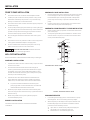
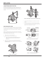
WELL PIPE INSTALLATION
Use the installation method below that matches your well type.
CASED WELL INSTALLATION
1. Inspect foot valve to be sure it works freely. Inspect strainer
to be sure it is clean.
2. Connect foot valve and strainer to the first length of
suction pipe and lower pipe into well. Add sections of pipe
as needed, using PTFE pipe thread sealant tape on male
threads. Be sure that all suction pipe is leak proof or pump
will lose prime and fail to pump.
3. Install foot valve 10 to 20 feet below the lowest level to
which water will drop while pump is operating (pumping
water level). Your well driller can furnish this in formation.
To prevent sand and sediment from entering the
pumping system, the foot valve/strainer should be at
least 5 feet above the bottom of the well.
4. When the proper depth is reached, install a sanitary well
seal over the pipe and in the well casing. Tighten the bolts to
seal the casing.
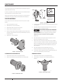
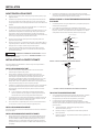
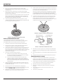
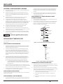
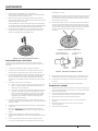
5. When using a foot valve, a priming tee and plug are
recommended (Figure 1).
DUG WELL INSTALLATION
Follow the same instructions as outlined in Cased Well
Installation.
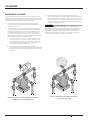
DRIVEN WELL POINT INSTALLATION
1. Connect the suction pipe to the drive point (Figure 2). Keep
horizontal pipe run as short as possible. Use PTFE pipe
thread sealant tape on male pipe threads. Multiple well
points may be necessary to provide sufficient water to
pump.
2. Install a check valve in horizontal pipe. Ensure the check
valve's flow arrow point toward the pump.
HORIZONTAL PIPING FROM WELL TO PUMP INSTALLATION
1. Never install a suction pipe that is smaller than the suction
port of the pump.
2. To aid priming with well point installations, install a check
valve as shown in Figure 2. Ensure the check valve's flow
arrow point toward the pump.
Suction
pipe
Foot
Valve
Priming plug
Priming tee
Drawdown water
level (pump on)
10-20' (3-6 m)
20' (6 m)
max.
At least 5 feet
(1.5 m)
828 1011
Standing water
level (pump off)
FIGURE 1 –
CASED/DUG WELL INSTALLATION
Check valve
Steel drive pipe
Drive coupling
Driven point
745 0993
FIGURE 2 – DRIVEN POINT INSTALLATION
DISCHARGE PIPE SIZES
1. If increasing discharge pipe size, install reducer in pump
discharge port. Do not increase pipe size by stages.
2. When the pump is set away from the points of water use,
the discharge pipe size should be increased to reduce
pressure losses caused by friction.
Up to 100’ run: Same size as pump discharge port.
100’ to 300’ run: Increase one pipe size.
300’ to 600’ run: Increase two pipe sizes.
INSTALLATION

5
P15007 (03-01-2023)
INSTALLATION
20 100
80
60
40
3024 0997
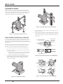
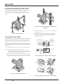
FIGURE 5 – INDEPENDENTLY SUPPORT PIPING ATTACHED TO PUMP
4. Tighten joints hand tight plus 1-1/2 turns. Do not over
tighten.
5. If long, horizontal pipe runs have to be used, install a
priming tee between the check valve and the well head
(Figure 1). Use schedule 80 or iron pipe.
1102 0697
No Air Leaks
in Suction Pipe.
Pipe Joint
Compound Will
Damage Plastic.
If Air Flows
Water Won’t
Use PTFE Tape
FIGURE 6 – NO AIR POCKETS IN SUCTION PIPE
FIGURE 7 – SUCTION PIPE MUST NOT LEAK
LAWN SPRINKLING APPLICATION
This pump is designed for a pond, cistern or well points. Pump
discharge can be divided to supply two (2) or more sprinkler
systems. A suggested multiple dis charge to service is shown in
Figure 3.
20 100
80
60
40
1909 0997
FIGURE 3 – MULTIPLE DISCHARGE
PUMP/PIPING INSTALLATION
Use only pipe thread sealant tape for making all threaded
connections to the pump itself. Do not use pipe joint compounds
on plastic pumps: they can react with the plastic in the pump
components.
Make sure that all pipe joints in the suction pipe are air tight as
well as water tight. If the suction pipe can suck air, the pump will
not be able to pull water from the well.
1. Bolt pump to solid, level foundation.
2. Support all piping connected to the pump.
Install pump as close to well head as poss ible. Long
piping runs and many fittings create friction and
reduce flow.
3. Wrap 1-1/2 to 2 layers of PTFE pipe thread sealant tape
clockwise (as you face end of pipe) on all male threads being
attached to pump.
3023 0997
FIGURE 4 – BOLT PUMP DOWN
748 0993
Don’t Hit
Thread Stops
Don’t
Overtighten
From
Well
Pump
Body
Hand Tight Plus 1-1/2 Tu rns With Wrench.

6 P15007 (03-01-2023)
ELECTRICAL
WIRING
Install, ground, wire and maintain this pump in accordance
with electrical code requirements. Consult your local building
inspector for information about codes. Read and follow all
warnings below.
HAZARDOUS VOLTAGE. Can shock, burn or kill.
Disconnect power to motor before working on pump or motor.
Ground motor before connecting to power supply.
To avoid dangerous or fatal electrical shock, turn OFF power
to motor before working on electrical connections.
Supply voltage must be within ±10% of nameplate voltage.
Incorrect voltage can cause fire or damage motor and voids
warranty. If in doubt consult a licensed electrician.
Use wire size specified in this manual's Wiring Chart.
Wire motor according to diagram on motor nameplate. If
nameplate diagram differs from this manual's diagrams, follow
nameplate diagram.
1. Provide a correctly fused disconnect switch for protection
while working on motor. Consult local or national electrical
codes for switch requirements*.
2. Disconnect power before servicing motor or pump. If the
disconnect switch is out of sight of pump, lock it open and
tag it to prevent unexpected power application.
3. Ground the pump permanently using a wire of the same size
as specified in this manual's Wiring Chart. Make ground
connection to green grounding terminal under motor
canopy marked GRD. or .
4. Connect ground wire to a grounded lead in the service
panel or to a metal underground water pipe or well casing
at least 10 feet long. Do not connect to plastic pipe or
insulated fittings.
Do not ground to a gas supply line.
5. Protect current carrying and grounding conductors from
cuts, grease, heat, oil, and chemicals.
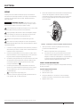
6. Motor has automatic internal thermal overload protection.
If motor has stopped for unknown reasons, thermal
overload may restart it unexpectedly, which could cause
injury or property damage. Disconnect power before
servicing motor.
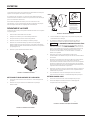
Voltage
Change Dial
Ground
Screw
Power Lead
Te rminals
4695
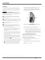
FIGURE 8 - VOLTAGE SET TO 230 VOLT CURRENT. ROTARY SELECTOR
7. If this procedure or the wiring diagram are confusing,
consult a licensed electrician
Refer to Figure 8 for wiring configuration.
Connect current-carrying conductors to terminals
L1 and L2. When replacing the motor, check wiring
diagram on the motor nameplate. For 3-phase motors
or motor's whose wiring diagram does not match
Figure 8, follow the diagram on the motor.
115 VOLT USAGE CONFIGURATION
115/230 volt, single phase models are configured at the factory
for 230 volt usage.
If power supply will be 115 volts:
1. Ensure power is off.
2. Remove motor cover.
3. Using a screwdriver or 1/2" wrench, turn the voltage
selector dial counter-clockwise to the 115 volt setting.
4. Replace motor cover.
(*) Dual element or Fusetron time delay fuses recommended for all motor circuits.

7
P15007 (03-01-2023)
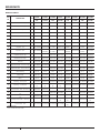
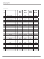
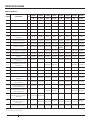
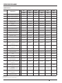
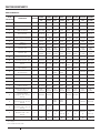
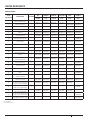
ELECTRICAL
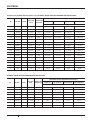
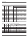
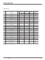
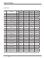
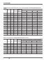
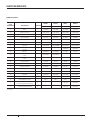
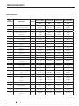
HP VOLTAGE PHASE MAX. LOAD
AMPS
BRANCH FUSE
RATING AMP
DISTANCE IN FEET (METERS) FROM MOTOR TO SUPPLY
0-100 (0-30) 101-200 (31-61) 201-300 (62-91) 301-400 (92-122)
AWG WIRE SIZE - 115V/230V (MM
2
)
1/2 115/230 18.5/4.3 15/15 14/14 (2/2) 12/14 (3/2) 10/14 (5.5/2) 8/14 (8.4/2)
3/4 115/230 111.4/5.7 20/15 14/14 (2/2) 10/14 (5.5/2) 8/14 (8.4/2) 6/12 (14/3)
1115/230 112.2/6.1 25/15 12/14 (3/2) 8/14 (8.4/2) 8/14 (8.4/2) 6/12 (14/3)
1230/460 33.6/1.8 15/15 14/14 (2/2) 14/14 (2/2) 14/14 (2/2) 14/14 (2/2)
1-1/2 115/230 118.4/9.2 30/20 10/14 (5.5/2) 8/14 (8.4/2) 6/12 (14/3) 4/10 (21/5.5)
1-1/2 230/460 3 4.7/2.35 15/15 14/14 (2/2) 14/14 (2/2) 14/14 (2/2) 14/14 (2/2)
2115/230 122.8/11.4 45/25 10/14 (5.5/2) 6/12 (14/3) 6/12 (14/3) 4/10 (21/5.5)
2230/460 36.8/3.4 15/15 14/14 (2/2) 14/14 (2/2) 12/14 (3/2) 12/14 (3/2)
2-1/2 115/230 122/11 45/25 10/14 (5.5/2) 8/12 (8.4/3) 6/12 (14/3) 4/10 (21/5.5)
2-1/2 230/460 3 8.5/4.25 15/15 14/14 (2/2) 14/14 (2/2) 12/14 (3/2) 10/14 (5.5/2)
3230 117 25 12 (3) 12 (3) 10 (5.5) 8 (8.4)
3230/460 39.6/4.8 15/15 14/14 (2/2) 14/14 (2/2) 12/14 (3/2) 12/14 (3/2)
3200 311 15 14 (2) 14 (2) 12 (3) 10 (5.5)
5230 128 40 8 (8.4) 8 (8.4) 8 (8.4) 6 (14)
5200 132.2 50 8 (8.4) 8 (8.4) 8 (8.4) 6 (14)
5230/460 315.2/7.6 20/15 12/14 (3/2) 12/14 (3/2) 10/14 (5.5/2) 10/14 (5.5/2)
5200 317.5 25 10 (5.5) 10 (5.5) 10 (5.5) 8 (8.4)
DS2, DS3, LTHH, PD, BPDH, PQP, DPC, MDPC, D, LTH, LTM SERIES - WIRING CHART RECOMMENDED WIRE AND FUSE SIZES
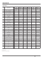
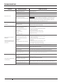
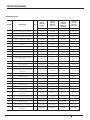
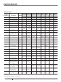
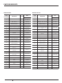
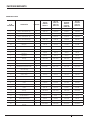
HP VOLTAGE PHASE MAX. LOAD
AMPS
BRANCH FUSE
RATING AMP
DISTANCE IN FEET (METERS) FROM MOTOR TO SUPPLY
0-100 (0-30) 101-200 (31-61) 201-300 (62-91) 301-400 (92-122)
AWG WIRE SIZE - 115V/230V (MM
2
)
3/4 115/230 114.8/7.4 20/15 12/14 (3/2) 8/14 (8.4/2) 6/14 (14/2) 6/12 (14/3)
1115/230 118.6/9.3 30/20 10/14 (5.5/2) 8/14 (8.4/2) 6/12 (14/3) 4/10 (21/5.5)
1-1/2 115/230 122.0/11.0 45/25 10/14 (5.5/2) 8/12 (8.4/3) 6/12 (14/3) 4/10 (21/5.5)
2115/230 122.6/11.3 45/25 10/14 (5.5/2) 6/12 (14/3) 6/12 (14/3) 4/10 (21/5.5)
2230/460 38.6/4.3 20/10 14/14 (2/2) 14/14 (2/2) 12/14 (3/2) 12/14 (3/2)
3208-230 115.0-13.3 35 12 (3) 12 (3) 10 (5.5) 8 (8.4)
5230 125.4 60 8(8.4) 8(8.4) 8(8.4) 8(8.4)
5230/460 311.8/5.9 15 14/14 (2/2) 14/14 (2/2) 12/14 (3/2) 10/14 (5.5/2)
QP SERIES - WIRING CHART RECOMMENDED WIRE AND FUSE SIZES

8 P15007 (03-01-2023)
OPERATIONS
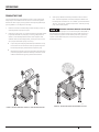
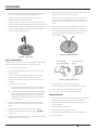
PRIMING THE PUMP
Priming refers to the pump expelling all air in the system and
beginning to move water from its source out into the system.
It does not refer only to pouring water into the pump (although
pouring water in is usually the first step).
1. Make sure suction and discharge valves and any hoses on
discharge side of pump are open.
2. Remove priming plug. Fill pump and suction pipe with water
(Figure 9). NEVER run pump dry. Running pump without
water in it will damage seals and can melt impeller and
diffuser. Be sure discharge (valve, pistol grip hose nozzle,
etc.) is open whenever pump is running.
If a priming tee and plug have been provided for a long
horizontal run, be sure to fill suction pipe through this
tee and replace plug. Remember to tape the plug.
Replacing the existing priming plug with one that has a
pressure gauge and reducer bushing mounted in it will
make troubleshooting pump performance easier.
3. Start pump. Water should be produced in 10 minutes or
less. The time depends on the well's depth to water and
the length of horizontal run. If no water is produced within
10 mins., stop pump, release all pressure, remove priming
plug, refill, and try again.
HAZARDOUS PRESSURE AND RISK OF EX PLO SION
AND SCALDING. If pump is run con ti nu ously at no flow (that is,
with discharge shut off or without priming), water may boil in
pump and piping system. Under steam pressure, pipes may
rupture, blow off of fittings or blow out of pump ports and
scald anyone near.
20 100
80
60
40
3025 0997
FIGURE 9 – REMOVE PRIMING PLUG AND FILL PUMP BEFORE STARTING
20 100
80
60
40
3026 0997
FIGURE 10 – DO NOT RUN PUMP WITH DISCHARGE SHUT-OFF

9
P15007 (03-01-2023)
MAINTENANCE
The pump and piping do not need to be disconnected to repair or
replace the motor or seal.
If motor is replaced, a new shaft seal must be installed. Keep an
extra shaft seal on hand for future needs.
Check motor label for lubrication instructions. The mechanical
shaft seal in the pump is water lubricated and self-adjusting.
PUMP DISASSEMBLY
Drain pump when disconnecting from service or when it might
freeze.
1. Disconnect power to motor.
2. Mark wires for correct assembly.
3. Release all water pressure from system.
4. Remove drain plug and drain pump.
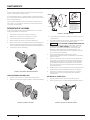
5. Remove cap screws holding seal plate to pump body. Motor
assembly and seal plate can now be pulled away from pump
body (Figure 11).
6. CARE FULLY remove gasket.
3027 0997
FIGURE 11 – SLIDE MOTOR BACK
CLEANING/REPLACING IMPELLER
1. Follow instructions under “Pump Dis assembly”.
2. Remove screws fastening the diffuser to the seal plate.
3028 0997
FIGURE 12 – REMOVE DIFFUSER
FIGURE 13 – HOLD SHAFT
To avoid electrical
shock hazard, use
insulated-handle
screwdriver to short
capacitor terminals
as shown.
3. Remove diffuser (Figure 12). The exposed impeller can now
be cleaned.
4. If impeller must be replaced, loosen two machine screws
and remove motor canopy (Figure 13).
5. CAPACITOR VOLTAGE MAY BE HAZARDOUS.
To discharge capacitor, hold insulated handle screwdriver
BY THE HANDLE and short capacitor terminals together
(Figure 13). Do not touch metal screwdriver blade or
capacitor terminals. If in doubt, consult a qualified
electrician.
6. Unscrew capacitor clamp and remove capacitor. Do not
disconnect capacitor wires to motor.
7. Slide a 7/16" open-end wrench behind the spring-loaded
switch on the motor end of the shaft. Hold motor shaft with
wrench on shaft flats and unscrew impeller screw (if used)
by turning clockwise (left hand thread) when looking into
eye of impeller.
8. Unscrew impeller while holding shaft by turning
counterclockwise while looking into eye of impeller.
9. To reinstall, reverse steps 1 through 6 and follow directions
in the "Pump Reassembly" section below.
REMOVING OLD SEAL
1. Follow instructions under “Pump Disassembly”.
2. Follow steps 2 through 5 under “Cleaning/Replacing
Impeller”.
3029 0997
FIGURE 14 – REMOVE SEAL PLATE

10 P15007 (03-01-2023)
MAINTENANCE
3. Remove rotating half of seal by placing two screw drivers
under seal ring and carefully prying up (Figure 14).
4. Remove nuts from studs holding seal plate to motor.
Carefully slide seal plate off of shaft.
Be sure you do not scratch or mar shaft. If shaft is marred,
it must be dressed smooth with fine emery or crocus cloth
before installing new seal. DO NOT reduce shaft diameter!
5. Place seal plate half face down on flat surface and tap out
stationary half of seal (Figure 15).
3030 0997
FIGURE 15 – TAP OUT SEAL
INSTALLING NEW SEAL
Gaskets and o-rings are not interchangeable per models. Make
sure to install the type of gasket or o-ring you removed.
1. Clean seal cavity in seal plate.
2. Sparingly wet outer edge of rubber cup on ceramic seat
with liquid soap.
3. Put clean cardboard washer on seal face. The ceramic
seal's polished face should be facing up. Firmly and
squarely, press ceramic seal into cavity using only hand
pressure.
4. If seal will not seat correctly:
Remove seal, placing polished side up on bench. Re-
clean cavity and install as outlined in previous step.
If seal still does not seat properly after re-cleaning the
cavity, place a cardboard washer over polished seal
face and carefully press into place using a piece of
standard 3/4 inch pipe as a press being careful not to
scratch seal face."
5. Dispose of cardboard washer and recheck seal face to
be sure it is free of dirt, foreign particles, scratches and
grease.
6. Inspect shaft to be sure it is free of nicks and scratches.
7. Reassemble pump body half to motor flange. BE SURE it is
right side up.
8. Apply liquid soap sparingly (one drop is sufficient) to inside
diameter of rotating seal member.
9. Slide rotating seal member (carbon face first) onto shaft
until rubber drive ring hits shaft shoulder.
Be sure not to nick or scratch carbon face of seal when
passing it over threaded shaft end or shaft shoulder. The
carbon surface must remain clean or short seal life will
result.
10. Hold motor shaft with 7/16” open end wrench on shaft
flats and screw impeller onto shaft. Be sure you do not
touch capacitor terminals with body or any metal object.
Tightening impeller will automatically locate seal in
correct position.
3031 0997
FIGURE 16 – PRESS IN NEW SEAL
1072 0697
Ceramic
Face Carbon
Face
Be Careful That
Motor Shaft Shoulder...
...Does Not Damage
Seal Face
FIGURE 17 – PROTECT SEAL FACES
11. Replace impeller screw (if used) by turning
counterclockwise (left-hand thread) into end of shaft.
12. Remount diffuser on seal plate with two screws.
13. Follow instructions under “Pump Reassembly”.
PUMP REASSEMBLY
1. Install new gasket or O-ring. Note to replace with using the
same as the pump was originally manufactured with.
2. Slide motor/seal plate assembly into pump body. Secure
with cap screws.
3. Replace base mounting bolts.
4. Replace motor wiring; close drain cock.
5. Prime pump according to instructions. See “Opera tion.”
6. Check for leaks.

11
P15007 (03-01-2023)
PAGE INTENTIONALLY LEFT BLANK

12 P15007 (03-01-2023)
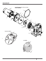
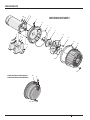
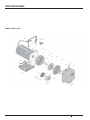
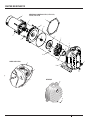
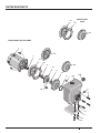
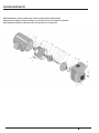
REPAIR PARTS
2419A 0605
1
2
3
14
13
6
7B
10
12
11
5
6
7
8
6A
4a
9
4
DS2 SERIES AND LTH-1, LTH-1-1/2, LTH-2,
LTH-2-1/2 MODELS
9
12
12
11
DS3/LTHH SERIES
10
12
QP SERIES

13
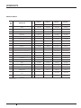
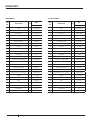
P15007 (03-01-2023)
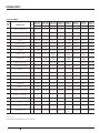
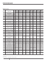
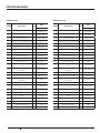
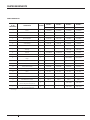
KEY
NO. DESCRIPTION QTY
S40058/
S40061
S40063/
S40065
S40067/
S40069 S40071 10LTHH/
10LTHH3
15LTHH/
15LTHH3
20LTHH/
20LTHH3
25LTHH/
25LTHH3
1 HP 1-1/2 HP 2 HP 2-1/2 HP 1 HP 1-1/2 HP 2 HP 2-1/2 HP
1 Motor - 115/230V, 1ph 1 J218-1653 J218-1655 J218-1656 J218-1657 J218-1653 J218-1655 J218-1656 J218-1657
1 Motor - 230/460V, 3ph 1 AP100EL AP100FL AP100GL AP100G5L AP100EL AP100FL AP100GL AP100G5L
2Water Slinger 117351-0009 17351-0009 17351-0009 17351-0009 17351-0009 17351-0009 17351-0009 17351-0009
3 Seal Plate 1 C3-155-SR C3-155-SR C3-117 C3-117 C3-155-SR C3-155-SR C3-117 C3-117
4 Seal Plate Gasket 1 C20-86N C20-86N C20-87N C20-87N C20-86N C20-86N C20-87N C20-87N
4A Seal Plate O-Ring 1 25276 25276 34516 34516 25276 25276 34516 34516
5Shaft Seal 1U109-6B U109-6B U109-6B U109-6B U109-6B U109-6B U109-6B U109-6B
6Impeller - 1ph 1C105-92PKB C105-92PCB C105-
214PDA C105-214PA C105-
92PKB C105-92PC C105-
214PDA C105-214PA
6Impeller - 3ph 1C105-92PKBA C105-
92PCBA
C105-
214PDA C105-214PA C105-
92PKBA C105-92PCA C105-
214PDA C105-214PA
6A Impeller Screw - 1ph 1 - - C30-14SS C30-14SS - - C30-14SS C30-14SS
6A Impeller Screw - 3ph 1 C30-14SS C30-14SS C30-14SS C30-14SS C30-14SS C30-14SS C30-14SS C30-14SS
7Diffuser 1C101-276P C101-276P C101-182 C101-182 C101-276P C101-276P C101-182 C101-182
7A Diffuser Screws - 1/4 - 20 x 1" Lg. 2 U30-696SS U30-696SS - - U30-696SS U30-696SS - -
7A Diffuser Screws - 8 - 32 x 7/8" Lg. 2 - - U30-53SS U30-53SS - - U30-53SS U30-53SS
8Diffuser Ring 1C21-10 C21-10 C21-2 C21-2 C21-10 C21-10 C21-2 C21-2
9Pump Body 1C76-49B C76-49B C76-50 C76-50 C76-67E C76-67E C76-68E C76-68E
10 Base 1U4-5 U4-5 U4-5 U4-5 C4-82 C4-82 C4-82 C4-82
11 Pipe Plug - 3/4" Sq. Hd. 1 U78-60ZPS U78-60ZPS U78-60ZPS U78-60ZPS U78-60ZPS U78-60ZPS U78-60ZPS U78-60ZPS
12 Pipe Plug - 1/4" Hex Hd. 2 U78-941ZPV
(1)
U78-941ZPV
(1)
U78-941ZPV
(1)
U78-941ZPV
(1) U78-941ZPV U78-941ZPV U78-941ZPV U78-941ZPV
13 Hex Cap screw - 3/8" - 16 x 3/4" Lg. 8 U30-72ZP U30-72ZP - - U30-72ZP U30-72ZP - -
13 Hex Cap screw - 5/16" - 18 x 3/4"
Lg. 8 - - U30-60ZP U30-60ZP - - U30-60ZP U30-60ZP
14 Hex Cap screw - 3/8 " - 16 x 1-1/4"
Lg. ( ) U30-75ZP (4) U30-75ZP (4) - - - - - -
14 Hex Cap screw - 3/8 " - 16 x 1" Lg. ( ) - U30-74ZP (4) U30-74ZP (4) U30-74ZP**
(4)
U30-74ZP
(2) U30-74ZP (2) U30-74ZP (4) U30-74ZP**
(4)
* Lock washer - 3/8" ( ) U43-12ZP (8) U43-12ZP (8) U43-12ZP (8) U43-12ZP (8) U43-12ZP
(2) U43-12ZP (2) U43-12ZP (2) U43-12ZP (2)
REPAIR PARTS
* Not pictured
** 25LTHH3 uses U30-99S
BERKELEY MODELS

14 P15007 (03-01-2023)
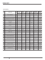
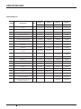
KEY
NO. DESCRIPTION QTY QP7 QP10-01/
QP10B-01
QP15-01/
QP15B-01 QP20/ QP20-3 QP30 QP50B/
QP50B-3
3/4 HP 1 HP 1-1/2 HP 2 HP 3 HP 5 HP
1 Motor - 115/230V, 1ph 1 20934A000-
BK-KT
20935A000-BK-
01-KT
20589A000-BK-
01-KT
20591A000-
BK-KT - -
1 Motor - 230V, 1ph 1 - - - - 20592A000K 26579A000
1 Motor - 230/460V, 3ph 1 - - - 20596A000K -C218-182BD-01
2Water Slinger 117351-0009 17351-0009 17351-0009 17351-0009 17351-0009 S12260
3Bracket 120598D100W 20598D100W 20598D100W 20598D100W 20598D100W 26545E000
4Bracket Gasket 105014A167 05014A167 05014A167 05014A167 05014A167 -
4A Bracket O-Ring 1 - - - - - 05876A138
5Shaft Seal 114525A000K 14525A000K 14525A000K 14525A000K 14525A000K 21181A016K
6Impeller - Composite 1 - 20600B003 20601B003 ---
6Impeller - Brass 120599B000K 20600B000K 20601B000K 20602B000K 20603B000K 26546C000
6A Impeller Nut - Brass Impellers 1U36-33SS U36-33SS U36-33SS U36-33SS U36-33SS 26583A000
7Diffuser 120559D000K 20559D000K 20560D000K 20560D000K 20561D000K 26547D000
7A Diffuser Screws - 1/4 - 20 x 1-1/2"
Lg. 319099A014 19099A014 19099A014 19099A014 19099A014 -
7A Diffuser Screws - 1/2 - 20 x 1-3/4"
Lg. 3 - - - - - 19099A022
8Diffuser Ring 105014A166 05014A166 05014A166 05014A166 05014A166 05876A059
9Pump Body 120604D100W 20604D100W 20604D100W 20604D100W 20604D100W 26544D000
10 Base 1 - - - - - 26579B000
11 Pipe Plug - 3/4" Sq. Hd. 1 - - - - - -
12 Pipe Plug - 1/4" Hex Hd. 1 U78-941ZPV U78-941ZPV U78-941ZPV U78-941ZPV U78-941ZPV U78-941ZPV
13 Hex Cap Screw - 7/16 - 14 x 1-1/2"
Lg. 419102A012 19102A012 19102A012 19102A012 19102A012 -
13 Hex Cap Screw - 3/8" - 16 x 1-3/4"
Lg. 4 - - - - - S23625
14 Hex Cap Screw - 3/8 " - 16 x 7/8"
Lg. 4U30-73ZP U30-73ZP U30-73ZP U30-73ZP U30-73ZP -
14 Hex Cap Screw - 3/8 " - 16 x 1-1/4"
Lg. 4 - - - - - U30-74ZP
* Lockwasher - 3/8" 4 - - - - - U43-12ZP**
REPAIR PARTS
* Not pictured
** QP50B-3 uses quantity 8
MYERS MODELS

15
P15007 (03-01-2023)
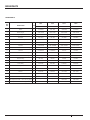
REPAIR PARTS
KEY
NO. DESCRIPTION QTY
DS2HE-191PL/
DS2HE3-191P
DS2HF-192PL/
DS2HF3-192P
DS2HG-102L/
DS2HG3-102
DS2HHG-53L/
DS2HHG3-53
DS3HE-01/
DS3HE3-01
DS3HF-01/
DS3HF3-01
DS3HG-01/
DS3HG3-01
DS3HHG-01/
DS3HHG3-01
1 HP 1-1/2 HP 2 HP 2-1/2 HP 1 HP 1-1/2 HP 2 HP 2-1/2 HP
1 Motor - 115/230V, 1ph 1 J218-1653 J218-1655 J218-1656 J218-1657 J218-1653 J218-1655 J218-1656 J218-1657
1 Motor - 230/460V, 3ph 1 AP100EL AP100FL AP100GL AP100G5L AP100EL AP100FL AP100GL AP100G5L
2Water Slinger 117351-0009 17351-0009 17351-0009 17351-0009 17351-0009 17351-0009 17351-0009 17351-0009
3 Seal Plate 1 C3-155-SR C3-155-SR C3-117 C3-117 C3-155-SR C3-155-SR C3-117 C3-117
4 Seal Plate Gasket 1 C20-86N C20-86N C20-87N C20-87N C20-86N C20-86N C20-87N C20-87N
4A Seal Plate O-Ring 1 25276 25276 34516 34516 25276 25276 34516 34516
5Shaft Seal 1U109-6B U109-6B U109-6B U109-6B U109-6B U109-6B U109-6B U109-6B
6Impeller - 1ph 1C105-92PKB C105-92PCB C105-
214PDA C105-214PA C105-
92PKB C105-92PC C105-
214PDA C105-214PA
6Impeller - 3ph 1C105-92PKBA C105-
92PCBA
C105-
214PDA C105-214PA C105-
92PKBA C105-92PCA C105-
214PDA C105-214PA
6A Impeller Screw - 1ph 1 - - C30-14SS C30-14SS - - C30-14SS C30-14SS
6A Impeller Screw - 3ph 1 C30-14SS C30-14SS C30-14SS C30-14SS C30-14SS C30-14SS C30-14SS C30-14SS
7Diffuser 1C101-276P C101-276P C101-182 C101-182 C101-276P C101-276P C101-182 C101-182
7A Diffuser Screws - 1/4 - 20 x 1" Lg. 2 U30-696SS U30-696SS - - U30-696SS U30-696SS - -
7A Diffuser Screws - 8 - 32 x 7/8" Lg. 2 - - U30-53SS U30-53SS - - U30-53SS U30-53SS
8Diffuser Ring 1C21-10 C21-10 C21-2 C21-2 C21-10 C21-10 C21-2 C21-2
9Pump Body 1C76-49B C76-49B C76-50 C76-50 C76-67E C76-67E C76-68E C76-68E
10 Base 1U4-5 U4-5 U4-5 U4-5 C4-82 C4-82 C4-82 C4-82
11 Pipe Plug - 3/4" Sq. Hd. 1 U78-60ZPS U78-60ZPS U78-60ZPS U78-60ZPS U78-60ZPS U78-60ZPS U78-60ZPS U78-60ZPS
12 Pipe Plug - 1/4" Hex Hd. ( ) U78-941ZPV
(1)
U78-941ZPV
(1)
U78-941ZPV
(1)
U78-941ZPV
(1)
U78-941ZPV
(2)
U78-941ZPV
(2)
U78-941ZPV
(2)
U78-941ZPV
(2)
13 Hex Cap screw - 3/8" - 16 x 3/4" Lg. 6 U30-72ZP U30-72ZP - - U30-72ZP U30-72ZP - -
13 Hex Cap Screw - 5/16" - 18 x 3/4"
Lg. 8 - - U30-60ZP U30-60ZP - - U30-60ZP U30-60ZP
14 Hex Cap Screw - 3/8 " - 16 x 1" Lg. ( ) U30-74ZP (4) U30-74ZP (4) U30-74ZP (4) U30-74ZP**
(4)
U30-74ZP
(2) U30-74ZP (2) U30-74ZP (4) U30-74ZP**
(4)
* Lock washer - 3/8" ( ) U43-12ZP (8) U43-12ZP (8) U43-12ZP (8) U43-12ZP (8) U43-12ZP
(2) U43-12ZP (2) U43-12ZP (2) U43-12ZP (2)
STA-RITE MODELS
* Not pictured
** DS2HHG3-53L and DS3HHG3-01 uses U30-99S

16 P15007 (03-01-2023)
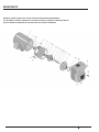
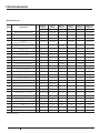
REPAIR PARTS
L
1
7
6
-
3
5
P
12
3
4
5
6
7
8
9
11
12
13
10
14
15
15
16
16
17
12
3
13
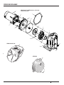
PDHG/BPDH20/PQP20 MODELS
PDHHG/BPDH25/PQP25 MODELS
PD2HE/BPDH10/PQP10 MODELS
PD2HF/BPDH15/PQP15 MODELS

17
P15007 (03-01-2023)
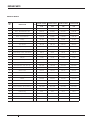
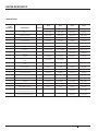
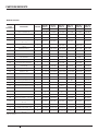
REPAIR PARTS
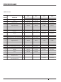
KEY
NO. DESCRIPTION QTY BPDH10-L BPDH15-L BPDH20-L BPDH25-L
1 HP 1-1/2 HP 2 HP 2-1/2 HP
1Motor 1J218-1653 J218-1655 J218-1656 J218-1657
2Water Slinger 117351-0009 17351-0009 17351-0009 17351-0009
3 Priming Plug - 1/2" NPT 1 WC78-39T WC78-39T WC78-39T WC78-39T
4 Seal Plate 1 L176-47P1 L176-47P1 C3-189P1 C3-189P1
5 Seal Plate O-Ring 1 U9-399 U9-399 U9-228A U9-228A
6Shaft Seal 1U109-6B U109-6B U109-6B U109-6B
7Impeller 1C105-92PVB C105-92PBBB C105-214PFA C105-214PGA
* Impeller Screw - 1/4" - 20 x 1-1/4" Lg. 1 - - C30-51SS C30-51SS
8Diffuser 1C1-258PCA C1-258PCA C1-274P C1-274P
9 Diffuser Screws - 1/4 - 20 x 1" Lg. 4 U30-997SS U30-997SS - -
9 Diffuser Screws - 8 - 32 X 7/8" Lg. 2 - - U30-996SS U30-996SS
10 Diffuser Ring 1U9-226 U9-226 U9-393 U9-393
11 "V" Clamp 1 C19-54SS C19-54SS C19-37A C19-37A
12 Pump Body 1C176-66P C176-66P C176-62P C176-62P
13 Drain Plug - 1/4" NPT 1 WC78-40T WC78-40T
14 Base 1C4-42P C4-42P C4-42P C4-42P
15 Washer 2U43-61ZP U43-61ZP U43-42SS U43-42SS
16 Nut 4U36-37ZP U36-37ZP - -
17 Rubber Pad 1C35-11 C35-11 C35-11 C35-11
*Hex Cap Screw - 3/8 " - 16 x 1-3/4" Lg.
(Top) 2 - - U30-77SS U30-77SS
*Hex Cap Screw - 3/8 " - 16 x 1" Lg.
(Bottom) 2 - - U30-74SS U30-74SS
BERKELEY MODELS
* Not pictured

18 P15007 (03-01-2023)
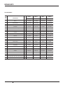
REPAIR PARTS
KEY
NO. DESCRIPTION QTY PQP10 PQP15 PQP20 PQP25
1 HP 1-1/2 HP 2 HP 2-1/2 HP
1Motor 1J218-1653 J218-1655 J218-1656 J218-1657
2Water Slinger 117351-0009 17351-0009 17351-0009 17351-0009
3 Priming Plug - 1/2" NPT 1 WC78-39T WC78-39T WC78-39T WC78-39T
4 Seal Plate 1 L176-47P1 L176-47P1 C3-189P1 C3-189P1
5 Seal Plate O-Ring 1 U9-399 U9-399 U9-228A U9-228A
6Shaft Seal 1U109-6B U109-6B U109-6B U109-6B
7Impeller 1C105-92PVB C105-92PBBB C105-214PFA C105-214PGA
* Impeller Screw - 1/4" - 20 x 1-1/4" Lg. 1 - - C30-51SS C30-51SS
8Diffuser 1C1-258PCA C1-258PCA C1-274P C1-274P
9 Diffuser Screws - 1/4 - 20 x 1" Lg. 4 U30-997SS U30-997SS - -
9 Diffuser Screws - 8 - 32 X 7/8" Lg. 2 - - U30-996SS U30-997SS
10 Diffuser Ring 1U9-226 U9-226 U9-393 U9-393
11 "V" Clamp 1 C19-54SS C19-54SS C19-37A C19-37A
12 Pump Body 1C176-53P C176-53P C176-62P C176-62P
13 Drain Plug - 1/4" NPT 1 WC78-40T WC78-40T
14 Base 1C4-42P C4-42P C4-42P C4-42P
15 Washer 2U43-61ZP U43-61ZP U43-42SS U43-42SS
16 Nut 4U36-37ZP U36-37ZP - -
17 Rubber Pad 1C35-11 C35-11 C35-11 C35-15
* Hex Cap Screw - 3/8 " - 16 x 1-3/4" Lg. (Top) 2 - - U30-77SS U30-77SS
* Hex Cap Screw - 3/8 " - 16 x 1" Lg. (Bottom) 2 - - U30-74SS U30-74SS
MYERS MODELS
* Not pictured

19
P15007 (03-01-2023)
REPAIR PARTS
KEY
NO. DESCRIPTION QTY PD2HE-L PD2HF-L PDHG-L PDHHG-L
1 HP 1-1/2 HP 2 HP 2-1/2 HP
1Motor 1J218-1653 J218-1655 J218-1656 J218-1657
2Water Slinger 117351-0009 17351-0009 17351-0009 17351-0009
3 Priming Plug - 1/2" NPT 1 WC78-39T WC78-39T WC78-39T WC78-39T
4 Seal Plate 1 L176-47P1 L176-47P1 C3-189P1 C3-189P1
5 Seal Plate O-Ring 1 U9-399 U9-399 U9-228A U9-228A
6Shaft Seal 1U109-6B U109-6B U109-6B U109-6B
7Impeller 1C105-92PVB C105-92PBBB C105-214PFA C105-214PGA
* Impeller Screw - 1/4" - 20 x 1-1/4" Lg. 1 - - C30-51SS C30-51SS
8Diffuser 1C1-258PCA C1-258PCA C1-274P C1-274P
9 Diffuser Screws - 1/4 - 20 x 1" Lg. 4 U30-997SS U30-997SS - -
9 Diffuser Screws - 8 - 32 X 7/8" Lg. 2 - - U30-996SS U30-996SS
10 Diffuser Ring 1U9-226 U9-226 U9-393 U9-393
11 "V" Clamp 1 C19-54SS C19-54SS C19-37A C19-37A
12 Pump Body 1C176-66P C176-66P C176-62P C176-62P
13 Drain Plug - 1/4" NPT 1 WC78-40T WC78-40T
14 Base 1C4-42P C4-42P C4-42P C4-42P
15 Washer 2U43-61ZP U43-61ZP U43-42SS U43-42SS
16 Nut 4U36-37ZP U36-37ZP - -
17 Rubber Pad 1C35-11 C35-11 C35-11 C35-11
* Hex Cap Screw - 3/8 " - 16 x 1-3/4" Lg. (Top) 2 - - U30-77SS U30-77SS
* Hex Cap Screw - 3/8 " - 16 x 1" Lg. (Bottom) 2 - - U30-74SS U30-74SS
STA-RITE MODELS
* Not pictured

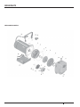
20 P15007 (03-01-2023)
REPAIR PARTS
MDPC AND DPC MODELS
La page charge ...
La page charge ...
La page charge ...
La page charge ...
La page charge ...
La page charge ...
La page charge ...
La page charge ...
La page charge ...
La page charge ...
La page charge ...
La page charge ...
La page charge ...
La page charge ...
La page charge ...
La page charge ...
La page charge ...
La page charge ...
La page charge ...
La page charge ...
La page charge ...
La page charge ...
La page charge ...
La page charge ...
La page charge ...
La page charge ...
La page charge ...
La page charge ...
La page charge ...
La page charge ...
La page charge ...
La page charge ...
La page charge ...
La page charge ...
La page charge ...
La page charge ...
La page charge ...
La page charge ...
La page charge ...
La page charge ...
La page charge ...
La page charge ...
La page charge ...
La page charge ...
La page charge ...
La page charge ...
La page charge ...
La page charge ...
La page charge ...
La page charge ...
La page charge ...
La page charge ...
La page charge ...
La page charge ...
La page charge ...
La page charge ...
La page charge ...
La page charge ...
La page charge ...
La page charge ...
La page charge ...
La page charge ...
La page charge ...
La page charge ...
La page charge ...
La page charge ...
La page charge ...
La page charge ...
La page charge ...
La page charge ...
-
 1
1
-
 2
2
-
 3
3
-
 4
4
-
 5
5
-
 6
6
-
 7
7
-
 8
8
-
 9
9
-
 10
10
-
 11
11
-
 12
12
-
 13
13
-
 14
14
-
 15
15
-
 16
16
-
 17
17
-
 18
18
-
 19
19
-
 20
20
-
 21
21
-
 22
22
-
 23
23
-
 24
24
-
 25
25
-
 26
26
-
 27
27
-
 28
28
-
 29
29
-
 30
30
-
 31
31
-
 32
32
-
 33
33
-
 34
34
-
 35
35
-
 36
36
-
 37
37
-
 38
38
-
 39
39
-
 40
40
-
 41
41
-
 42
42
-
 43
43
-
 44
44
-
 45
45
-
 46
46
-
 47
47
-
 48
48
-
 49
49
-
 50
50
-
 51
51
-
 52
52
-
 53
53
-
 54
54
-
 55
55
-
 56
56
-
 57
57
-
 58
58
-
 59
59
-
 60
60
-
 61
61
-
 62
62
-
 63
63
-
 64
64
-
 65
65
-
 66
66
-
 67
67
-
 68
68
-
 69
69
-
 70
70
-
 71
71
-
 72
72
-
 73
73
-
 74
74
-
 75
75
-
 76
76
-
 77
77
-
 78
78
-
 79
79
-
 80
80
-
 81
81
-
 82
82
-
 83
83
-
 84
84
-
 85
85
-
 86
86
-
 87
87
-
 88
88
-
 89
89
-
 90
90


dans d''autres langues
Documents connexes
Autres documents
-
Simer Simer Self-Priming Centrifugal Pumps Le manuel du propriétaire
-
Berkeley LTHH Le manuel du propriétaire
-
STA-RITE DS2 Series Self-Priming Centrifugal Pump Le manuel du propriétaire
-
Flotec FP5230 Le manuel du propriétaire
-
-
-
Flotec FP4012-10 Le manuel du propriétaire
-
MYERS MPN, MFN Series Le manuel du propriétaire