La page est en cours de chargement...

W70G-EX270V2Q3 Page 1
Copyright 2023 EtherWAN Systems, Inc. All Rights Reserved 03/06/2023
Installation Guide
EX27000 Series | Hardened Managed Ethernet Switch
Unpacking
Unpack the items. Your package should include:
▪ One EX27000 Series switch
▪ Rack-mounting hardware brackets
If items are missing or damaged, notify your EtherWAN representative. Keep the
carton and packing material.
Download the full manual at:
https://www.etherwan.com
What Else You Need
▪ Appropriate cables for data ports
▪ Personal computer or laptop
Select a Location
▪ Desktop installations: Mount on a flat table or shelf surface.
▪ Rack installations: Use a 19-inch (48.3-centimeter) EIA standard equipment
rack that is grounded and physically secure.
▪ Identify a power source within 6 feet (1.8 meters).
▪ Choose a dry area with ambient temperature between -10 and 60ºC (14 and
140ºF).
▪ Keep away from heat sources, sunlight, warm air exhausts, hot-air vents,
and heaters.
▪ Be sure there is adequate airflow.
▪ Keep the switch at least 6 ft (1.83 m) away from the nearest source of
electromagnetic noise, such as a photocopy machine.
Connect to the Data Ports
Depending on the model, your switch can have the following ports:
▪ 0, 8, 16, or 24 10/100Base-TX ports
▪ 0, 8, 16, or 24 100Base-FX ports
▪ 4 Gigabit ports
10/100Base-TX and 100Base-FX Ports
These ports can connect to devices such as an IP surveillance camera or a Voice
Over Internet Protocol (VoIP) phone.
Gigabit Ports
Some switch models have 4-port 1000Base-SX/LX/BX ports, or 4-port 1000Base
SFP-combo with 10/100/1000Base-TX ports. These ports can connect to network
devices such as a computer, printer, network video recorder (NVR), network
storage, or they can connect to the network itself.
Gigabit-SFP combo ports operate in “either/or” fashion. This means that attaching
to a 1 Gbps SFP port renders the equivalent partner combo port unavailable.
Apply AC Power
If your EX27000 comes with AC power cables, connect the cables into the power
modules at the back of the switch. If your switch comes with a DC or AC terminal
block (no cable), then connect the switch to a suitable power supply using 12 to 18
AWG wire. Redundant power supply is supported. However, only one power input is
required to operate the switch. Input voltage is 48 VDC or 100 – 240 VAC / 88-300
VDC, depending on model.
Relay Output Alarm
The switch provides one dry contact for signaling of a user-defined power or port
failure. The alarm relay default is “open” and forms a closed circuit when the event
occurs. The relay output can be connected to an alarm signaling device, and supports
both normal open and normal closed. Relay output current is 30VDC / 0.6A.
Power-Up Sequence
When you apply AC power:
▪ All Link/ACT LEDs blink momentarily.
▪ The System LED goes ON.
▪ LEDs for every port connected to a device flash.
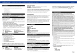
Front Panel LEDs
LED
Color
Status
Power
Green
ON = power on.
OFF = power off.
Alarm
Red
Alarm situation, Ex.: Link down
10/100M-TX, 100Base-FX/BX/SFP
Link
Active
Green
ON = Valid network connection is
established.
Flashing = Port sending or
receiving data.
1000M-T/SX/LX/SFP
Link
Active
Green
ON = Valid network connection is
established.
Flashing = Port sending or
receiving data.
Console Configuration
Connect to the switch console by connecting the DB-9 cable to the console port of
the switch and to the serial port of the computer running a terminal emulation
application (such as HyperTerminal or Putty).
Configuration settings of the terminal-emulation program: Baud rate:
115,200bps, Data bits: 8, Parity: none, Stop bit: 1, Flow control: none.
The default login name is “root,” no password.
Web Configuration
Connect to the switch using either one of the RJ45 ports on the front, or the
console port on the rear of the device.
Log in to the switch by launching a web browser and entering 192.168.1.10 in the
address bar. Enter the default login ID: root (no password) and click “Login.”

W70G-EX270V2Q3 Page 2
Copyright 2023 EtherWAN Systems, Inc. All Rights Reserved 03/06/2023
Installation Guide
EX27000 Series | Hardened Managed Ethernet Switch
Other Electrical and Safety Information
(A) Elevated Operating Ambient - If installed in a closed or multi-unit rack
assembly, the operating ambient temperature of the rack environment may be
greater than room ambient. Therefore, consideration should be given to installing
the equipment in an environment compatible with the maximum ambient
temperature (Tma).
B) Mechanical Loading - Mounting of the equipment in the rack should be such
that a hazardous condition is not achieved due to uneven mechanical loading.
C) Circuit Overloading - Consideration should be given to the connection of the
equipment to the supply circuit and the effect that overloading of the circuits
might have on overcurrent protection and supply wiring. Appropriate
consideration of equipment nameplate ratings should be used when addressing
this concern.
D) Reliable Earthing - Reliable earthing of rack-mounted equipment should be
maintained. Particular attention should be given to supply connections other than
direct connections to the branch circuit (e.g. use of power strips).
Do not disable the power cord grounding plug. The grounding plug is an
important safety feature.
Caution:
This equipment shall be used with all power supplies connected simultaneously.
This equipment is intended to be used in a restricted access location and by
qualified personnel. This equipment is not suitable for use in locations where
children are likely to be present.
Les matériels sont destinés à être installés dans des EMPLACEMENTS À ACCÈS
RESTREINT.
This equipment must be connected to Protective earthing (PE) to AC mains
ground. The protective earthing conductor shall be minimum 18 AWG and having
green-and-yellow insulation. The thread diameter of screw type terminal shall be
minimum 3.5mm.
The ground wire should be installed first (earlier than live and neutral ires) and
then removed. The grounding wire should be longer than live and neutral wires.
When wiring the switch to power, unscrew the two retaining screws that hold the
protective cover in place. The metal protective cover should be reattached after
the wiring is completed to avoid the danger of electric shock.
When stripping the cable sheath for connection to the terminal block, leave only
10mm of wires exposed for the connection.
The power cord shall be IEC 60227 certified, rated 0.75 mm2 x 3C or UL
recognized minimum 18AWG.
Terminal Block:
This product is intended to be supplied by certified DC power source and rated
output rating: 48 VDC, 0.8 A minimum.
AC Terminal Block
AC power rating current is 0.8A. All power connection wiring by a qualified
electrician in accordance with National Electrical Code, ANSI/NFPA 70 and
Canadian Electrical Code, Part I, CSA C22.1. An IEC certified or UL listed single-
phase type circuit-breaker, rated maximum 20A, shall be installed between mains
circuit and equipment.
Thumbscrews should be tightened with a tool after both initial installation
subsequent access to the panel.
Note:
This equipment must use UL recognized Laser Class 1 optical transceiver.
Manufacturer information:
EtherWAN Systems, Inc.
33F, No. 93, Sec. 1, Xintai 5th Rd., Xizhi Dist., New Taipei City, 221 Taiwan
The full product manual can be downloaded from:
www.etherwan.com
Hazardous voltages may occur within this unit when connected to
all power supplies. Prevent access to hazardous voltages by disconnecting
this equipment from all power supplies.
Plug the power cord into a grounded (earthed) electrical outlet that
is easily accessible at all times.
/