EtherWAN EG97023 Series Quick Installation Guide
- Catégorie
- Commutateurs réseau
- Taper
- Quick Installation Guide

Page 1
Installation Guide |
EG97023 Series Layer 3 Hardened Managed Ethernet Switch
08/30/2022
Copyright 2022 EtherWAN Systems, Inc. All Rights Reserved
Unpacking
Open the carton and unpack the items. Your package should include:
▪ EG97023 Ethernet switch with RJ-45/SFP/USB dust covers installed
▪ 2 Mounting brackets
▪ 12 Mounting screws
▪ 1 RJ-45 Console cable
▪ 1 AC Power Cord (optional)
▪ Quick install guide
What Else You Need
▪ Shielded twisted pair cables and corresponding shielded RJ45 connectors
▪ Appropriate SFP cable and SFP modules for SFP ports
Select a Location
Equipment is intended for
installation in Restricted
Access Location
Les matériels sont destinés à être installés
dans des EMPLACEMENTS À ACCÈS
RESTREINT
▪ Installation: Rack mount. Use the enclosed brackets and screws to mount the
switch in an open or enclosed 19” rack.
▪ Select a power source within 6 feet (1.8 meters).
▪ Choose a dry area with ambient temperature between -40 and 75°C (Models
EG97023-2VX (X = WR, CR, WR-CC or CR-CC), (CR and CR-CC use in US/CSA
only)); -40 and 65 °C for (Models EG97023-2VX (X = CR or CR-CC)).
▪ Keep away from heat sources, sunlight, warm air exhausts, hot-air vents, and
heaters.
▪ Be sure there is adequate airflow.
Caution
Shock hazard
Disconnect all power
sources
Mise en garde
Risque d'électrocution
Débranchez toutes les sources
d'alimentation
Connect to the Data Ports
The EG97023 has the following ports:
▪ 8 x 100/1000 BASE dual rate SFP ports
▪ 12 x 1/10G dual rate SFP+ ports
▪ 1 x RJ-45 management port with dust cover
▪ 1 x RJ-45 console port with dust cover
▪ 1 x USB console port
▪ 1 x USB backup/load configuration port
Use category 5e or higher UTP/STP cable for TX ports. For SFP and SFP+ ports,
ensure that the same type of transceiver is used at both ends of the link and that
the correct type of fiber cable is used.
Connect Power
Caution
Shock hazard
Connect to earth before
connecting to supply
Mise en garde
Risque d'électrocution
Connectez à la terre avant de
connecter à l'alimentation
Power Input Interfaces
VWR, VWR-CC – 100-240VAC / 100-250VDC Redundant (Terminal Block)
VCR, VCR-CC – 100-240VAC Redundant (AC Inlet)
If your EG97023 comes with AC power cables, connect the cables into the power
modules at the back of the switch. If your switch comes with an AC terminal block
(no cable), then connect the switch to a suitable power supply using 10 to 18
AWG wire. Redundant power supply is supported. However, only one power
input is required to operate the switch. Input voltage is 100 – 240 VAC.
Relay Output Alarm
The switch provides one dry contact for signaling of a user-defined power or port
failure. The alarm relay default is “open” and forms a closed circuit when the
event occurs. The relay output can be connected to an alarm signaling device.
Relay output current is 30VDC / 0.6A.
NOTE: The initial normal state of the relay is open, and if switch loses *all* power,
then this state will come into effect. This is important to remember when using
the relay to indicate a power failure. The relay will close in an alarm state when
there is redundant power input and an alarmed input fails.
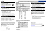
Front Panel LEDs
LED Panel Layout
Power 1 & 2
Green Power on, Off No power
Link/Act
Green: Network connection established
Flashing: Port sending or receiving data
Red: Link down or power down
Reset Button: Press and hold for less than 10 seconds to reboot the switch. Press
and hold for more than 10 seconds to reset the switch to the default password.
Console Configuration
Connect to the switch using the enclosed Ethernet cable to connect a serial port
on a PC to the RJ-45 Management port located on the front panel next to the USB
port. The IP address of VLAN 1 is 192.168.1.10.
Configuration via CLI
If using a terminal-emulation program such as Putty, configuration settings are:
Baud rate: 115,200bps, Data bits: 8, Parity: none, Stop bit: 1, Flow control: none.
The default login name is “root,” no password.
Web Configuration
Log in to the switch by launching a web browser and entering 192.168.1.10 (or
192.168.2.10 via the RJ-45 management port) in the address bar. Enter the
default login ID: root (no password) and click “Login.”
USB Port
The switch is equipped with one USB port (Type A connector) for configuration
file and syslog backup. The USB port can be used to save the configuration and
Syslog to a (FAT32) USB storage device.
Plug the device into the USB port, and use the “Save Configuration” command in
the web interface, or “copy running-config startupconfig” in the CLI. Use the
“Export Logs to USB” command in the web interface, or “export logs” in the CLI.
Other Information
The power cord must be connected to a properly earth grounded outlet.
Rack Mount Instructions - The following or similar rack-mount instructions are
included with the installation instructions:
A
Elevated Operating Ambient - If installed in a closed or multi-unit rack
assembly, the operating ambient temperature of the rack environment
may be greater than room ambient. Therefore, consideration should be
given to installing the equipment in an environment compatible with the
maximum ambient temperature (Tma) specified by the manufacturer.
B
Reduced Air Flow - Installation of the equipment in a rack should be such
that the amount of air flow required for safe operation of the equipment
is not compromised.
C
Mechanical Loading - Mounting of the equipment in the rack should be
such that a hazardous condition is not achieved due to uneven
mechanical loading.
D
Circuit Overloading - Consideration should be given to the connection of
the equipment to the supply circuit and the effect that overloading of the
circuits might have on overcurrent protection and supply wiring.
Appropriate consideration of equipment nameplate ratings should be
used when addressing this concern.
E
Reliable Earthing - Reliable earthing of rack-mounted equipment should
be maintained. Particular attention should be given to supply connections
other than direct connections to the branch circuit (e.g. use of power
strips).
The socket-outlet shall be installed near the equipment and shall be easily
accessible.
▪ Do not disable the power cord grounding plug. The grounding plug is an
important safety feature
▪ Plug the power cord into a grounded (earthed) electrical outlet that is easily
accessible at all times.
▪ The means of power cord of adapter should be connected to a socket-outlet
with earthing connection.
▪ This equipment is intended to be used in a restricted access location and be
used by a qualified person.
▪ This equipment is not suitable for use in locations where children are likely to
be present.
▪ The power cord shall be IEC 60227 certified, rated 0.75 mm2 x 3C or UL
recognized minimum 18AWG
AC Inlet

Page 2
Installation Guide
Copyright 2022 EtherWAN Systems, Inc. All Rights Reserved
EG97023 Layer 3 Hardened Managed Ethernet Switch | W70G-EG97023Q1
All power connection wiring should be made by a qualified electrician in
accordance with National Electrical Code, ANSI/NFPA 70 and Canadian Electrical
Code, Part I, CSA C22.1. An IEC certified or UL listed single-phase type circuit-
breaker, rated maximum 20A, shall be installed between mains circuit and
equipment.
Thumbscrews should be tightened with a tool after both initial installation
subsequent access to the panel.
Note: This equipment must use UL recognized Laser Class 1 optical transceiver.
This equipment is intended to be used in a restricted access location and be used
by a qualified person.
This equipment is not suitable for use in locations where children are likely to be
present.
Caution
This product relies on the building's installation for short-circuit (overcurrent)
protection and power disconnection. Ensure that the protective device is rated
MAX 20 A, 250 V and shall be easily accessible.
The performance levels of the field wiring terminals provided for power supply
connection:
a. Range of wire sizes: 10 - 18 AWG
b. Conductor material: copper wire only
c. Tightening torque(s): 14 In.-Lb
Manufacturer information:
ETHERWAN SYSTEMS, INC.
33F, No. 93, Sec. 1, Xintai 5th Rd., Xizhi Dist., New Taipei City, 221 Taiwan
www.etherwan.com
If any items are missing or damaged, notify your EtherWAN representative.
If possible, save the carton and packing material in case you need to ship or
store the switch in the future. The full product manual can be downloaded
from:
www.etherwan.com
-
 1
1
-
 2
2


EtherWAN EG97023 Series Quick Installation Guide
- Catégorie
- Commutateurs réseau
- Taper
- Quick Installation Guide
dans d''autres langues
- English: EtherWAN EG97023 Series
Documents connexes


Autres documents
-
red lion NT328G Hardware Manuel utilisateur
-
-
-
-
Westermo L206-F2G-EX Mode d'emploi
-
Foundry Networks FES12GCF Guide d'installation
-
Westermo L208-F2G-S2-EX Mode d'emploi
-
Westermo L106-F2G EX Mode d'emploi