Philips MX5100VR Manuel utilisateur
- Catégorie
- Lecteurs DVD
- Taper
- Manuel utilisateur

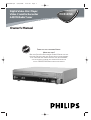
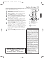
MX5100VR
Digital Video Disc Player
Video Cassette Recorder
THANK YOU FOR CHOOSING PHILIPS.
N
EED HELP FAST?
READ YOUR QUICK-USE GUIDE AND/OR OWNER’S MANUAL FIRST FOR
QUICK TIPS THAT MAKE USING YOUR
PHILIPS PRODUCT MORE ENJOYABLE.
I
FYOU HAVE READYOUR INSTRUCTIONS AND STILL NEED ASSISTANCE,
YOUMAY ACCESS OUR ONLINE HELP AT WWW.P4C.PHILIPS.COM
OR CALL
1-800-531-0039 WHILE WITH YOUR PRODUCT.
Owner’s Manual
MX5100VR.qxd 6/04/2004 3:37 PM Page 1
AM/FM Radio Tuner

Registering your model with PHILIPS makes you eligible for all of the valuable benefits listed below,so
don't miss out.Complete and return your Product Registration Card at once to ensure:
Return your Product Registration Card today
to get the very most from your purchase.
For Customer Use
Enter below the Serial No.which is
located on the rear of the cabinet.
Retain this information for future
reference.
Model No. ____________________
Serial No. ____________________
Know these
safetysymbols
This “bolt of lightning” indicates
uninsulated material within your unit
may cause an electrical shock.For the safe-
ty of everyone in your household,please
do not remove product covering.
The “exclamation point” calls atten-
tion to features for which you
should read the enclosed literature closely
to prevent operating and maintenance
problems.
WARNING:To r educe the risk of fire or
electric shock,this apparatus should not be
exposed to rain or moisture,and objects
filled with liquids,such as vases,should not
be placed on this apparatus.
CAUTION:To prevent electric shock,
match wide blade of plug to wide slot,fully
insert.
ATTENTION:Pour éviter les choc élec-
triques,introduire la lame la plus large de
la fiche dans la borne correspondante de la
prise et pousser jusqu’au fond.
*Proof of
Purchase
Returning the enclosed card guaran-
tees that your date of purchase will
be on file, so no additional paper-
work will be required from you to
obtain warranty service.
*Product Safety
Notification
By registering your product,you'll
receive notification - directly from
the manufacturer - in the rare case
of a product recall or safety defect.
*Additional Benefits
of Product
Ownership
Registering your product guarantees
that you'll receive all of the privileges
to which you're entitled,including
special money-saving offers.
Visit our World Wide Web Site at http://www.philips.com
t
s
Congratulations on your purchase,
and welcome to the “family!”
Dear PHILIPS product owner:
Thank you for your confidence in PHILIPS.You’ve select-
ed one of the best-built,best-backed products available
today.We’ll do everything in our power to keep you
happy with your purchase for many years to come.
As a member of the PHILIPS “family,” you’re entitled to
protection by one of the most comprehensive warranties
and outstanding service networks in the industry.What’s
more,your purchase guarantees you’ll receive all the
information and special offers for which you qualify, plus
easy access to accessories from our convenient home
shopping network.
Most importantly,you can count on our uncompromising
commitment to your total satisfaction.
All of this is our way of saying welcome - and thanks for
investing in a PHILIPS product.
P.S. To get the most from your PHILIPS pur-
chase, be sure to complete and return your
Product Registration Card at once.
MX5100VR.qxd 6/04/2004 3:37 PM Page 2

Safety Precautions
Warning: To prevent fire or shock hazard, do not expose this equipment to rain or moisture.
Federal Communications Commission (FCC) Warning: Any unauthorized changes or
modifications to this equipment void the user’s authority to operate it.
Laser Safety:This unit employs a laser. Only a qualified service person should remove the cover or
attempt to service this device, due to possible eye injury.
CAUTION: USE OF CONTROLS OR ADJUSTMENTS OR PERFORMANCE OF PROCEDURES OTHER
THAN THOSE SPECIFIED HEREIN MAY RESULT IN HAZARDOUS RADIATION EXPOSURE.
CAUTION: VISIBLE AND INVISIBLE LASER RADIATION WHEN OPEN AND INTERLOCK DEFEATED.
DO NOT STARE INTO BEAM. THE BEAM IS LOCATED INSIDE, NEAR THE DECK MECHANISM.
Special Information for Canadian Users:This Class B digital apparatus complies with Canadian
ICES-003. Cet appareil numérique de la classe B est conforme à la norme NMB-003 du Canada.
Radio/TV Interference:This equipment has been tested and found to comply with the limits for a
Class B digital device, pursuant to Part 15 of the FCC Rules. These limits are designed to provide reasonable
protection against harmful interference in a residential installation. This equipment generates, uses, and can
radiate radio frequency energy and, if not installed and used in accordance with the instructions, may cause
harmful interference to radio communications. However, there is no guarantee that interference will not
occur in a particular installation. If this equipment does cause harmful interference to radio or television
reception, which can be determined by turning the equipment off and on, the user is encouraged to try to
correct the interference by one or more of the following measures:
1) Reorient or relocate the receiving antenna.
2) Increase the separation between the equipment and the receiver.
3) Connect the equipment into an outlet on a circuit different from that to which the receiver is connected.
4) Consult the dealer or an experienced radio/TV technician for help.
Copyright Protection:Unauthorized copying, broadcasting, public performance and lending of Discs
are prohibited. This product incorporates copyright protection technology that is protected by method claims
of certain U.S. patents and other intellectual property rights owned by Macrovision Corporation and other
rights owners. Use of this copyright protection technology must be authorized by Macrovision Corporation
and is intended for home and other limited viewing uses only unless otherwise authorized by Macrovision
Corporation. Reverse engineering or disassembly is prohibited.
Note to the Cable TV System Installer: This reminder calls the Cable TV system installer’s
attention to Article 820-40 of the National Electrical Code, which provides guidelines for proper grounding –
in particular, specifying that the cable ground shall be connected to the grounding system of the building, as
close to the point of cable entry as possible.
Declaration of Conformity
Model Number: MX5100VR
Trade Name: Philips
Responsible Party: Philips Consumer Electronics
P.O. Box 14810
Knoxville, TN 379
14-1810
(865) 52
1-4316
Safety and General Information 3
Manufactured under license from Dolby Laboratories. "Dolby," “Pro Logic,” and
the double-D symbol are trademarks of Dolby Laboratories.
Copyright 2004 Philips. All rights reserved.
MX5100VR.qxd 6/04/2004 3:37 PM Page 3

4 Table of Contents
General Information
Safety and General Information . . . . . . . . . . . . . . .3
Table of Contents . . . . . . . . . . . . . . . . . . . . . . . . .4
Introduction . . . . . . . . . . . . . . . . . . . . . . . . . . . . .5
Playable Discs and Video Cassettes . . . . . . . . . . . .6
Initial Setup
Hookups . . . . . . . . . . . . . . . . . . . . . . . . . . . . .7-15
Antenna Connections . . . . . . . . . . . . . . . . . . . . .16
Speaker Setup . . . . . . . . . . . . . . . . . . . . . . . . .17-18
Remote Control Setup . . . . . . . . . . . . . . . . . . . .18
First-time Setup . . . . . . . . . . . . . . . . . . . . . . . . . .19
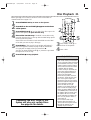
Basic Playback
Video Cassette Playback . . . . . . . . . . . . . . . . . . .20
Disc Playback . . . . . . . . . . . . . . . . . . . . . . . . . . . .21
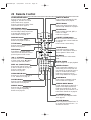
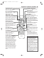
Basic Controls
Remote Control . . . . . . . . . . . . . . . . . . . . . .22-23
Front Panel . . . . . . . . . . . . . . . . . . . . . . . . . . .24-25
Display Panel . . . . . . . . . . . . . . . . . . . . . . . . . . . .26
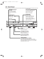
Rear Panel . . . . . . . . . . . . . . . . . . . . . . . . . . . . . .27
Additional VCR Setup
Channel Setup . . . . . . . . . . . . . . . . . . . . . . . .28-29
Clock (VCR) . . . . . . . . . . . . . . . . . . . . . . . . . .30-31
Language (VCR) . . . . . . . . . . . . . . . . . . . . . . . . . .32
VCR Status Displays . . . . . . . . . . . . . . . . . . . . . .33
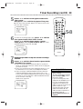
Videotape Recording Options
Videotape Recording . . . . . . . . . . . . . . . . . . . . . .34
Recording One Channel/Watching Another . . . . .35
One-Touch Recording . . . . . . . . . . . . . . . . . . . . .36
Rerecording (Tape Duplication) . . . . . . . . . . . . . .37
Timer Recording . . . . . . . . . . . . . . . . . . . . . .38-40
DVD to Videotape Duplication . . . . . . . . . . . . . .41
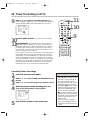
Videotape Playing Options
Repeat Play . . . . . . . . . . . . . . . . . . . . . . . . . . . . .42
Tape Counter . . . . . . . . . . . . . . . . . . . . . . . . . . .43
Time Search,Index Search . . . . . . . . . . . . . . . . . .44
Special Effects Playback . . . . . . . . . . . . . . . . . . . .45
Automatic Operation Features . . . . . . . . . . . . . .46
Additional VCR Features
Multi-Channel Television Sound . . . . . . . . . . . . . .47
Hi-Fi Stereo . . . . . . . . . . . . . . . . . . . . . . . . . . . . .48
Speaker and Sound Settings
Digital Sound,Surround Sound . . . . . . . . . . . . . .49
DelayTime . . . . . . . . . . . . . . . . . . . . . . . . . . .50-51
Speaker Balance . . . . . . . . . . . . . . . . . . . . . . .52-53
Disc Playback Features
DVD Disc Menus . . . . . . . . . . . . . . . . . . . . . . . . .54
Fast Forward/Reverse Search . . . . . . . . . . . . . . . .55
Title/Chapter Playback,Time Playback . . . . . . . . .56
Track Playback . . . . . . . . . . . . . . . . . . . . . . . . . . .57
Paused and Step-by-Step Playback, Resume . . . . .58
Repeat,A-B Repeat . . . . . . . . . . . . . . . . . . . . . . .59
Markers . . . . . . . . . . . . . . . . . . . . . . . . . . . . . . .60
Subtitles,Camera Angles . . . . . . . . . . . . . . . . . . .61
Slow Motion,Zoom . . . . . . . . . . . . . . . . . . . . . . .62
Programs,Random Play . . . . . . . . . . . . . . . . . . . .63
Parental Controls Password . . . . . . . . . . . . . . . .64
Parental Levels . . . . . . . . . . . . . . . . . . . . . . . . . . .65
Audio Language, Stereo Sound . . . . . . . . . . . . . . .66
MP3/JPEG/Picture CD Playback . . . . . . . . . . . . . .67
MP3/JPEG/Picture CD Displays . . . . . . . . . . . . . .68
DVD Player Setup Options
Display . . . . . . . . . . . . . . . . . . . . . . . . . . . . . . . . .69
Language . . . . . . . . . . . . . . . . . . . . . . . . . . . . .70-71
Audio . . . . . . . . . . . . . . . . . . . . . . . . . . . . . . . . .72
On-Screen Displays . . . . . . . . . . . . . . . . . . . . . . .73
Black Level . . . . . . . . . . . . . . . . . . . . . . . . . . . . . .74
AM/FM Radio
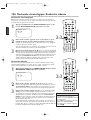
Selecting Radio Stations . . . . . . . . . . . . . . . . . . . .75
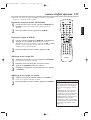
Preset Radio Stations . . . . . . . . . . . . . . . . . . . . . .76
Information You May Need
Glossary, Specifications . . . . . . . . . . . . . . . . . . . .77
Helpful Hints . . . . . . . . . . . . . . . . . . . . . . . . .78-81
Limited Warranty . . . . . . . . . . . . . . . . . . . . . . . . .82
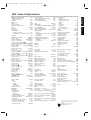
Information Index . . . . . . . . . . . . . . . . . . . . . . . .83
MX5100VR.qxd 6/04/2004 3:37 PM Page 4

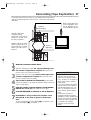
Introduction 5
VCR Features
• Automatic Head Cleaner
• Channel Setup
• English, French,and Spanish menus and displays
• Multi-Channel TV Sound
• 19 Micron head
• Recording:One-Touch and Timer
• Repeat Play
• Searching:Time, Index,Forward,and Reverse
• Slow Motion
• Still Picture
•Tape Counter
•Tracking Adjustment
Welcome!
This System combines a Digital Video Disc (DVD) Player,a Hi-Fi Video Cassette Recorder (VCR),and an AM/FM
Radio Tuner into one unit,letting you play DVDs,Audio Compact Discs (Audio CDs),and Video Cassettes on
one piece of equipment.
This DVD Digital Home Cinema System creates the same dynamic sound qualities that you find in cinemas and
incorporates some of the best features in home theater technology.
Read this owner’s manual carefully to learn how to use the features listed below.
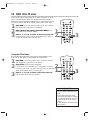
DVD Disc Menus...
Some explanations in this manual describe DVD Disc menus.DVD manufacturers set the menus,which vary
among DVDs.All DVDs do not have menus.If the DVD has a menu,access it by pressing DVD, then
DISC/MENU on the remote control.Details are on page 54.
DVD Player Setup Menu...
Some instructions explain how to use the DVD Player’s Setup menu to set up features of the DVD Player or a
DVD. Access the DVD Player menu by pressing DVD,then SETUP/PROG on the remote control when playback is
stopped.Even if a feature is set in the DVD Player’s menu,it may not be available if the current DVD does not
include that feature.
Available Disc Features...
All features described in this manual are not available on every Disc.If the feature is not
available on the Disc,you cannot use the System to make it available.An “X” will appear in the
top right corner of the TV screen if you try to access a feature that is not currently available.
Disc Features
• Audio Language choices*
• Bit Rate display
• Camera Angle *
• Dolby Digital Sound*
•DVD to Videotape Duplication
• Dynamic Range Control
• Fast/Paused/Slow/Step-by-Step Playback
• Markers
• Parental Controls*
•Program Playback
• Random Playback
• Repeat, Repeat A-B
• Screen Saver
• Search (Title/Chapter,Time,Track)
• Subtitles*
• Zoom
*
If available on the DVD
AM/FM Radio Tuner Features
• FM/AM radio • Preset programming of up to 40 radio stations
Package Contents
The following items are provided with your new System.
• Remote Control and two AA batteries
• One black RF coaxial cable,75 ohm
• AM Loop Antenna
•FM Wire Antenna
• One set of Audio (red and white tips) and
Composite Video (yellow tips) cables
• Speaker and Subwoofer Cables
• Brackets and Screws
• This Owner’s Manual and Quick-Use Guide
MX5100VR.qxd 6/04/2004 3:37 PM Page 5

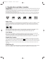
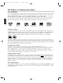
6 Playable Discs and Video Cassettes
Region Codes
This System has a Region One (1) DVD Player.DVDs must be labeled for ALL regions or for Region 1 in order
to play on the DVDPlayer.You cannot play DVDs that are labeled for other regions.Look for the symbols
below on your DVDs.If these region symbols do not appear on your DVD,you cannot play the DVD in this
DVD Player.
The number inside the globe refers to a region of the world.Region 1 represents the United States,Canada,
upper regions of North America,Bermuda,the U.S.Virgin Islands,and small regions near Australia.
A DVD labelled for a specific region can only play on DVD Players with the same region code.
Color Systems
DVDs are recorded in different color systems throughout the world.The most common color systems are
NTSC (which is used primarily in the United States and North America),PAL,and SECAM.
This DVD Player uses NTSC,so DVDs you play must be recorded in the NTSC system.You cannot play DVDs
recorded in other formats.The color system of the DVD may be listed on the DVD or on the Disc case.
Playable Video Cassettes
The VCR of this System has a High Quality (HQ) system and is compatible with existing Video Home System
(VHS) equipment.Use only video cassettes that have the mark.The use of other tapes may result in poor
picture quality and excessive deposits on the video heads, which may not be covered by the warranty if damage
occurs.
The VCR also has a 19 micron head,which provides a better picture when you view tapes recorded in slow
speed (SLP).
Kodak Picture CD
This product complies with the KODAK Picture CD format and will display KODAK Picture CDs.The “KODAK
Picture CD Compatible” logo is a trademark of Eastman Kodak Company and is used with permission.
Recordable
ReWritable
Playable Discs
The DVD Player will play Digital Video Discs (DVDs);Audio Compact Discs (CDs); Video CDs;finalized Digital
Video Discs Rewritable (DVD+RW);and finalized Compact Discs Rewritable (CD-RW) and Compact Discs
Recordable (CD-R),including Picture CDs.
To play a DVD,make sure it meets the requirements for Region Codes and Color Systems as described below.
Discs that have the following logos will play on the DVD Player.Other Disc types are not guaranteed to play.
DVD Video CD Audio CD CD-RW/CD-R DVD+RW Picture CD
DIGITAL VIDEO
MX5100VR.qxd 6/04/2004 3:37 PM Page 6

Hookups 7
Determining the best possible connection...
Your hookup will be determined by your existing equipment,especially your TV.These guidelines describe which
options have the best picture (video) and sound (audio) quality.You will not use all the jacks on the System.
If your TV only has an RF-style jack,usually labelled Antenna In, RF In, or 75 ohm, use the
System’s TV ANTENNA OUT jack to connect to the TV. This hookup provides both audio and
video in a single cable. Set your TV to channel 3 or 4 - the output channel of the System.This
connection allows you to use both the DVD and VCR features.
Details are on page eight.
If your TV has Component Video In jacks (which could be labelled Y Cr Cb,Y Pr Pb,or YUV and may
be green,blue,and red),use the COMPONENT VIDEO OUT jacks (Y Pb/Cb Pr/Cr) for the best
picture quality.
If you use only this video connection,only the DVD picture will be available.To see DVD features on
the TV, set the TV to its Component Video In channel.
Details are on page 12.
If your TV has an S-Video In jack (which may be labelled Y/C or S-VHS),use the S-VIDEO OUT jack
for excellent picture quality.If you use only this video connection,only the DVD picture will be
available.To see DVD features on the TV,set the TV to its S-Video In channel.
Details are on page 13.
If your TV has a single yellow Video In jack (which may be labelled CVBS,Composite,or baseband),
use the yellow VIDEO (DVD/VCR OUT) jack for good picture quality.This connection provides a
picture for both the DVD Player and the VCR.Set the TV to its Video In channel.
Details are on page 11.
If you have a Stereo with a Coaxial Digital Audio In jack,this provides the clearest sound for the
DVD Player.Connect the System’s DIGITAL AUDIO OUT COAXIAL jack to your Stereo.If you use
only this audio connection,only Disc sound (no VCR) will be available.
Details are on page 15.
If digital audio connections are not possible,connect the System’s red and white AUDIO (DVD/VCR
OUT) jacks to the Audio In jacks of your Stereo or TV. This provides sound for both the DVD
Player and the VCR.
Details are on pages 11-14.
Before you begin...
● Refer to the manuals of your TV,Cable Box,Stereo,or other devices as necessary.Note the style of jacks
and connectors on the other equipment.Determine how to choose different Audio and Video In channels on
your other equipment so you can see and hear the System playing on the TV,Stereo,etc.
● Disconnect all equipment from the power outlets.Connect the equipment to the power outlets only after
you have finished hooking up everything.Never make or change connections with equipment connected to
the power outlet.
Remember...
● Set the TV to the correct Video In channel.Such channels may be called AUX or AUXILIARY IN,
AUDIO/VIDEO or A/V IN,EXT1 or External In,etc.These channels often are located near channel zero.See
your TV owner’s manual for details.If you do not see the DVD or VCR playback on the TV,go to the lowest
TV channel (01 or 02) and change channels downward until you see the DVD or VCR picture on the TV. Or,
if your TV has only a single Antenna In jack and you are using the RF coaxial cable (as described on page
eight),set the TV to channel 3 or 4.
To find the right Audio/Video In channel,turn on the System.Press DVD to put the System in DVD mode.
With no Disc in the Player,a large DVD logo will appear on the TV screen when you get the TV on the
correct Audio/Video In channel or channel 3 or 4.
● Set a separate Stereo (if applicable) to the correct channel or “source” mode.
● Depending on your connection,you may need to purchase additional cables or adaptors.
● To use the VCR features,you must include a connection with the supplied yellow video cable
and red/white audio cables or with the supplied RF coaxial cable.
Once you determine the best option,find your choice on pages 8-15. Follow the specific steps for
the hookup you choose.
MX5100VR.qxd 6/04/2004 3:37 PM Page 7

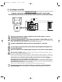
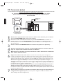
8 Hookups (cont’d)
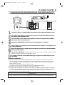
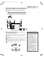
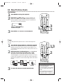
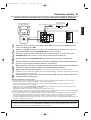
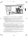
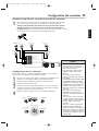
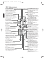
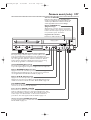
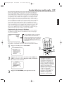
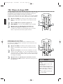
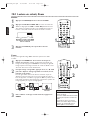
System to TV only
Simplest connection using only the supplied black RF coaxial cable
This connection will let you use the features of both the VCR and the DVD Player.
VIDEO
TV ANTENNA
AUDIO
R L
PROGRESSIVE
OUT
IN
ANTENNA 75Ω
ANTENNA 75Ω
Y
Pb/Cb
Pr/Cr
FM
(75Ω)
DIGITAL
AUDIO OUT
COAXIAL
S-VIDEO
OUT
VCR
IN
DVD/
VCR
OUT
COMPONENT
VIDEO OUT
AM
FL
FR
C
SL
SR
W
SPEAKER (4Ω)
P I
Antenna
or Cable TV
Signal
Back of TV
(example only)
ANTENNA IN
RF IN
RF coaxial cable
1
Disconnect the antenna or Cable TV signal from your TV and connect it to the TV
ANTENNA IN jack on the System.
2
Connect the supplied black RF coaxial cable to the System’s TV ANTENNA OUT jack
and to the Antenna In jack on the TV. The ANTENNA IN jack on the TV may be labelled TV IN,
RF IN,75Ω (ohm), or ANT.IN. See your TV owner’s manual for assistance.
3
Set the P/I PROGRESSIVE switch on the rear of the System to I (Interlace).
4
You are ready to connect the AM and FM antennas and the Speakers.See pages 16-17
to connect these items.
5
When all connections are complete, plug in the power cords of the TV and the System.
6
Set your TV to channel 3 or 4. The System’s output channel is 3 when you purchase it. So,set
your TV to channel 3 when the System is new.
If you cannot use channel 3 at your TV,you can change the System’s output channel to channel 4.To
do so,press the VCR button to put the System in VCR mode.The red VCR light will be on the front
of the System.Insert a videotape and press PLAY
B to start playback. (You cannot change the
System’s output channel when you adjust the tracking manually.In this case, press STOP
C to stop
the playback once.Then, press PLAY B to start playback again.)
During playback, press and hold the (VCR) PLAY B button on the front of the System
for three to five seconds.
Each time you do this,the System’s output channel switches between 3
and 4.Change your TV to channel 3 or 4 accordingly.
There is not a channel 3/4 switch on the System (as customary with most VCRs).
7
If you have not turned on the System already, go to page 19 to complete the VCR’s
First-Time Setup. This process sets up the TV channels and the language for the VCR menu.
MX5100VR.qxd 6/04/2004 3:37 PM Page 8

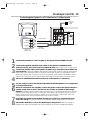
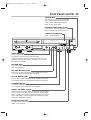
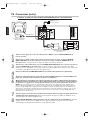
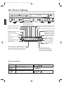
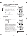
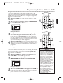
Hookups (cont’d) 9
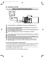
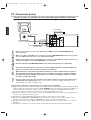
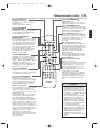
Connecting the Cable Bo
x/Satellite Receiver to the System and to a TV
This connection will let you use the features of both the VCR and the DVD Player.
• If your Cable Box/Satellite Receiver has Audio/Video Out jacks,use audio/video cables to connect them to the
AUDIO and VIDEO (VCR IN) jacks on the System.You will not need the RF coaxial cable as described at step 2.
Helpful Hint
1
Connect a Cable TV or Satellite signal to the IN jack on the Cable Box/Satellite Receiver.
2
Use an RF coaxial cable to connect the OUT Jack on the Cable Box/Satellite Receiver to
the System’s TV ANTENNA IN jack.
3
Use a second RF coaxial cable (one is supplied) to connect the System’s TV ANTENNA
OUT jack to the TV’s Antenna In jack.
4
Set the P/I PROGRESSIVE switch on the rear of the System to I (Interlace).
5
You are ready to connect the AM and FM antennas and the Speakers.Go to pages 16-17 to
connect these items.
6
When all connections are complete,plug in the power cords of the TV,Cable Box/Satellite
Receiver, and the System.
7
Set your TV to channel 3. If you cannot use channel 3 at your TV,you can change the System’s output
channel to channel 4.See step 6 on page eight for details.
8
If you have not turned on the System already,go to page 19 to complete the VCR’s First-
Time Setup.
With this connection ...
● Select TV channels at the Cable Box/Satellite Receiver,not the System.To record or view TV channels:
1) Press VCR to put the System in VCR mode.The red VCR light will appear on the front of the System.
2) Press SKIP i /CH o or SKIP j /CH p to set the System to the Cable Box/Satellite Receiver
output channel (03 or 04).
3) Set the TV to the System’s output channel (03 or 04).
4) Select the channel you want to view/record at the Cable Box/Satellite Receiver.
● You may not view a channel other than the one you are recording.
● Program a timer recording for one channel at a time. Set your Cable Box/Satellite Receiver to the channel
you want to record.When you enter the channel you want to record in a timer recording,select channel 03
or 04 (the Cable Box/Satellite Receiver output channel).(This is step 8 on page 39.) Leave the Cable
Box/Satellite Receiver on for a timer recording.
VIDEO
TV ANTENNA
AUDIO
R L
PROGRESSIVE
OUT
IN
ANTENNA 75Ω
ANTENNA 75Ω
Y
Pb/Cb
Pr/Cr
FM
(75Ω)
DIGITAL
AUDIO OUT
COAXIAL
S-VIDEO
OUT
VCR
IN
DVD/
VCR
OUT
COMPONENT
VIDEO OUT
AM
FL
FR
C
SL
SR
W
SPEAKER (4Ω)
P I
OUT IN
Back of TV
(example only)
ANTENNA IN
RF IN
RF coaxial cable
RF coaxial cable
Antenna or
Cable TV signal
MX5100VR.qxd 6/04/2004 3:37 PM Page 9

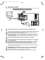
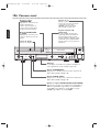
10 Hookups (cont’d)
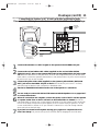
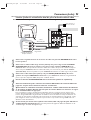
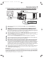
1
Connect the Cable TV or Satellite signal to the System’s TV ANTENNA IN jack.
2
Connect an RF coaxial cable to the System’s TV ANTENNA OUT jack and to the IN
jack on the Cable Box/Satellite Receiver.
3
Connect another RF coaxial cable to the OUT jack on the Cable Box/Satellite Receiver
and to the ANTENNA IN jack on the TV.
4
Set the P/I PROGRESSIVE switch on the rear of the System to I (Interlace).
5
You are ready to connect the AM and FM antennas and the Speakers.Go to pages 16-17
to connect these items.
6
When all connections are complete, plug in the power cords of all equipment. Set the
Cable Box/Satellite Receiver to channel 3 (the System’s default output channel). Set the
TV to the Cable Box/Satellite Receiver’s output channel (03 or 04).
7
If you have not turned on the System already, go to page 19 to complete the VCR’s
First-Time Setup. This process sets up the TV channels and the language for the VCR menu.
To watch one channel while recording another ...
1) Put the Cable Box/Satellite Receiver on channel 3 (the System’s default output channel). (To change it to
4,press and hold (VCR) PLAY
B on the front of the System for 3-5 seconds during tape playback. Details
are on page eight.) Set the TV to the Cable Box/Satellite Receiver output channel (03 or 04).
2) Press VCR to put the System in VCR mode.The red VCR light will appear on the front of the System.
3) Press VCR/TV on the remote to choose VCR position.
4) Press SKIP i /CH o or SKIP j /CH p to select the channel you want to record at the System.
Press REC
I or RECORD I to start the recording.
5) Press VCR/TV on the remote once to put the System in TV position.
6) Select the channel you want to watch at the Cable Box/Satellite Receiver.
System to Cable Bo
x/Satellite Receiver and TV
This connection will let you use the features of both the VCR and the DVD Player.
VIDEO
TV ANTENNA
AUDIO
R L
PROGRESSIVE
OUT
IN
ANTENNA 75Ω
ANTENNA 75Ω
Y
Pb/Cb
Pr/Cr
FM
(75Ω)
DIGITAL
AUDIO OUT
COAXIAL
S-VIDEO
OUT
VCR
IN
DVD/
VCR
OUT
COMPONENT
VIDEO OUT
AM
S
P
P I
OUT IN
Back of TV
(example only)
ANTENNA IN
RF IN
Cable Box/Satellite Receiver
(example only)
RF coaxial cable
RF coaxial cable
Cable TV
or Satellite Signal
MX5100VR.qxd 6/04/2004 3:37 PM Page 10

Hookups (cont’d) 11
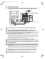
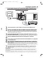
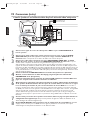
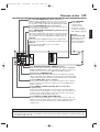
1
Connect the antenna or Cable TV signal to the System’s TV ANTENNA IN jack.
2
Connect the red and white audio cables (supplied) to the red and white AUDIO
(DVD/VCR OUT) jacks on the System and to the red and white AUDIO IN jacks on the
TV. Match the cable colors to the jack colors. If the TV has a single AUDIO IN jack,use the white
audio cable to connect the System’s white AUDIO L (left) (DVD/VCR OUT) jack to the TV’s AUDIO
IN jack.You will not use the red cable.
3
Connect the yellow video cable (supplied) to the System’s yellow VIDEO (DVD/VCR
OUT) jack and to the VIDEO IN jack on the TV. The VIDEO IN jack on the TV is usually
yellow and may be labelled CVBS, Composite, or Baseband video.
4
Set the P/I PROGRESSIVE switch on the rear of the System to I (Interlace).
5
You are ready to connect the AM and FM antennas and the Speakers.Go to pages 16-17
to connect these items.
6
When all connections are complete, connect the power cords of the TV and the System
to a power outlet.Turn on the TV and set it to the Audio/Video In channel.To find the
right Audio/Video In channel,turn on the System. Press DVD to put the System in DVD mode.With
no Disc in the Player,a large DVD logo will appear on the TV screen when you get the TV on the
correct Audio/Video In channel.Go to your lowest TV channel (01 or 02),then change channels
down until you see the DVD logo.
7
If you have not turned on the System already, go to page 19 to complete the VCR’s
First-Time Setup. This process sets up the TV channels and the language for the VCR menu.
Connecting the System to a TV that has
Audio and Video In jacks
This connection will let you use the features of both the VCR and the DVD Player.
VIDEO
TV ANTENNA
AUDIO
R L
PROGRESSIVE
OUT
IN
ANTENNA 75Ω
ANTENNA 75Ω
Y
Pb/Cb
Pr/Cr
FM
(75Ω)
DIGITAL
AUDIO OUT
COAXIAL
S-VIDEO
OUT
VCR
IN
DVD/
VCR
OUT
COMPONENT
VIDEO OUT
AM
P I
Antenna
or Cable TV
Signal
LEFT AUDIO IN
RIGHT AUDIO IN
VIDEO IN
LEFT AUDIO IN
RIGHT AUDIO IN
VIDEO IN
Back of TV
(example only)
yellow
video
cable
red/white
audio
cables
MX5100VR.qxd 6/04/2004 3:37 PM Page 11

12 Hookups (cont’d)
Connecting the System to a TV that has Component
Video In jacks
VIDEO
TV ANTENNA
AUDIO
R L
PROGRESSIVE
OUT
IN
ANTENNA 75Ω
ANTENNA 75Ω
Y
Pb/Cb
Pr/Cr
FM
(75Ω)
DIGITAL
AUDIO OUT
COAXIAL
S-VIDEO
OUT
VCR
IN
DVD/
VCR
OUT
COMPONENT
VIDEO OUT
AM
P I
Antenna
or Cable TV
Signal
LEFT AUDIO IN
RIGHT AUDIO IN
Cr/R-Y
Y
Cb/B-Y
LEFT AUDIO IN
RIGHT AUDIO IN
Y
Pb/Cb
Pr/Cr
Back of TV
(example only)
Component
Video
Cables
red/white
Audio
Cables
1
Connect the antenna or Cable TV signal to the System’s TV ANTENNA IN jack.
2
Connect the supplied red/white audio cables to the System’s red/white AUDIO
(DVD/VCR OUT) jacks and to the TV’s AUDIO IN jacks. Match cable colors to jack colors.
3
Connect component video cable to the System’s COMPONENT VIDEO OUT (Y Pb/Cb
Pr/Cr) jacks and to the COMPONENT VIDEO IN jacks on the TV. Component Video In
jacks on the TV are usually red, blue, and green.
The Component Video connection only supplies video (picture) for the DVD Player of the System.To use the
VCR or see TV channels,you must connect the RF coaxial cable or the yellow video cable.To connect the RF
coaxial cable,see step 2 on page eight.To connect the yellow video cable, see step 3 on page 11.If you are
using the RF coaxial cable for VCR playback, choose channel 3 or 4 at the TV.If you are using the yellow
video cable for VCR playback, choose the Video In channel at your TV.
4
Set the P/I PROGRESSIVE switch on the rear of the System to I (Interlace).
Or, if your TV has Progressive Scan,set the P/I PROGRESSIVE switch to P (Progressive).
5
You are ready to connect the AM and FM antennas and the Speakers.Go to pages 16-17
to connect these items.
6
When all connections are complete, connect the power cords of the System and TV to
a power outlet.Turn on the TV and set it to the Component Video In channel for DVD
Player features. To help you find the Component Video In channel, turn on the System.Press DVD
to put the System in DVD mode.With no Disc in the Player, a large DVD logo will appear on the TV
screen when you get the TV on the correct Component Video In channel. Go to your lowest TV
channel (01 or 02) and change channels down until you see the DVD logo on the TV screen.
7
If you have not turned on the System already, go to page 19 to complete the VCR’s
First-Time Setup. This process sets up the TV channels and the language for the VCR menu.
8
Set DOLBY DIGITAL to OFF in the DVD Player’s Setup menu. Details are on page 72.
Playing a DVD when the settings are wrong could distort the sound or damage the speakers.
MX5100VR.qxd 6/04/2004 3:37 PM Page 12

Hookups (cont’d) 13
Connecting the System to a TV that has an S-Video In jack
VIDEO
TV ANTENNA
AUDIO
R L
PROGRESSIVE
OUT
IN
ANTENNA 75Ω
ANTENNA 75Ω
Y
Pb/Cb
Pr/Cr
FM
(75Ω)
DIGITAL
AUDIO OUT
COAXIAL
S-VIDEO
OUT
VCR
IN
DVD/
VCR
OUT
COMPONENT
VIDEO OUT
AM
P I
LEFT AUDIO IN
RIGHT AUDIO IN
S-VIDEO IN
LEFT AUDIO IN
RIGHT AUDIO IN
S-VIDEO IN
Antenna
or Cable TV
Signal
Back of TV
(example only)
S-Video Cable
red/white
Audio Cables
1
Connect the antenna or Cable TV signal to the System’s TV ANTENNA IN jack.
2
Connect the supplied red/white audio cables to the System’s red/white AUDIO
(DVD/VCR OUT) jacks and to the TV’s AUDIO IN jacks. Match cable colors to jack colors.
3
Connect an S-Video cable to the System’s S-VIDEO OUT jack and to the S-VIDEO IN
jack on the TV. S-Video only supplies a DVD picture.To use the VCR or view TV channels,connect the RF
coaxial cable or the yellow video cable. To use the RF coaxial cable, see step 2 on page eight.To use the
yellow video cable, see step 3 on page 11.If you are using the RF coaxial cable for VCR playback, choose
channel 3 or 4 at the TV.If you are using the yellow video cable, choose the Video In channel at your TV.
4
Set the P/I PROGRESSIVE switch on the rear of the System to I (Interlace).
5
You are ready to connect the AM and FM antennas and the Speakers.Go to pages 16-17
to connect these items.
6
When all connections are complete, connect the power cords of the System and TV to
a power outlet.Turn on the TV and set it to the S-Video In channel for DVD Player
features. To help you find the right S-Video In channel,turn on the System. Press DVD to put the
System in DVD mode.With no Disc in the Player, a large DVD logo will appear on the TV screen
when you get the TV on the S-Video In channel. Go to your lowest TV channel (01 or 02) and
change channels down until you see the DVD logo on the TV screen.
7
If you have not turned on the System already, go to page 19 to complete the VCR’s
First-Time Setup. This process sets up the TV channels and the language for the VCR menu.
8
Set DOLBY DIGITAL to OFF in the DVD Player’s Setup menu. Details are on page 72.
Playing a DVD when the settings are wrong could distort the sound or damage the speakers.
MX5100VR.qxd 6/04/2004 3:37 PM Page 13

14 Hookups (cont’d)
Connecting the System to a TV and a Stereo
1
Connect the antenna or Cable TV signal to the System’s TV ANTENNA IN jack.
2
Connect the red/white audio cables to the System’s red/white AUDIO (DVD/VCR OUT)
jacks and to the Stereo’s red/white AUDIO IN jacks. Match cable colors to jack colors.
3
Connect the yellow video cable to the System’s VIDEO (DVD/VCR OUT) jack and to
the TV’s VIDEO IN jack. To use Component Video cable or S-Video cable instead for the DVD
Player,see pages 12-13.You still need the yellow video cable or RF coaxial cable for VCR features.
4
Set the P/I PROGRESSIVE switch on the rear of the System to I (Interlace).
5
You are ready to connect the AM and FM antennas and the Speakers.Go to pages 16-17
to connect these items.
6
After everything is connected, connect the power cords of the System,TV, and Stereo
to a power outlet.Turn on the TV and set it to the Video In channel. Go to your TV’s
lowest channel (01 or 02) and change channels downward until you find the Video In channel.
To find the right Video In channel at the TV,turn on the System. Press DVD to put the System in
DVD mode.With no Disc in the Player, a large DVD logo will appear on the TV screen when you get
the TV on the correct Video In channel.
7
If you have not turned on the System already, go to page 19 to complete the VCR’s
First-Time Setup. This process sets up the TV channels and the language for the VCR menu.
8
Set DOLBY DIGITAL to OFF in the DVD Player’s Setup menu. Details are on page 72.
Playing a DVD when the settings are wrong could distort the sound or damage the speakers.
VIDEO
TV ANTENNA
AUDIO
R L
PROGRESSIVE
OUT
IN
ANTENNA 75Ω
ANTENNA 75Ω
Y
Pb/Cb
Pr/Cr
FM
(75Ω)
DIGITAL
AUDIO OUT
COAXIAL
S-VIDEO
OUT
VCR
IN
DVD/
VCR
OUT
COMPONENT
VIDEO OUT
AM
FL
FR
C
SL
SR
W
SPEAKER (4Ω)
P I
Back of TV
(example only)
VIDEO IN
VIDEO IN
Antenna
or Cable TV
Signal
Stereo
(example only)
LEFT AUDIO IN
RIGHT AUDIO IN
yellow Video Cable
red/white
Audio Cables
MX5100VR.qxd 6/04/2004 3:37 PM Page 14

Hookups (cont’d) 15
Connecting the System to a TV and a Dolby Digital-compatible Stereo
Use Digital Audio connections
1
Connect the antenna or Cable TV signal to the System’s TV ANTENNA IN jack.
2
Connect a coaxial digital audio cable (not supplied) to the System’s DIGITAL AUDIO
OUT COAXIAL jack and to the COAXIAL DIGITAL AUDIO IN jack on the Stereo.
This digital audio connection only provides DVD sound.To use the VCR or view TV channels, connect the RF
coaxial cable or the red/white audio cables.To connect the RF coaxial cable, see step 2 on page eight.To
connect the audio cables,see step 2 on page 11.
3
Connect the yellow video cable to the System’s yellow VIDEO (DVD/VCR OUT) jack
and to the TV’s VIDEO IN jack. To use component video cable or S-Video cable instead for the
DVD Player, see pages 12-13.You need the yellow video cable or RF coaxial cable for VCR features.
4
Set the P/I PROGRESSIVE switch on the rear of the System to I (Interlace).
5
You are ready to connect the AM and FM antennas and the Speakers.Go to pages 16-17
to connect these items.
6
After everything is connected, plug in the power cords of the Stereo,TV, and System.
Turn on the Stereo and select its Auxiliary IN channel.Turn on the TV and set it to the
Video In channel.To find the right Video In channel on the TV, turn on the System.Press DVD to
put the System in DVD mode.With no Disc in the Player, a large DVD logo will appear on the TV
screen when you get the TV on the correct Video In channel. Go to your TV’s lowest channel (01 or
02) and change channels downward until you see the DVD logo.
7
If you have not turned on the System already, go to page 19 to complete the VCR’s
First-Time Setup.
This process sets up the TV channels and the language for the VCR menu.
Remember...
Some DVDs are recorded in 5.1 channel Dolby Digital Surround.Select 5.1 channel Dolby Digital Surround
Sound in the DVD Disc menu.If Dolby Digital Surround is not recorded on the Disc,you will not have
surround sound.
If your Stereo is Dolby-Digital compatible,set DOLBYDIGITAL to ON at the DVD Player.Details are on page 72.
Otherwise,set DOLBYDIGITAL to OFF.Incorrect settings could distort the sound or damage the speakers.
VIDEO
TV ANTENNA
AUDIO
R L
PROGRESSIVE
OUT
IN
ANTENNA 75Ω
ANTENNA 75Ω
Y
Pb/Cb
Pr/Cr
FM
(75Ω)
DIGITAL
AUDIO OUT
COAXIAL
S-VIDEO
OUT
VCR
IN
DVD/
VCR
OUT
COMPONENT
VIDEO OUT
AM
FL
FR
C
SL
SR
W
SPEAKER (4Ω)
P I
VIDEO IN
COAXIAL DIGITAL
AUDIO IN
Stereo
(example only)
Antenna or
Cable TV Signal
Back of TV
(example only)
VIDEO IN
yellow Video Cable
Coaxial Digital
Audio Cable
MX5100VR.qxd 6/04/2004 3:37 PM Page 15

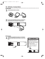
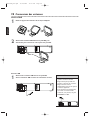
16 Antenna Connections
AM Antenna
1
Fix the antenna holder as shown.
2
Connect the supplied AM antenna to the AM jack,
then position it to receive the clearest sound.
FM Antenna
1
Connect the supplied FM antenna to the FM jack.
Extend the FM antenna wire and fix its end to the
wall.
VIDEO
TV ANTENNA
AUDIO
R L
PROGRESSIVE
OUT
IN
ANTENNA 75Ω
ANTENNA 75Ω
Y
Pb/Cb
Pr/Cr
FM
(75Ω)
DIGITAL
AUDIO OUT
COAXIAL
S-VIDEO
OUT
VCR
IN
DVD/
VCR
OUT
COMPONENT
VIDEO OUT
AM
FL
FR
C
SL
SR
W
SPEAKER (4Ω)
P I
VIDEO
TV ANTENNA
AUDIO
R L
PROGRESSIVE
OUT
IN
ANTENNA 75Ω
ANTENNA 75Ω
Y
Pb/Cb
Pr/Cr
FM
(75Ω)
DIGITAL
AUDIO OUT
COAXIAL
S-VIDEO
OUT
VCR
IN
DVD/
VCR
OUT
COMPONENT
VIDEO OUT
AM
FL
FR
C
SL
SR
W
SPEAKER (4Ω)
P I
• Do not place the AM antenna on
the System.Keep it as far as
possible from the System and the
speaker wires.Keep it away from
the AC power cords of the System
and other equipment.
•For better FM reception,connect
an outdoor FM antenna (not
supplied) to the ANTENNA 75
ohm jack.
Helpful Hints
VIDEO
TV ANTENNA
AUDIO
R L
PROGRESSIVE
OUT
IN
ANTENNA 75Ω
ANTENNA 75Ω
Y
Pb/Cb
Pr/Cr
FM
(75Ω)
DIGITAL
AUDIO OUT
COAXIAL
S-VIDEO
OUT
VCR
IN
DVD/
VCR
OUT
COMPONENT
VIDEO OUT
AM
FL
FR
C
SL
SR
W
SPEAKER (4Ω)
P I
MX5100VR.qxd 6/04/2004 3:37 PM Page 16

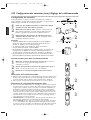
Speaker Setup 17
VIDEO
TV ANTENNA
AUDIO
R L
PROGRESSIVE
OUT
IN
ANTENNA 75Ω
ANTENNA 75Ω
Y
Pb/Cb
Pr/Cr
FM
(75Ω)
DIGITAL
AUDIO OUT
COAXIAL
S-VIDEO
OUT
VCR
IN
DVD/
VCR
OUT
COMPONENT
VIDEO OUT
AM
FL
FR
C
SL
SR
W
SPEAKER (4Ω)
P I
Center Speaker
Subwoofer
Front
Speaker
(left)
Rear Speaker
(left surround)
Rear Speaker
(right surround)
Front
Speaker
(right)
FL (Front Left - white)
FR (Front Right - red)
C (Center - green)
SL (Surround/Rear Left - blue)
SR (Surround/Rear Right - grey)
W (Subwoofer - purple)
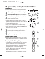
Connecting the speaker wires to the speaker jacks
1
Connect the supplied speakers using the supplied speaker
wires.Match the colors of the wires to the colors on the
jacks.
Hold down the jack tab while inserting the stripped
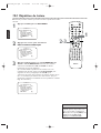
portion of the speaker wire into the jack.Then, release
the tab.Make sure you do not insert the wire too far. None
of the rubber-coated wire should be clamped by the jack tab.
Setting up Surround Sound
Connect all the speakers and set up the System properly in order to
enjoy the Home Cinema experience.
1
Place the FRONT Left and Right speakers at equal distances
from the TV and at a 45-degree angle from the listening
position.
2
Place the CENTER speaker above or below the TV to localize
the sound.
3
Place the REAR (Surround) speakers at normal listening ear
level,facing each other or mounted on the wall. Use the
supplied mounting brackets to mount speakers to the wall.
4
Place the Subwoofer on the floor,near the TV.
VIEWING AREA
Center Speaker
Subwoofer
Front
Speaker
(left)
Rear Speaker
(left surround)
Rear Speaker
(right surround)
Front
Speaker
(right)
TV
• Connect the speaker wires
correctly. Improper connections
may short circuit the System.
•For optimal sound,use the
supplied speakers.
• Do not connect more than one
speaker to any pair of speaker
jacks on the System.
• Do not connect speakers with an
impedance lower than 6 ohms.
• Sit in your usual listening position
to set up the speaker balance.
Details are on pages 52-53.
•To avoid magnetic interference,do
not place the FRONT speakers too
close to your TV.
• Placing the REAR (Surround)
speakers farther from the listening
position than the FRONT and
CENTER speakers will weaken the
Surround Sound effect.
• Secure all speakers to prevent
accidents and improve sound
quality.Use the supplied mounting
brackets to mount speakers to a
wall.Details are on page 18.
Helpful Hints
MX5100VR.qxd 6/04/2004 3:37 PM Page 17

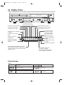
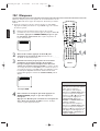
18 Speaker Setup (cont’d), Remote Control Setup
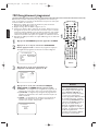
Putting Batteries in the Remote Control
1
Remove the battery compartment lid on the bottom of
the remote control by pressing the tab,then lifting the lid.
2
Place two AA batteries inside the battery
compartment with their +and – ends aligned as indicated.
3
Replace the battery compartment lid.
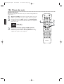
Using the Remote Control
● Point the remote control at the System’s remote sensor (marked
IR,see page 24) when using the remote to operate the System.Do
not point the remote at the TV.
● Do not put objects between the remote and the System.
Recycling Guidelines/Battery Safety
●
Your new product and its packaging contain materials that can be
recycled and reused. Specialized companies can recycle your product
to increase the amount that needs to be properly disposed.Your
product uses batteries that should not be thrown away when depleted
but should be disposed of as small chemical waste. Please find out
about the local regulations on disposal of your old product,batteries,
and packaging whenever you replace existing equipment.
● Battery Usage CAUTION - To prevent battery leakage that may
result in bodily injury, property damage,or damage to the unit:
Install ALL batteries correctly, with the + and - markings on the
battery aligned as indicated on the unit;
Do not mix batteries,for example, old with new or carbon with
alkaline;and
Remove batteries when the unit will not be used for a long time.
1
2
3
Speaker setup
You can hang the front,center and rear (Surround) speakers on a
wall.Each speaker needs one screw (not supplied) for mounting.
Use the type and size of screw as shown at right.
1
Attach a supplied bracket to the back of each speaker
with one of the supplied screws.
2
Drive a screw into the wall. Make sure the screw and the
wall can support 11 lbs. (5 Kg.) Drive the screw until the
screw head extends about 0.1” (3.5 mm) from the wall.
3
Hook the slot in the speaker’s bracket onto the wall-
mounted screw. Tuck the extra speaker wire into the
recessed area behind the speaker.
Caution
• Check the stability of the ceiling or wall. Philips is not liable for
accidents caused by insufficient stability of the ceiling or wall or for
improper mounting.
• The speaker may fall due to unstable mounting.
• If you need assistance, contact Philips.
• Do not modify or change the fittings of the supplied speakers,
mounting brackets,and screws.Use these brackets to mount the
supplied speakers only. Do not load anything else on these fittings.
• Do not step on or hang from the speakers. Pay special attention to
small children to ensure their safety.
1
2
3
MX5100VR.qxd 6/04/2004 3:37 PM Page 18

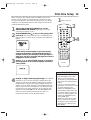
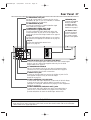
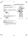
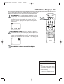
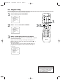
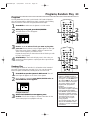
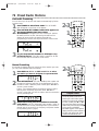
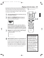
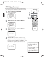
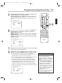
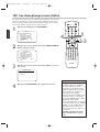
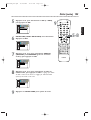
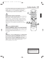
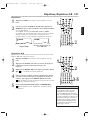
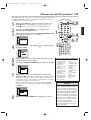
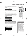
First-time Setup 19
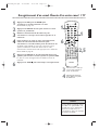
Before turning on your System,make sure batteries are in the
remote control and the TV and System are connected correctly.
You cannot program TV channels at the System if you are using a
Cable Box or a Satellite Receiver.You will change channels at the
Cable Box/Satellite Receiver.
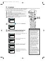
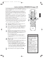
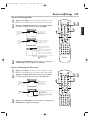
1
Turn on the TV. Set it to channel 3 or 4 or its
AUDIO/VIDEO IN channel, depending on how you
connected the System to a TV.
2
Press STANDBY-ON
yy
to turn on the System, then
press VCR. The red VCR light and the red STANDBY-ON
light will appear on the front of the System.This display will
appear.
These menus may not appear if you have already
turned on the System (to find the Audio/Video In
channel of the TV, for example). Follow the steps on
page 28 to set up TV channels and page 32 to select a
language for the VCR menus.
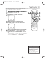
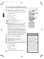
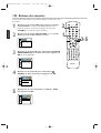
3
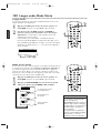
Press o or p to select English, French,or Spanish as
the language for VCR on-screen displays and menus.
Then, press B.
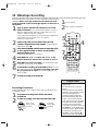
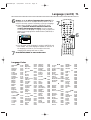
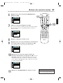
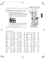
4
Press B to begin channel programming. AUTO SETUP
will flash on the TV screen during the channel search.The
System will memorize all available channels.When channel
programming is complete,the lowest available channel will
appear on the TV.These channels will be available when you
want to watch TV while the System is in VCR mode.To put
the System in VCR mode,press VCR so the red VCR light
appears.Use the SKIP i /CH o and SKIP j /CH p
buttons to select memorized channels.To select non-
memorized channels,use the Number buttons.
B
•To skip this feature and play a
tape immediately,insert a tape
with its record tab removed.
•To skip step 3, press DISC/MENU.
VCR menus and displays will be in
English.
• If you try to program channels
when there is no antenna or Cable
TV signal connected to the
System’s TV ANTENNA IN jack,
programming will stop.AUTO SET
UP will stop flashing.Connect an
antenna or Cable TV signal to the
System’s TV ANTENNA IN jack
and press B again.
• Repeat this process if the power
fails for more than 30 seconds.
•To stop the Channel Setup while
AUTO SET UP is flashing, press
DISC/MENU.
Helpful Hints
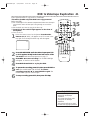
STANDBY-ON
TIMER SET
VCR/TV
SEARCH MODE
REPEAT
TUNER
3
456
789
SLOW
0
+10
2
1
VCRDVD
CLEAR
DISPLAY
SETUP/
PROG
TITLE RETURNMODE/SPEED
C-RESET
AUDIO/
BAND
ANGLE
SUBTITLE
ZOOM
DISC
MENU
OK
PAUSE
REW FF
PLAYSTOP
SKIP/
CH
SKIP/
CH
REPEAT
SOUNDSURROUND
+–
VOLUME
REC
A-B
PHILIPS
1
Turn on the TV.
2
3-4
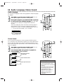
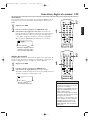
MX5100VR.qxd 6/04/2004 3:37 PM Page 19

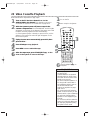
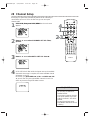
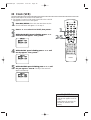
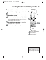
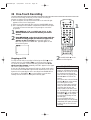
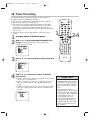
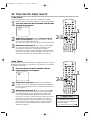
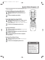
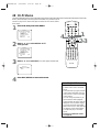
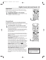
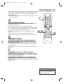
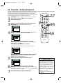
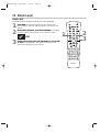
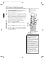
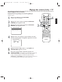
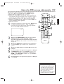
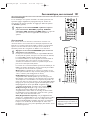
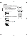
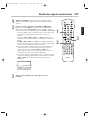
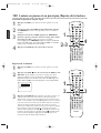
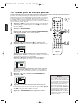
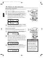
20 Video Cassette Playback
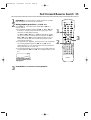
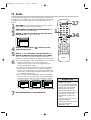
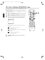
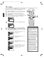
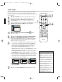
Read and follow the steps below to play a tape.
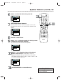
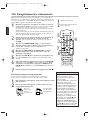
1
Turn on the TV. Set it to channel 3 or 4 or its
AUDIO/VIDEO IN channel.This depends on how you
connected the System to a TV. Details are on pages 8-11.
2
With the System’s power off, insert a tape in the
cassette compartment. The STANDBY-ON and VCR lights
will appear on the front of the System.If the tape’s record tab
has been removed,playback will start automatically.
Or,if the System’s power is already on,press VCR to put the
System in VCR mode.The red VCR light will appear on the
front of the System.
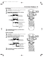
3
If play does not start automatically, press VCR, then
press PLAY B.
4
Press STOP C to stop playback.
5
Press REW h to rewind the tape.
6
After the tape stops,press STOP/EJECT C A on the
front of the System to remove the tape.
• Other tape playback features are
on pages 42-46.
• If AUTO REPEAT is ON,playback
will begin when you insert a tape,
even when the record tab is intact.
Details are on page 42.
•You must connect the System to a
TV using the RF coaxial cable or
the audio/video cables in order to
use the VCR features.These
hookups are explained on pages
eight and 11.
•You cannot use the VCR when the
System is in Tuner mode.If you fast
forward,rewind,or eject a videotape,
you may hear noise through the
speakers or some displays may be
incorrect.
•You cannot use the Tuner when the
System is in VCR mode.Make sure
you stop tape play before putting
the System in Tuner mode.
Helpful Hints
STANDBY-ON
TIMER SET
VCR/TV
SEARCH MODE
REPEAT
TUNER
3
456
789
SLOW
0
+10
2
1
VCRDVD
CLEAR
DISPLAY
SETUP/
PROG
TITLE RETURNMODE/SPEED
C-RESET
AUDIO/
BAND
ANGLE
SUBTITLE
ZOOM
DISC
MENU
OK
PAUSE
REW FF
PLAYSTOP
SKIP/
CH
SKIP/
CH
REPEAT
SOUNDSURROUND
+–
VOLUME
REC
A-B
1
Turn on the TV.
2
Insert a tape in the System.
3
6
Press STOP/EJECT C A on
the System.
4
5
MX5100VR.qxd 6/04/2004 3:37 PM Page 20
La page est en cours de chargement...
La page est en cours de chargement...
La page est en cours de chargement...
La page est en cours de chargement...
La page est en cours de chargement...
La page est en cours de chargement...
La page est en cours de chargement...
La page est en cours de chargement...
La page est en cours de chargement...
La page est en cours de chargement...
La page est en cours de chargement...
La page est en cours de chargement...
La page est en cours de chargement...
La page est en cours de chargement...
La page est en cours de chargement...
La page est en cours de chargement...
La page est en cours de chargement...
La page est en cours de chargement...
La page est en cours de chargement...
La page est en cours de chargement...
La page est en cours de chargement...
La page est en cours de chargement...
La page est en cours de chargement...
La page est en cours de chargement...
La page est en cours de chargement...
La page est en cours de chargement...
La page est en cours de chargement...
La page est en cours de chargement...
La page est en cours de chargement...
La page est en cours de chargement...
La page est en cours de chargement...
La page est en cours de chargement...
La page est en cours de chargement...
La page est en cours de chargement...
La page est en cours de chargement...
La page est en cours de chargement...
La page est en cours de chargement...
La page est en cours de chargement...
La page est en cours de chargement...
La page est en cours de chargement...
La page est en cours de chargement...
La page est en cours de chargement...
La page est en cours de chargement...
La page est en cours de chargement...
La page est en cours de chargement...
La page est en cours de chargement...
La page est en cours de chargement...
La page est en cours de chargement...
La page est en cours de chargement...
La page est en cours de chargement...
La page est en cours de chargement...
La page est en cours de chargement...
La page est en cours de chargement...
La page est en cours de chargement...
La page est en cours de chargement...
La page est en cours de chargement...
La page est en cours de chargement...
La page est en cours de chargement...
La page est en cours de chargement...
La page est en cours de chargement...
La page est en cours de chargement...
La page est en cours de chargement...
La page est en cours de chargement...
La page est en cours de chargement...
La page est en cours de chargement...
La page est en cours de chargement...
La page est en cours de chargement...
La page est en cours de chargement...
La page est en cours de chargement...
La page est en cours de chargement...
La page est en cours de chargement...
La page est en cours de chargement...
La page est en cours de chargement...
La page est en cours de chargement...
La page est en cours de chargement...
La page est en cours de chargement...
La page est en cours de chargement...
La page est en cours de chargement...
La page est en cours de chargement...
La page est en cours de chargement...
La page est en cours de chargement...
La page est en cours de chargement...
La page est en cours de chargement...
La page est en cours de chargement...
La page est en cours de chargement...
La page est en cours de chargement...
La page est en cours de chargement...
La page est en cours de chargement...
La page est en cours de chargement...
La page est en cours de chargement...
La page est en cours de chargement...
La page est en cours de chargement...
La page est en cours de chargement...
La page est en cours de chargement...
La page est en cours de chargement...
La page est en cours de chargement...
La page est en cours de chargement...
La page est en cours de chargement...
La page est en cours de chargement...
La page est en cours de chargement...
La page est en cours de chargement...
La page est en cours de chargement...
La page est en cours de chargement...
La page est en cours de chargement...
La page est en cours de chargement...
La page est en cours de chargement...
La page est en cours de chargement...
La page est en cours de chargement...
La page est en cours de chargement...
La page est en cours de chargement...
La page est en cours de chargement...
La page est en cours de chargement...
La page est en cours de chargement...
La page est en cours de chargement...
La page est en cours de chargement...
La page est en cours de chargement...
La page est en cours de chargement...
La page est en cours de chargement...
La page est en cours de chargement...
La page est en cours de chargement...
La page est en cours de chargement...
La page est en cours de chargement...
La page est en cours de chargement...
La page est en cours de chargement...
La page est en cours de chargement...
La page est en cours de chargement...
La page est en cours de chargement...
La page est en cours de chargement...
La page est en cours de chargement...
La page est en cours de chargement...
La page est en cours de chargement...
La page est en cours de chargement...
La page est en cours de chargement...
La page est en cours de chargement...
La page est en cours de chargement...
La page est en cours de chargement...
La page est en cours de chargement...
La page est en cours de chargement...
La page est en cours de chargement...
La page est en cours de chargement...
La page est en cours de chargement...
La page est en cours de chargement...
La page est en cours de chargement...
La page est en cours de chargement...
La page est en cours de chargement...
-
 1
1
-
 2
2
-
 3
3
-
 4
4
-
 5
5
-
 6
6
-
 7
7
-
 8
8
-
 9
9
-
 10
10
-
 11
11
-
 12
12
-
 13
13
-
 14
14
-
 15
15
-
 16
16
-
 17
17
-
 18
18
-
 19
19
-
 20
20
-
 21
21
-
 22
22
-
 23
23
-
 24
24
-
 25
25
-
 26
26
-
 27
27
-
 28
28
-
 29
29
-
 30
30
-
 31
31
-
 32
32
-
 33
33
-
 34
34
-
 35
35
-
 36
36
-
 37
37
-
 38
38
-
 39
39
-
 40
40
-
 41
41
-
 42
42
-
 43
43
-
 44
44
-
 45
45
-
 46
46
-
 47
47
-
 48
48
-
 49
49
-
 50
50
-
 51
51
-
 52
52
-
 53
53
-
 54
54
-
 55
55
-
 56
56
-
 57
57
-
 58
58
-
 59
59
-
 60
60
-
 61
61
-
 62
62
-
 63
63
-
 64
64
-
 65
65
-
 66
66
-
 67
67
-
 68
68
-
 69
69
-
 70
70
-
 71
71
-
 72
72
-
 73
73
-
 74
74
-
 75
75
-
 76
76
-
 77
77
-
 78
78
-
 79
79
-
 80
80
-
 81
81
-
 82
82
-
 83
83
-
 84
84
-
 85
85
-
 86
86
-
 87
87
-
 88
88
-
 89
89
-
 90
90
-
 91
91
-
 92
92
-
 93
93
-
 94
94
-
 95
95
-
 96
96
-
 97
97
-
 98
98
-
 99
99
-
 100
100
-
 101
101
-
 102
102
-
 103
103
-
 104
104
-
 105
105
-
 106
106
-
 107
107
-
 108
108
-
 109
109
-
 110
110
-
 111
111
-
 112
112
-
 113
113
-
 114
114
-
 115
115
-
 116
116
-
 117
117
-
 118
118
-
 119
119
-
 120
120
-
 121
121
-
 122
122
-
 123
123
-
 124
124
-
 125
125
-
 126
126
-
 127
127
-
 128
128
-
 129
129
-
 130
130
-
 131
131
-
 132
132
-
 133
133
-
 134
134
-
 135
135
-
 136
136
-
 137
137
-
 138
138
-
 139
139
-
 140
140
-
 141
141
-
 142
142
-
 143
143
-
 144
144
-
 145
145
-
 146
146
-
 147
147
-
 148
148
-
 149
149
-
 150
150
-
 151
151
-
 152
152
-
 153
153
-
 154
154
-
 155
155
-
 156
156
-
 157
157
-
 158
158
-
 159
159
-
 160
160
-
 161
161
-
 162
162
-
 163
163
-
 164
164
-
 165
165


Philips MX5100VR Manuel utilisateur
- Catégorie
- Lecteurs DVD
- Taper
- Manuel utilisateur
dans d''autres langues
- English: Philips MX5100VR User manual
