
POWRMAX
™
605
0419 • Form No. 2405629A / Doc. # 11310340
TEXTURE SPRAYER
PULVÉRISATEUR À TEXTURE
PULVERIZADOR DE TEXTURA
- EN - OPERATING MANUAL 2
- F - MODE D’EMPLOI 26
- ES - INSTRUCCIONES DE USO 50
OPERATING MANUAL

2
ORIGINAL OPERATING MANUAL
PowrMax
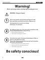
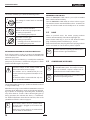
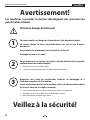
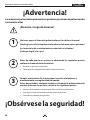
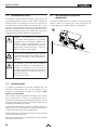
Warning!
Mortar spraying machines develop high spraying pressure.
Be safety conscious!
1
2
3
Never reach into the spray jet with your ngers or hand!
Never point the spray lance at yourself or other persons!
Coating materials are caustic or irritating!
Protect your skin and eyes!
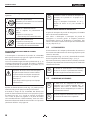
WARNING - Danger of injury!
The following points are to be observed in accordance with
the operating manual before every start-up:
1. Observe the permissible pressures.
2. Check all the connecting parts for leaks.
Instructions for regular cleaning and maintenance of the ma-
chine are to be observed strictly.
Observe the following point before any work on the machine
and at every working break:
1. Observe the curing time of the coating material.
2. Depressurize the spray lance and mortar hose.
3. Switch o the suction pump.

3
CONTENTS
PowrMax
1 SAFETY REGULATIONS ___________________ 4
1.1 Explanation of symbols used _____________________4
1.2 Electric safety _________________________________6
1.3 Machine usage ________________________________6
1.4 Setup on an uneven surface _____________________6
2 INTRODUCTION TO WORKING WITH THE
MORTAR SPRAYING MACHINE
POWRMAX 605 __________________________ 7
2.1 Function overview of the mortar spraying machine
PowrMax 605 _________________________________7
2.2 Processible coating materials ____________________7
3 TECHNICAL DATA ________________________ 8
4 EXPLANATORY DIAGRAM FOR
POWRMAX 605 __________________________ 8
4.1 Operating elements and displays on device ________8
4.2 Drive _______________________________________10
4.3 Compressor (accessory) ________________________ 10
4.4 Mortar hose _________________________________11
4.5 Spray lance __________________________________11
5 TRANSPORTATION ______________________ 12
5.1 Moving _____________________________________12
5.2 Transport using a crane (g. 4) __________________12
5.3 Transportation in vehicle _______________________12
6 COMMISSIONING _______________________ 12
6.1 Installation location ___________________________12
6.1.1 Connection to mains power supply/ Extension cable 12
6.2 Initial starting-up _____________________________12
6.2.1 Scope of supply ______________________________12
6.2.2 Assembly (g. 5) ______________________________ 13
6.3 Connecting the mortar hose ____________________13
6.4 Compressor (accessory) ________________________ 13
6.5 Spray attachment assembly (accessories) _________14
6.6 Connecting the spray lance (g. 10) ______________14
6.7 Preparing the mortar spraying machine (g. 12) ____15
6.7.1 Rinse the mortar hose _________________________ 15
6.8 Beginning of the spraying process _______________16
6.9 End of the spraying process ____________________16
7 GENERAL INFORMATION ABOUT THE
APPLICATION TECHNIQUE _______________ 17
7.1 Spraying technique ___________________________17
8 SHUTTING DOWN AND CLEANING ________ 17
8.1 Cleaning the mortar hose ______________________17
8.2 Cleaning the device and replacing the stator_______18
8.3 Cleaning the spray lance _______________________19
9 MAINTENANCE _________________________ 20
9.1 Mechanical maintenance ______________________20
9.2 Electrical maintenance ________________________20
9.3 Long periods of non-usage _____________________20
9.4 Shaft seal (g. 16) _____________________________20
9.5 Rotor replacement ____________________________21
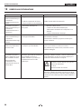
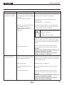
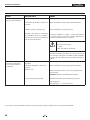
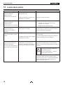
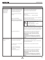
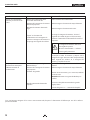
10 ELIMINATING FAULTS ________________ 2224
WARRANTY _________________________________ 25
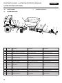
SPARE PARTS LIST FOR POWRMAX 605 ________ 74
Spare parts list for main assembly _____________________74
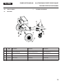
Spare parts list for frame ____________________________75
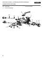
Spare parts list for spray lance _____________________ 76/77
ACCESSORIES ____________________________ 78/79

4
SAFETY PRECAUTIONS
PowrMax
1 SAFETY REGULATIONS
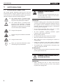
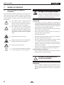
1.1
EXPLANATION OF SYMBOLS USED
This manual contains information that must be read and
understood before using the equipment. When you come to
an area that has one of the following symbols, pay particular
attention and make certain to heed the safeguard.
This symbol indicates a potential hazard
that may cause serious injury or loss of life.
Important safety information will follow.
At
tention
This symbol indicates a potential hazard
to you or to the equipment. Important
information that tells how to prevent
damage to the equipment or how to avoid
causes of minor injuries will follow.
Danger of skin injection
Danger of injury from inhalation of harmful
vapors
Danger of electric shock
i
Notes give important information which
should be given special attention.
WARNING: PROTECTION OF
PERSONS
Spray materials can be harmful if inhaled or come
in contact with body. Vapors can cause severe
nausea, fainting, or poisoning.
PREVENTION:
• Protective clothing, gloves and possibly skin protection
cream are necessary for the protection of the skin. Observe
the regulations of the manufacturer concerning coating
materials, solvents and cleaning agents in preparation,
processing and cleaning units.
• Do not remove the mortar hose as long as it is under
pressure. Pay attention to the pressure gauge.
• All local regulations regarding protection against
hazardous vapors must be observed.
• Wear protective eyewear.
• Do not point the spray lance at persons or animals.
• Wear ear protection in order to protect your ears.
• Wear safety shoes when transporting the machine or
working with it.
• People not needed to assist with machine installation,
assembly or operation, must keep away from the machine.
• The PowrMax 605 is equipped with an Emergency Stop
switch for emergency shuto.
Breathing masks:
• Make a breathing mask available to the operator in order to
protect against mineral dust.
WARNING: RISK OF INJURY DUE TO
ESCAPING MATERIAL
PREVENTION:
• Before switching the unit on, always check that the
material tap on the spray lance is closed. Close material
tap whenever stopping work.

5
SAFETY PRECAUTIONS
PowrMax
WARNING: RISK OF INJECTION
INJURY THROUGH LEAKING HIGH
PRESSURE HOSE
Wear and tear and links as well as usage that is
not appropriate to the purpose of the device can
cause leakages to form in the mortar hose. Liquid
can be injected into the skin through a leakage.
PREVENTION:
• Mortar hoses must be checked thoroughly before they are
used.
• Replace any damaged mortar hose immediately.
• Never repair defective mortar hoses yourself!
• Avoid sharp bends and folds: the smallest bending radius
is about 80 cm.
• Do not drive over the mortar hose. Protect against sharp
objects and edges.
• Never pull on the mortar hose to move the device.
• Do not twist the mortar hose.
• Lay the mortar hose in such a way as to ensure that it
cannot be tripped over.
i
Only use TITAN original-mortar hoses in order to
ensure functionality, safety and durability.
i
The risk of damage rises with the age of the
mortar hose.
TITAN recommends replacing mortar hoses after
6 years.
WARNING: RISK OF INJURY DUE TO
MOVING PARTS
PREVENTION:
• Never operate the mortar spraying machine if the rotor is
exposed or if the container has been removed.
• Do not reach into the rotor when it is moving. Risk of
crushing. Caution if you have long hair. Only wear close-
tting clothes at work. Do not insert objects or body parts
through the protective grid.
• Risk of crushing when folding in the handles, assembling
the pump unit and connecting the mortar hose.
HAZARD: GENERAL
This product can cause severe injury or property
damage.
PREVENTION:
• Never decouple mortar hose or disassemble machine when
under pressure. Note pressure reading on pressure gauge.
• When performing maintenance work, always switch o
mortar spraying machine, disconnect mains plug and
ensure it cannot be plugged back in by mistake.
• Do not spray down the motor and control unit of the
mortar spraying machine with a water-jet, high-pressure
cleaner or high-pressure steam cleaner. Danger of short-
circuits caused by water ingressing.

6
SAFETY PRECAUTIONS
PowrMax
1.2 ELECTRIC SAFETY
Electric models must be grounded (earthed). In the event of
an electrical short circuit, grounding (earthing) reduces the risk
of electric shock by providing an escape wire for the electric
current. This product is equipped with a cord having an
earthing wire with an appropriate earthing plug. Connection to
the mains only through a special feed point, e.g. through an
error protection insallation with INF < 30 mA.
DANGER — Work or repairs at the electrical
equipment may only be carried out by a skilled
electrician. No liability is assumed for incorrect
installation. Switch the unit o. Before all repair
work, unplug the power plug from the outlet.
Danger of short-circuits caused by water
ingressing into the electrical equipment. Never
spray down the unit with high-pressure or high-
pressure steam cleaners.
Whenever the machine is automatically brought
to a standstill or during power failure, immediately
move the selector switch to “A” to prevent the
machine starting back up again unintentionally.
There is a danger of injury.
1.3 MACHINE USAGE
The mortar spraying machine PowrMax 605 may only be used
to process the coating materials described on page 7. Any
other usage is not allowed.
Proper usage also includes the observance of the operating
manual and the observance of the inspection and maintenance
conditions. Always keep the operating manual on hand at the
point of use of the mortar spraying machine.
The mortar spraying machine PowrMax 605 may only be
operated with a manometer. Only the mortar hose specied by
the manufacturer may be used.
Use only marked mortar hoses with at least 40 bars operating
pressure.
The mortar spraying machine is intended exclusively for
commercial use by professionals.
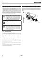
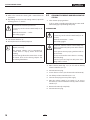
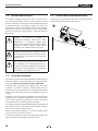
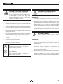
1.4 SETUP ON AN UNEVEN SURFACE
The mortar spraying machine must be installed as shown in the
diagram below to prevent it slipping. Block front wheels with
brakes.

7
INTRODUCTION
PowrMax
2 INTRODUCTION TO WORKING WITH
THE MORTAR SPRAYING MACHINE
POWRMAX 605
The suction pump PowrMax 605 is conceived for using and
processing ready mixed mineral coating materials.
The machine is not designed for use as a cleaning device.
2.1 FUNCTION OVERVIEW OF THE MORTAR
SPRAYING MACHINE POWRMAX 605
The coating material is supplied by means of the container.
The spiral conveyor feeds the coating material to the eccen-
tric screw pump. The suction eect causes the coating material
to enter the eccentric screw pump. This pump builds up the
pressure required for transportation through the mortar hose.
The compressed air required for atomisation is supplied at the
spray lance. The mortar spraying machine can be switched
on and o using the electric control. This can also be used to
control the delivery volume.
A soft even spray pattern can be achieved by means of the
smoothly regulated convey capacity of the coating material.
2.2 PROCESSIBLE COATING MATERIALS
• Thermal insulation composite system bonding agent
(mineral and articial resin systems)
• Articial resin plasters up to 6 mm granular size
• Silicate plasters up to 6 mm granular size
• Silicone resin plasters up to 6 mm granular size
• Mineral nal coats up to 6 mm granular size
• Lightweight plaster systems up to 6 mm granular size
• Scraped stucco up to 6 mm granular size
• Thermal insulation plasters
• Restoration plaster
• Porous concrete coating
• Quartz plastic
• Roof coatings
• Fire protection coatings
• Mineral sealing sludges
• Bitumen emulsions
• Armoring ller
• Liquid wood-chip wall paper
• Casement grouting mortar
• Articial resin rendering base
• Wash primer
• Filling paint, also brous
• Elastic coating
• Acoustic plaster, articial resin bonded
• Fillers, articial resin bonded
All the coating materials must be suitable for machine
processing. Refer to the product data sheet of the coating
material to be processed.
Use other coating materials only after agreement with the
manufacturer or the TITAN application technology service.

8
TECHNICAL DATA / EXPLANATORY DIAGRAM
PowrMax
3 TECHNICAL DATA
PowrMax 605
Voltage: 230 V~, 50/60 Hz
Fusing: 16 A time-lag
Device supply cable: 5 m long, 3 x 2.5 mm
2
Motor output P
1
: 2.3 kW
Max. convey capacity (water): 10, 15, 20 l/min
(depending on the rotor/
stator)
Max. operating pressure: 40 bar
Max. granular size: K6 mm
Dimensions L x W x H: 1150 x 520 x 610 mm
Container capacity: 50 l
Weight (PowrMax 605): 59 kg
Weight (Spray lance): 2.1 kg
Max. tyre pressure: 2.5 bar
Degree of protection: IP 54
Max. sound pressure level: 70 dB (A)*
Atomizing air connection: Rapid action coupling
DN 7.2 mm
Max. atomizing air pressure: 10 bar
Minimum required compressed
air volume:
320 l/min
Max. mortar hose length: 40 m (and 2.5 m hose
whip)
Max. delivery height: 20 m
* Place of measurement: 1 m distance from unit and 1.60 m
above reverberant oor.
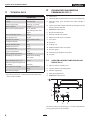
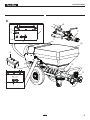
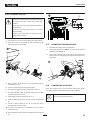
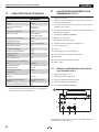
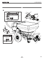
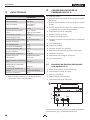
4 EXPLANATORY DIAGRAM FOR
POWRMAX 605 FIG. 2
1. Control unit
2. Indicator light red (indicates the presence of a malfunction)
3. Operating light green (indicates that mains voltage is
present)
4. Control panel with selector switch for operating mode and
delivery volume controller
5. EMERGENCY STOP switch
6. Base frame with wheels
7. External controller connection
8. Mortar hose with air hose complete
9. Spray lance
10. Container
11. Loading area
12. Outlet unit with inside screw pump
13. Pressure gauge
14. Connecting coupling for mortar hose
15. Tool box
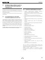
4.1 OPERATING ELEMENTS AND DISPLAYS ON
DEVICE FIG. 3
1. Delivery volume controller 0-10
2. Selector switch for operating mode
3. Indicator light (Error)
4. Operating light (Power)
5. EMERGENCY STOP switch
POWER
ERROR
SPEED
R
A
F
2
1
4
3
5
The delivery volume controller (Fig. 3, 1) is used to regulate the
convey capacity from 0-10 smoothly.

9
EXPLANATORY DIAGRAM
PowrMax
POWER
ERROR
SPEED
R
A
F
1
5
4
REMOTE
Control
ELEC
PNEUM
Controler
2
3
6
7
8
9
10
12
13
14
15
11

10
EXPLANATORY DIAGRAM
PowrMax
The selector switch (Fig. 3, 2) oers the following modes:
A
R
F
“A” position = automatic
Basic setting for control with an automatic
spray lance
A
R
F
“F” position = manual activation
Switches on the mortar spraying machine.
This setting is required for:
• disassembling the pump unit
A
R
F
“R” position = reverse gear
This setting is required for:
• relieving pressure on the mortar hose
• assembling the pump unit
DETAILED EXPLANATION OF SELECTOR SWITCH USE:
If the selector switch is in the “A” position, the PowrMax 605
can be switched on and o with the material shut-o on the
automatic spray lance.
If there is no spray lance tted (e.g.: assembly/disassembly the
pump unit ), the machine is switched on using the “F” switch
position and o using the “A” position.
Important: control via the selector switch and
material shut-o are treated equally.
The machine can be switched from the “A”
position (control using material shut-o) to “F” at
any time.
We would therefore recommend that only one
person operate the machine.
The operating light (green, Fig. 3, 4) indicates that the machine
is energised and ready.
When the mains plug is connected the PowrMax 605 carries out
a function check. While this is going on the indicator light (red,
g. 3.3) ashes. If everything is in working order, the ashing
stops after about 30 seconds. If the indicator light lights up
during operation, this indicates that there is a malfunction.
For detailed information about this kind of fault, refer to the
„Rectication of faults“ section on page 22.
i
If the selector switch is in the “F” position when
the mains plug is plugged in, the machine will
not switch on.
Briey move selector switch to “A” and then back
to “F” to switch on the machine.
EMERGENCY STOP SWITCH
When the EMERGENCY STOP switch is pressed, the PowrMax
605 is switched o immediately.
Turn the EMERGENCY STOP switch in order to release it again.
The machine remains switched o after release. To switch it on
again, the selector switch must be briey set to “A” and then
to “F”.
4.2 DRIVE
When an overload occurs, the mortar spraying machine
switches o automatically (red indicator light lights up).
Move selector switch (Fig. 3, 2) to “A” and disconnect mains
plug. Set delivery volume controller (Fig. 3, 1) to „0“.
Wait around 5 minutes, then plug the mortar spraying machine
back in and switch on. Set the delivery volume required.
i
The drive unit heats up during operation. This is
normal and not a sign of malfunction.
4.3 COMPRESSOR ACCESSORY
i
An air compressor must be used to provide air to
the PowrMax 605 system. The compressor must
have the minimum required compressed air
volume listed in the Technical Data section.
i
Only operate the compressor in accordance with
the enclosed operating manual.

11
EXPLANATORY DIAGRAM
PowrMax
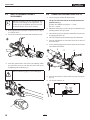
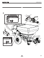
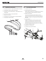
4.4 MORTAR HOSE
1. Material connection mortar spraying machine
2. Control cable connection / controller
3. Atomizing air connection compressed air supply
4. Material connection spray lance
5. Mortar hose
6. Atomizing air connection spray lance
7. Control cable connection
3
2
1
7 6 5
4
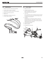
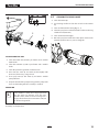
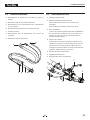
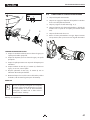
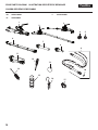
4.5 SPRAY LANCE
1. Material connection
2. Combined material and air tap:
Open: material tap at 90° to spray lance
Closed: material tap points forwards
3. Texture tip:
Various texture tips can be used in the spray lance. The tip
size depends on the granular size of the coating material
and the desired spray pattern.
4. Hand-grip:
The hand-grip can mounted to either the right or left
side of the spray lance, depending on what is required.
The thread on the other side can be closed by way of the
attached stoppers for protection.
5. Control cable connection
6. Air ow regulator
7. Atomization air connection
1
2
3
4
5
6
7

12
TRANSPORTATION / COMMISSIONING
PowrMax
5 TRANSPORTATION
5.1
MOVING
Wind power cable around handle and remove the hose.
Put away the nozzles and other small objects in the storage
compartment.
Push or pull the PowrMax 605 by the handle.
Make sure that 2 people are available to carry the
device on stairs.
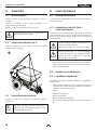
5.2 TRANSPORT USING A CRANE FIG. 4
For attaching points for the straps or rope (not wire cable) see
figure.
5.3 TRANSPORTATION IN VEHICLE
Secure the unit in the vehicle by means of suitable fasteners.
i
To avoid material residues leaking from the
machine, clean the device in advance or lock the
mortar connection.
6 COMMISSIONING
6.1
INSTALLATION LOCATION
Position mortar spraying machine in a level position to prevent
it from sliding away.
6.1.1 CONNECTION TO MAINS POWER SUPPLY/
EXTENSION CABLE
Connection to the mains network only via a special feeding
point, for example via a distribution board for construction
sites, with residual current protective device with INF ≤ 30 mA.
Lay the device supply cable so that there is no
danger of stumbling.
Protect against damage, for example against
being driven over.
At
tention
Min. wire cross-section 3 x 2.5 mm. Unroll the
extension cable completely. Ensure that the
coupling pieces and plugs are free of damage.
• Before connecting the unit to the mains supply, ensure
that the line voltage matches that specied on the rating
plate.
6.2 INITIAL STARTINGUP
6.2.1 SCOPE OF SUPPLY
The machine is supplied by the manufacturer in the following
individual components:
• Complete basic machine comprising drive unit, control
unit, receptacle and transport frame with wheels
• Stator
• Hose package
• Spray lance
• Pump sliding means
• Tool box with nozzles, cleaning accessories,...

13
COMMISSIONING
PowrMax
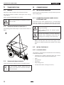
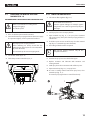
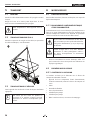
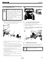
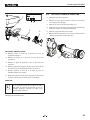
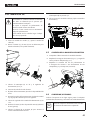
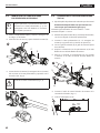
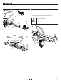
6.2.2 ASSEMBLY FIG. 5/6
Disconnect external controls. Assembly may only
be carried out by the person who controls the
machine.
Never operate mortar spraying machine with an
exposed rotor.
Do not reach into the rotor when it is moving.
Risk of crushing.
Caution if you have long hair. Only wear close-
tting clothes at work.
1. Loosen the star screws (1) and remove the outlet unit (2).
2. Spray the stator (3) and rotor (4) with a suitable pump
lubricant (order no. 9992 824).
2
1
3
4
5
3
3. Move selector switch (6) to “A” and set delivery volume
controller (7) to „0“.
4. Connect mains plug to mains power supply.
5. The operation light (8) shows operational readiness.
6. The red indicator light (9) ashes during the function
check for about 30 seconds.
7. Set delivery volume controller (7) to 1 or 2.
8. Push the stator (3) over the tip of the rotor (4) (guide rail
(5)).
9. Set the selector switch (6) to „R“ to push the stator
automatically on to the rotor.
10. As soon as the stator is in end position, set the selector
switch (6) to „A“.
11. Re-assemble the outlet unit (2) and tighten the star screws
(1).
8
POWER
ERROR
SPEED
R
A
F
7
6
9
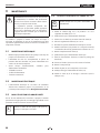
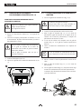
6.3 CONNECTING THE MORTAR HOSE
1. Check that the pump unit is seated rmly.
2. Connect the mortar hose (Fig. 7, 1) and secure it with the
clamping levers (Fig. 7, 2).
3. Connect the atomizing air connection at the mortar hose
to the compressed air supply, for example the compressor
(accessory).
2
1
6.4 COMPRESSOR ACCESSORY
Place the compressor at a secure location next to the mortar
spraying machine and connect it to the mains network.
i
Only operate the compressor in accordance with
the enclosed operating manual.

14
COMMISSIONING
PowrMax
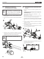
6.5 SPRAY ATTACHMENT ASSEMBLY
ACCESSORIES
i
Dierent accessories can be mounted to the
spray lance, depending on the application, e.g.
an extension can be attached. A precise overview
can be found in the “Accessories” chapter.
1. Disengage the quick connector and pull the air hose (g. 8,
1) out of the lance.
2. Loosen the locknut (2) and remove the material hose (3).
1
3
2
3. Insert the material hose and air hose (if available), which
are part of the accessory, into the spray lance and secure
by tightening the locknut. (Fig. 9)
At
tention
Make sure the O-ring (g. 9, 4) is not damaged.
4
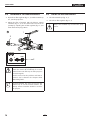
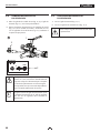
6.6 CONNECTING THE SPRAY LANCE FIG. 10
1. Select a spray tip suitable for the material:
The tip size should amount to at least three times the
granular size, e.g.
granular size articial resin plasters –> 3 mm
Tip size –> 10 mm
2. Mount the texture tip (1) in the spray lance with the cone
pointing towards the spray head.
3. Connect the spray lance (2) to the material hose and secure
by applying the levers (3).
4. Close the material tap (4) (material tap points forwards).
5. Connect atomization air connection (5) to the air hose of
the mortar hose.
6. Screw coupling plug (6) for remote control to the control
cable of the mortar hose.
2
4
1
3
6
5
7. Connect mortar hose‘s control cable to pump connection.
(Fig. 11)
8. Set selector switch to “A”.
REMOTE
Control
ELEC
PNEUM
Controler

15
COMMISSIONING
PowrMax
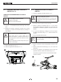
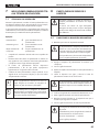
6.7 PREPARING THE MORTAR SPRAYING
MACHINE FIG. 12
RECOMMENDED SLIDING MEANS FOR THE MORTAR HOSE
At
tention
Water is not sucient as a sliding means.
Danger of clogging!
Use cellulose paste
1. Fill 2–3 l cellulose paste into the container.
2. Connect the mortar spraying machine to the mains supply.
The operation light (1) shows operational readiness.
Risk of injury from escaping material.
Before switching on, always check that the
material tap on the spray lance is closed (material
tap points forwards).
Close material tap whenever stopping work.
3. Set selector switch (2) to “A”.
4. Set delivery volume controller (3) to „3“.
1
2 3
6.7.1 RINSE THE MORTAR HOSE
1. Close the air ow regulator (g. 13.3).
At
tention
Do not bend the mortar hose!
Protect it against damage, for example against
being driven over as well as against sharp objects
and edges.
2. Hold spray lance over an empty bucket.
3. Open material tap (Fig. 13, 1) on spray lance (material
tap at 90° to spray lance), the mortar spraying machine is
switched on.
4. If cellulose paste comes out of the tip, close the material
tap (g. 13, 1) (material tap points forwards).
5. Fill coating material into the receptacle.
i
With mineral coating materials only fill the
receptacle to half full.
6. Position the spray lance over the bucket again.
7. Replace container and lubricant with container and
coating material.
8. Hold spray lance above container with cellulose paste.
9. Open material tap (Fig. 13, 1) on spray lance.
10. As soon as coating material exits from spray lance, close
material tap (Fig. 13, 1).
The mortar spraying machine is now full and ready.
1
3

16
COMMISSIONING
PowrMax
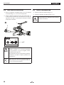
6.8 BEGINNING OF THE SPRAYING PROCESS
1. Open the air ow regulator (g. 13, 3) and the material tap
(13, 1) at the spray lance.
2. Adjust the ow of material with the delivery volume
controller (g. 13, 2) on the control unit and set the air
quantity by adjusting the air ow regulator (g. 13, 3) to
attain the desired spray pattern.
2
POWER
ERROR
SPEED
R
A
F
1
3
At
tention
Do not let the mortar spraying machine run dry.
Switch the device o immediately if no more
material comes out of the tip or if the spray line
becomes irregular.
Possible reasons for the problem and how to
correct it can be found in the chapter called
„Eliminating faults“.
i
Increased material tap wear. Do not use the
material tap to set the material volume. The
delivery volume controller should be used for
this purpose.
6.9 END OF THE SPRAYING PROCESS
1. Close the material tap (Fig. 13, 1).
2. Close the air ow regulator (g. 13, 3).
Always close material tap at end of the spray
process.

17
GENERAL INFORMATION ABOUT THE APPLICATION TECHNIQUE / SHUTTING DOWN AND CLEANING
PowrMax
7 GENERAL INFORMATION ABOUT THE
APPLICATION TECHNIQUE
7.1
SPRAYING TECHNIQUE
While spraying hold the spray lance at a uniform distance of
30 – 60 cm from the object. Otherwise the spray pattern will be
uneven.
The spray pattern depends on the coating material, viscosity,
tip size, convey capacity and amount of atomizing air.
Examples:
Fine texture
large amount of atomizing air
Rough texture
small amount of atomizing air
Higher convey
capacity
larger amount of atomizing air
• Test the desired texture on a test surface.
• The lateral limit of the spray jet should not be too sharp.
The distance between the spray lance and the object
should therefore be selected correspondingly.
• The spray edge should be gradual in order to facilitate
overlapping of the next coat.
• If the spray lance is moved parallel and at an angle of 90° to
the surface to be coated, the paint mist is minimized.
i
Grains and pigments with a sharp edge result
in a high rate of wear of the pump, mortar hose,
material tap and tip.
i
When using the mortar hose while working on
scaolding, it is best to always guide the hose
along the outside of the scaolding.
8 SHUTTING DOWN AND CLEANING
Do not clean the motor and control unit of the
mortar spraying machine moistly. And certainly
do not spray down the unit with high-pressure
cleaners or high-pressure steam cleaners. Danger
of short-circuits caused by water ingressing.
8.1 CLEANING THE MORTAR HOSE
1. Pump until receptacle is empty.
At
tention
Do not let the mortar spraying machine run dry.
Switch the device o immediately if no more
material comes out of the tip or if the spray line
becomes irregular.
Possible reasons for the problem and how to
correct it can be found in the chapter called
„Eliminating faults“.
2. Switch o mortar spraying machine and compressor.
3. Close material tap on spray lance.
4. Remove the texture tip from the spray lance and clean it.
5. Put water in the container and hold the spray lance over
an empty bucket.
At
tention
Do not let the mortar spraying machine run dry.
During the cleaning process, ensure that there is
always enough water in the container.
6. Set delivery volume controller to „5“.
7. Open material tap on spray lance.
8. Pump material out of hose into container until the material
exiting the hose is just a thin liquid.
9. Close material tap on spray lance.
The mortar hose must be pressureless.
If necessary, set the selector switch briey to “R”
(reverse).
Watch the manometer ––> 0 bar.
Wear safety goggles.
10. Decouple mortar hose from pump unit.
11. Decouple spray lance from mortar hose.
12. Insert cleaning ball into mortar hose and reconnect mortar
hose
13. Set selector switch to “F”.

18
SHUTTING DOWN AND CLEANING
PowrMax
14. After a few seconds the cleaning ball is emitted from the
spray lance.
15. Depending on the processed coating material, repeat the
cleaning process 3 – 4 times.
The mortar hose must be pressureless.
If necessary, set the selector switch briey to “R”
(reverse).
Watch the manometer ––> 0 bar.
Wear safety goggles.
16. Set selector switch to “A”.
17. Decouple mortar hose from pump unit.
i
A further cleaning option is to use the cleaning
adapter (accessory).
This cleaning adapter can be connected to
a water hose or a tap by means of the claw
coupling.
Insert cleaning ball into the mortar hose. Couple
the mortar hose to the cleaning adapter and
rinse through with water.
8.2 CLEANING THE DEVICE AND REPLACING THE
STATOR
1. Clean mortar spraying machine.
To do so, pump a suitable pump lubricant or water mixed
with washing-up liquid through the pump.
DISMANTLING
The mortar hose must be pressureless.
If necessary, set the selector switch briey to “R”
(reverse).
Watch the manometer ––> 0 bar.
Wear safety goggles.
Disconnect external controls. Disassembly may
only be carried out by the person who controls
the machine.
Never operate mortar spraying machine with an
exposed rotor.
Do not reach into the rotor when it is moving.
Risk of crushing.
Caution if you have long hair. Only wear close-
tting clothes at work.
1. Move selector switch (g. 14, 1) to “A” and set delivery
volume controller (2) to „0“.
2. Disconnect mains plug.
3. Loosen the star screws (3) and remove the outlet unit (4).
4. Set delivery volume controller (2) to 1 or 2.
5. Connect mains plug to mains power supply.
6. Move the selector switch (1) to position „F“. As soon as
the stator (5) is released from the rotor (6), set the selector
switch to „A“.
7. Remove the stator (5) completely.
8. Disconnect mains plug.

19
SHUTTING DOWN AND CLEANING
PowrMax
POWER
ERROR
SPEED
R
A
F
2
1
4
3
3
6
5
7
CLEAN THE OUTLET UNIT
1. Clean the outlet unit (4) with a jet of water and a suitable
bottle brush.
2. Clean the container (7) with a jet of water and a suitable
brush.
3. Clean the protective grid with a radiator brush.
4. Also clean the rotor (6) and stator (5) thoroughly with
water and, if necessary, using a brush.
5. Then spray rotor (6) and stator (5) and with a suitable
pump lubricant.
6. Keep the thread of the pump housing and the pump tube
clean so that leaking after the assembly is avoided.
MOUNTING
i
If the machine is down for a longer period of
time, the stator can become set at the rotor.
Therefore, if the stator has been in storage for a
longer period of time, do not mount it until you
are about to begin work.
Assembly, see chapter 6.2.2
8.3 CLEANING THE SPRAY LANCE
1. Clean the texture tip.
2. Use cleaning needles to clean the air holes in the texture
tip.
3. Clean and lubricate the O-ring (g. 15, 1).
4. Clean the spray lance and material tube on the inside using
a bottle brush (0342 329).
5. Clean all threads thoroughly.
6. Rinse the spray lance with clear water. Open and close the
material tap three times as you are doing this.
1

20
MAINTENANCE
PowrMax
9 MAINTENANCE
ATTENTION! It is imperative that the machine be
deenergized by unplugging the plug before all
work and maintenance work. Otherwise there is
a danger of short-circuiting!
Repairs may only be carried out by qualied
personnel who dispose the corresponding
training and experience. The device must be
tested by a skilled electrician after every repair.
The mortar spraying machine is designed so that a minimum of
care and maintenance is required. However, the following work
has to be carried out and components checked regularly:
9.1 MECHANICAL MAINTENANCE
• Keep the thread at the pump tube and pump housing
clean and, if appropriate, seal.
• Check the seals at all the couplings and connecting pieces
for leaks. If appropriate, replace worn seals.
• Check the following for damage before every usage:
- Mortar hose
- Power cable
- Control unit
9.2 ELECTRICAL MAINTENANCE
• The electrical drive and its ventilation slots must always be
kept clean and may not be cleaned with water. Danger of
short-circuits.
9.3 LONG PERIODS OF NONUSAGE
If the mortar spraying machine is not used for a longer period, it
has to be cleaned thoroughly and protected against corrosion.
i
Take the stator out of the pump unit so that it
cannot get stuck to the rotor.
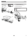
9.4 SHAFT SEAL FIG. 16
i
Check the seals on the PowrMax 605 every
month.
1. Move selector switch (g. 16, 1) to “A” and set delivery
volume controller (2) to „0“.
2. Disconnect mains plug.
3. Loosen the star screws (3) and remove the outlet unit (4).
4. Set delivery volume controller (2) to 1 or 2.
5. Connect mains plug to mains power supply.
6. Move the selector switch (1) to position „F“. As soon as
the stator (5) is released from the rotor (6), set the selector
switch to „A“.
7. Remove the stator (5) completely.
8. Disconnect mains plug.
9. Pull out the two locking pins (7) and remove the anti-twist
lock (8).
10. Remove the ange (9) with a 17-wrench.
11. Remove the container (10).
12. Check the seal (11) and replace if necessary.
13. Clean the shaft seal (12).
14. Check the rotor (6) and replace if necessary (see chapter
9.5).
La page est en cours de chargement...
La page est en cours de chargement...
La page est en cours de chargement...
La page est en cours de chargement...
La page est en cours de chargement...
La page est en cours de chargement...
La page est en cours de chargement...
La page est en cours de chargement...
La page est en cours de chargement...
La page est en cours de chargement...
La page est en cours de chargement...
La page est en cours de chargement...
La page est en cours de chargement...
La page est en cours de chargement...
La page est en cours de chargement...
La page est en cours de chargement...
La page est en cours de chargement...
La page est en cours de chargement...
La page est en cours de chargement...
La page est en cours de chargement...
La page est en cours de chargement...
La page est en cours de chargement...
La page est en cours de chargement...
La page est en cours de chargement...
La page est en cours de chargement...
La page est en cours de chargement...
La page est en cours de chargement...
La page est en cours de chargement...
La page est en cours de chargement...
La page est en cours de chargement...
La page est en cours de chargement...
La page est en cours de chargement...
La page est en cours de chargement...
La page est en cours de chargement...
La page est en cours de chargement...
La page est en cours de chargement...
La page est en cours de chargement...
La page est en cours de chargement...
La page est en cours de chargement...
La page est en cours de chargement...
La page est en cours de chargement...
La page est en cours de chargement...
La page est en cours de chargement...
La page est en cours de chargement...
La page est en cours de chargement...
La page est en cours de chargement...
La page est en cours de chargement...
La page est en cours de chargement...
La page est en cours de chargement...
La page est en cours de chargement...
La page est en cours de chargement...
La page est en cours de chargement...
La page est en cours de chargement...
La page est en cours de chargement...
La page est en cours de chargement...
La page est en cours de chargement...
La page est en cours de chargement...
La page est en cours de chargement...
La page est en cours de chargement...
La page est en cours de chargement...
-
 1
1
-
 2
2
-
 3
3
-
 4
4
-
 5
5
-
 6
6
-
 7
7
-
 8
8
-
 9
9
-
 10
10
-
 11
11
-
 12
12
-
 13
13
-
 14
14
-
 15
15
-
 16
16
-
 17
17
-
 18
18
-
 19
19
-
 20
20
-
 21
21
-
 22
22
-
 23
23
-
 24
24
-
 25
25
-
 26
26
-
 27
27
-
 28
28
-
 29
29
-
 30
30
-
 31
31
-
 32
32
-
 33
33
-
 34
34
-
 35
35
-
 36
36
-
 37
37
-
 38
38
-
 39
39
-
 40
40
-
 41
41
-
 42
42
-
 43
43
-
 44
44
-
 45
45
-
 46
46
-
 47
47
-
 48
48
-
 49
49
-
 50
50
-
 51
51
-
 52
52
-
 53
53
-
 54
54
-
 55
55
-
 56
56
-
 57
57
-
 58
58
-
 59
59
-
 60
60
-
 61
61
-
 62
62
-
 63
63
-
 64
64
-
 65
65
-
 66
66
-
 67
67
-
 68
68
-
 69
69
-
 70
70
-
 71
71
-
 72
72
-
 73
73
-
 74
74
-
 75
75
-
 76
76
-
 77
77
-
 78
78
-
 79
79
-
 80
80


dans d''autres langues
- English: Titan PowrMax 605 User manual
- español: Titan PowrMax 605 Manual de usuario
Documents connexes
Autres documents
-
WAGNER PC 15 Fiche technique
-
 Unitor HPC 30/1 Manuel utilisateur
-
Sharp TE-T56U Le manuel du propriétaire
-
Mitsumi electronic Marine Heating System PQHY-P7296TGMU-A Manuel utilisateur
-
Hilti HTE-P33 Mode d'emploi
-
 Bell Sports Bell Sports, Air Conditioner PQRY-P72-96TGMU-A Manuel utilisateur
-
Bosch GOP40-30C Manuel utilisateur
-
-
Sterling 77311100-0 Guide d'installation
-

