-1 EN-
PCW-1331-US-ASB (19010)
Thank you for purchasing this product.
CAUTION
● Carefullyreadthis
installationmanualtoinstall
thisproductcorrectly.
● Besuretotestoperation
afterinstallationhasbeen
completed.
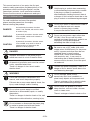
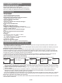
Installation Procedure
1 Mounting the SpaLet Bowl
↓
2 Attaching the Water Shutoff
Valve
↓
3 Mounting the Seat Unit
↓
4 Connecting the Water Supply
Hose <Seat Unit End>
↓
5 Connecting the Water Supply
Hose <Water Shutoff Valve End>
↓
6 Connecting to the Power Supply
↓
7 Positioning and Mounting the
Remote Control
↓
8 Test Operation
↓
9 Mounting the Side Cover
Installation Manual
Advanced Clean 100 SpaLet® Bidet Seat
Model:8017A60GRC
7302385-100 7302385-100EN

-2EN-
This manual consists of two parts; the rst part
contains safety precautions and descriptions of the
procedures when installing the SpaLet, and the
second part contains visual installation methods.
Please use this manual in reference to each part.
SAFETY PRECAUTIONS
For safe installation and use of the product,
please read the precautions thoroughly
before installing the product.
DANGER An imminently hazardous situation
which, if not avoided, will result in death
or serious injury
WARNING A potentially hazardous situation which,
if not avoided, could result in death or
serious injury.
CAUTION
A potentially hazardous situation which,
if not avoided, may result in minor or
moderate injury or damage to the
product or other property.
DANGER
Improper connection of the power plug or
socket can result in a risk of electric shock.
All electrical installation work must be carried
out by a qualied electrician.
There is a danger of short circuit and/or
electric shock.
WARNING
Follow the instructions described in this
manual, and install the product properly.
Failure to do so may cause electric shock, re,
injury, water leakage, and/or ooding.
Do not allow anyone except a certied
electrician to disassemble, repair, or modify
the product.
There is a danger of electric shock or re, and
the product could malfunction, causing injury.
Do not connect or disconnect the power plug
or socket or power cord with wet hands.
There is a danger of electric shock.
Hold the plug or socket when connecting
or disconnecting the power plug or socket.
If the plug or socket is connected or
disconnected by holding the cord, there is
a danger of re or electric shock due to the
plug or socket or cord becoming damaged.
Do not pour water or the cleanser inside or
onto the SpaLet seat unit, remote
control, or power plug or socket.
It may cause electric shock or re.
Do not use any power supply other than
AC120V. Also, do not use any other
method to connect the plug or socket to an
improperly congured receptacle,
exceeding the rated voltage for use.
Be sure to use a VVF cable (with solid
copper wires 20 AWG each) for the power
cord. If a power cord other than the one
specied above is used (such as
strand wires, strand wires attached
with terminals, etc.), it may result in
overheating due to bad connection and
cause corrosion, burnout, re of the prod-
uct and cord.
Connect the power completely. There is a
danger of re or electric shock due to the
cord becoming damaged.
Do not damage, bend, modify,
excessively twist, bind, sandwich, or
place heavy objects on the power cord.
There is a danger of re or electric shock
due to the cord becoming damaged.
Do not install this product in a wet or
damp location, such as inside a shower
room or steam room.
There is a danger of electric shock or re.

-3 EN-
Do not attach the product to any water source
other than potable water.
It may cause electric shock, re and skin
inammation due corrosion of electronic parts
inside the seat unit.
Do not disassemble or modify the product.
It may cause electric shock or re.
Do not use loose outlet.
It may cause electric shock or re.
CAUTION
Install a high-sensitivity, high-speed ground
fault circuit interrupter (with a rated current
value of 15 mA or below) on the primary side
of the power supply.
There is a danger of electric shock.
The SpaLet® bowl is made of ceramics, and
ceramics are fragile. Note the following when
handling the SpaLet bowl:
–– Prior to installation, make sure that the
SpaLet bowl is in a good condition and
not damaged.
–– After installation, check the SpaLet bowl
for any damages.
Failure to do so may cause injury, water
leakage and/or ooding.
Wash out foreign materials or rust inside the
pipes before connecting the product.
Failure to do so could damage the internal
parts of the product, which may cause water
leakage and/or ooding.
Note the following when using the strainer:
–– Close the water shutoff valve when
removing the strainer.
–– When installing the strainer, tighten it
fully so there is no gap.
–– Check that the O-ring is free from
foreign materials when attaching it.
If foreign materials are attached to the O-ring,
it may cause ooding due to water leakage.
Adjust the water shutoff valve and check for
water leakage after the installation.
It may cause water leakage and/or ooding.
If the water is expected to be frozen,
drain the water out from the product.
Failure to do so may cause re, water
leakage, and/or ooding due to damage
from freezing.
Drain the air from the pipes after any
building construction or renovation, or
when water supply is restored after an
interruption.
If the water supply contains air, it may
cause damage or malfunction to the
product or pipes. There is a danger of
injury or damage to the building or
furniture due to ooding.

-4 EN-
POWER SUPPLY
Installthecordandoutletaccordingtothe
specicationsbelow.
Thepowerdistributionworkshouldbedonebyan
electricalcontractor.
● Use an AC120V power supply with a
consumption rating.
Iftheproductisusedwithotherelectricappliances,
setthecorrespondingnumberofoutlets.
● The wiring should be appropriate for the rated
power consumption.
● Set the outlet within the reach of the cord and
high enough from the floor so that water does
not reach it. The length of the power cord
is 1 m (39-3/8").
Donotconnectthepowerplugtotheoutletuntilthe
installationiscompleted.Thereisdangerofmalfunction
.
WATER SUPPLY
●The SpaLet toilet uses solenoid valves which are
fast acting or quick closing valves. The use of
water hammer arrestors is strongly recommended
for this product. All piping behind the walls
should be properly secured and fastened.
●Only use potable water as the water supply.
Usingadifferentwatersupply(industrialwater,
wellwater,etc.)maycausethedurabilityofthe
electricalandmechanicalcomponentsto
deteriorate,resultinginanaccidentormalfunction.
●The water pressure must be more than
0.175MPa/25 PSI (hydrostatic pressure) and
0.10MPa/14.5 PSI (flow pressure) and 17L/min.
when flowing.
● If the water pressure is higher than
0.75MPa/109 PSI, decompress the pressure
by using a decompression valve.
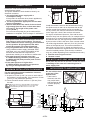
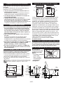
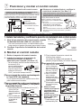
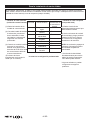
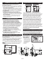
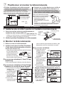
MINIMUM INSTALLATION CLEARANCE
For the required minimum installation clearance,
refertothegurebelow.
* 1Aspaceof70mm(2-3/4")ormoreoneachsideof
theproductisrecommended.Ifitislessthan70mm
(2-3/4"),itmayhindertheoperation.
* 2
Placethewatershutoffvalveto2"(50mm)from
thewall.
*1
70 (2-3/4) min.
*1
70 (2-3/4)
min.
375 (14-3/4) min.
400 (15-3/4) min.
*2
50 (2)
min. 1050 (41-5/16) min.
Remote Control
280
(11)
700 (27-9/16) min.
15 (9/16) min.
Unit: mm
(")
INSTALLATION POSITION OF THE REMOTE CONTROL
a
b b
1300 mm (51-3/16")
On the left side On the right side
Installtheremotecontrolontheleftwallwhenfacing
theSpaLetunit,sothatitisonthesamesideasthe
remotecontrolsignalreceiverasfaraspossible.If,
foranychance,theremotecontrolhastobeinstalled
ontherightside,checkifthereceiverwillreceive
thesignal,beforehand.Moreover,ifthewallissome
distanceawayfromtheSpaLetunit,forexampledueto
alayoutsuchasawashstandbeinginstalledbetween
thewallandtheunit,thesignalmaynotbereceived
bythereceiver.Ifthisisthecase,erectascreenwhich
canreflectsignalswithin1300mm(51-3/16")fromthe
centeroftheSpaLetbowl.Thisscreenshouldbeat
least1100mm(43-5/16")inheightandshouldcover
thedistancebetweenthesignalreceiverandtheremote
control’sinstalledposition.(Notethattheconditions
mayvaryalittledependingonthewallfinishandcolor.)
a Remote control signal receiver
b Remote control
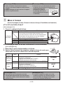
DO NOT PLACE SEAT UNIT ON FLOOR!
Neverplacetheseatunitonthefloor,asthismayresult
in breakage of the seat unit's mounting bolts or
water supply inlet.
NOTES PRIOR TO INSTALLATION
Do not hold the hose
at the rear of the
SpaLet bowl.
* Ifthehoseis
removed,thenthis
maycauseleaks,
andtheSpaLetwill
notflushproperly.
c Hoses
c
Finished
Wall
Remote
Control
Power AC
120V
3-1/4" (82 mm)
2-9/16"
(65 mm)
7-1/16" (180 mm)
Length
39-3/8"
(1000 mm)
Length
16-1/8"
(410 mm)
14-3/4"
(375 mm)
5-15/16"
(150 mm) Drainage Pipe
9-1/16"
(230 mm) 4-3/4" (121 mm)
15-3/16"
(385 mm)
1-3/8"
(35 mm)
16-9/16"
(420 mm)
20-5/8"
(524 mm)
12"
(305 mm)
Meets the Americans with Disabilities Act Guidelines
and ANSI A117.1 Requirements for Accessible and
Usable Building Facilities-Check Local Codes.

-5EN-
FIRMLY FIX THE WATER SUPPLY PIPE
An impact applied to the hose due to high water pressure
may cause vibrations.
Fix the water supply pipe rmly so that it does not loosen.
There is a danger vibration or ooding.
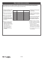
TECHNICAL DATA
Rated voltage
AC120V 50/60Hz
Rated power consumption
850 W (environment 68°F, water 59°F)
Max rated power consumption
1300 W (environment 68°F, water 59°F)
Length of the power cord
39-3/8" (1000 mm)
Length of the water supply hose
16-1/8" (410 mm)
Waterproof grade
IPX4
Water pressure range
Minimum: 0.175MPa/25 PSI [hydrostatic pressure] and
0.10MPa/14.5 PSI (ow pressure) and 17L/min. when owing.
Maximum: 0.75MPa/109 PSI
Water connection cross section
R1/2
Operating temperature range
30°F - 104°F
Units
V = volt, Hz = hertz, W = watt, m = meter,
MPa =mega pascal, in = inch,
°C = degrees Celsius, °F = degrees Fahrenheit,
PSI = pounds square inch
L = Liter, min. = minute
Flushing water volume
S-trap: full 1.32 gallons, light 0.90 gallons
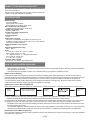
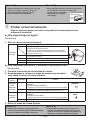
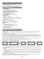
HOW TO CHECK WATER PRESSURE
•Wheninstallingaushtoilet,checkthattherequiredwaterpressures(hydrostaticpressureandowpressure)speciedfor
eachappliancearesecured.
•Ifthewaterpressureexceeds0.75MPa,useapressurereducingvalvebeforeinstallationforuse.
[Water Pressure Checks]
Hydrostaticpressureandowpressurechecksarerequiredforinstallingwatersupplyappliances.Ifnowatershutoffvalvesor
pressuremeasuringdevicesarepreparedbeforehand,connecttheappliancesasshownbelowtomeasurethehydrostaticpressure
andowpressure.Byusingapressuremeasuringdevice,itwillbeeasytochecktheinstallationavailabilityoftheappliance.
Theowpressuregreatlyvaries,dependingontheperipheralconditionsincludingpiping.Besuretomakewaterpressure
measurementwiththewatersupplypipewheretheapplianceisinstalled.
[Hydrostatic Pressure Measuring Method]
Makewaterpressure(hydrostaticpressure)measurementinastatewherevalve1isfullyopenedandvalve2isfullyclosed.
[Flow Pressure Measuring Method]
(1)First,checkthatvalve2isfullyclosedandvalve1isfullyopened.Next,graduallyopenvalve2.Thenthehydrostatic
pressurewillgraduallydecrease(theowpressureisthewaterpressureatthetimeofwatersupply).
(2)Adjustvalve2sothatthewaterpressurewillsettotheminimumrequiredwaterpressureoftheproduct.Thenclosevalve1.
(3)Emptythebucket.Thenfullyopenvalve1andmeasurethetimeuntilthewaterlevelreachesthescaleofthebucket.
Calculatetheowratefromthebucketcapacitydividedbytheperiodoftimeandcheckthattheowratenecessaryforthe
useoftheproductissecured.
•
Iftheinstalledapplianceisusedsimultaneouslywiththewatersupplyapplianceinthekitchen,washroom,etc.,theowpressure
andtheowratewilldecrease.Inthatcase,measuretheowpressureinasimultaneousoperatingstateoftheappliances.
[Dedicated Pressure Measuring Device]
Useapressuremeasuringdevicetomakehydrostaticpressureandowpressurechecks.Itwillbeeasytochecktheinstallation
availabilityoftheappliance.
Water
Supply
Valve 1 for discharging
and shutting off water
Bucket with
scale
Pressure
Gauge

-6EN-
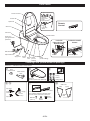
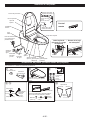
Parts names
Checking Parts (check inside the package)
Numbersin□indicatethestepsintheprocedure.
Seatunit
(product,SpaLetseat,SpaLetlid)
Watershutoff
valve
Ring
shapedcover
Wood
screws
Plastic
anchors
Remotecontrol
Batteries
(AAAx2)
Holder
* Theholderisattachedtotherearofthe
remotecontrol.Slideitofftoremoveit.
Hexagonalnut
Spring
washer
Washer
Tool
Watersupply
hose
410mm
(16-1/8")
Clip(gray)
(OntheSpaLetbody
connectionside)
Clip(white)
(left) (right)
Sidecover
Attached
panel
Upperbodysensor
Remote
Control
Seatunit
Sidecover
Flushbutton
Remotecontrol
receiver
SpaLetbodyindicator
Powerplug
(withgroundfault
protected)
Watershutoffvalve
Open/closeknob
Water
supplyhose
Points of caution
Nozzleshutter
Product No.
Nozzle
(forrearwashing)
SpaLet
seat
Lowerbody
sensor
Nozzle
(for front
washing)
SpaLet
bowl
SpaLetlid
Strainer Deodorizinglter
Left side
(when facing the
SpaLet body)
Inside the nozzle
shutter
2 3
94 5 7
3

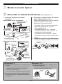
-7EN-
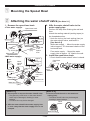
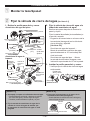
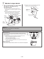
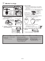
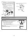
1 Mounting the SpaLet Bowl
Installation Procedure
1. Remove the open/close knob
<Floor water supply>
Wall
Watershutoffvalve
Water
shutoff
valve
Open/closeknob
Approx.
10°
Metaltoolsetting
(Hex)
Watersupplyinlet
100mm
(3-15/16")280mm
(11")
Centerline
ofthe
SpaLet
bowl
Watersupplypipe
Sealingtape
<Wall water supply>
Approx.
10°
Floor
Open/closeknob
Metaltoolsetting
(Hex)
Watersupplyinlet
150mm
(5-15/16")
280mm
(11")
Centerline
ofthetoilet
bowl
Water
supply
pipe
Sealingtape
2. Afxthewatershutoffvalvetothe
water supply pipe.
Performthisstepafternishingthewalland
oor.
Attachthesealingmaterial(sealingtapes)to
thethreadedsection.
* Hookthetoolonthehooksetting(hex)on
thewatershutoffvalve,andfastenit.
[See Note 2-2]
Wallwatersupply···Mountthewatersupply
inletatapprox.10°downwardrelativetothe
horizontallevel.
Floorwatersupply···Mountthewater
supplyinletatapprox.10°tiltedtothewall.
3. Install the open/close knob
* Checkthatthewatershutoffvalveisclosed.
Click
Open/close
knob
Positioning
groove
2 Attaching the water shutoff valve [See Note 2-1]
[Note 2-1]
●Do not push or step on the water shutoff valve.
* Thepipemaycomeloose,orthewatershutoff
valvemaybedamaged,resultinginwater
leakage.
* Thewalloroormayalsobedamaged.
● Afxthewatershutoffvalvewatersupplyinlet
in such a way that the water supply hose is not
crimped.
[Note 2-2]
●Ensure to hook the tool on the metal tool
setting(hex).
* Thewatershutoffvalvemaybedamaged,
resultinginwaterleakage.
Metaltoolsetting
Resin

-8EN-
Washers(x2)
Springwasher
Hexagonalnut
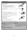
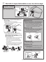
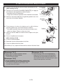
Installation diagram
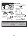
1. Remove the protective cap and tape.
[See Note 3-1]
Plate
(Metal)
Protectivetape
Protectivecap
<SpaLet bowl>
<Rear of seat unit>
2. Set the seat unit on
the SpaLet bowl.
[See Note 3-2]
3. Afxtheseatunit.
①Placethewashers(two)andspringwasher
overeachxingbolt,andafxthenut.
②Fastenthenutbyhand.[See Note 3-3]
Securingbolt
Washers
(x2)
Springwasher
Hexagonalnut
③AlignthetipoftheSpaLetlidtothetipof
theSpaLetbowl.
Theedgeof
theSpaLet
bowlisseen.
④ Tightenthenutwiththeincludedtool.
(Torqueat2.0-2.5N•m
{20-25kgf•cm/1.48ft-lbto1.9ft-lb})
4. Remove the protective sheet
from the SpaLet seat.
SpaLetseatprotectivesheet
Seatunit
Alignthe
securingboltsto
theboltholes.
Turn
3 Mounting the Seat Unit
[Note 3-1]
●Do not remove the plate (metal
item).
* Waterleakagemayresult.
[Note 3-2]
●
Checkthatthisproductisrmly
afxedtotheSpaLetbowl.
●Check that there is no debris
on the SpaLet bowl or seat unit
washing water inlet.
* Waterleakagemayresult.
[Note 3-3]
●Tighten the left and right
hexagonnutsalternatively
in order to ensure even
tightening.
* Waterleakagemayresult.

-9 EN-
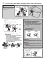
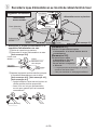
1. Install the water supply hose to the
seat unit.
①Removetheprotectivecap.
②Connectthewatersupplyhose.
[See Note 4-1]
①
②
③Bendthecliptormlyxthewatersupply
hosetotheseatunitwatersupplyinlet.
[See Note 4-2], [See Note 4-3],
[See Note 4-1]
• Afterafxing,rotatetheclip,andcheck
thatitisattachedproperly.
• Also,pullthewatersupplyhosegentlyto
ensurethatitisconnectedproperly.
• Theclipcanonlybeattachedinthe
specieddirectionasshowninthegure
below.[See Note 4-4]
Click
Clip(gray)
[Note 4-1]
●Remove the cap on the water supply hose
water shutoff valve immediately prior to
attaching the water shutoff valve.
* Duringinstallation,debrismayenterthewater
supplyhose,resultinginavalvemalfunction.
[Note 4-2]
●Take care that the O-ring is not damaged.
* IftheO-ringisbrokenorotherwisedamaged,
waterleakagemayoccur.
● Attachthecliprmly.
WrongCorrect
[Note 4-3]
●
Seatthecliprmlyuntilitmakesanaudibleclick.
* Waterleakagemayresult.
[Note 4-4]
●Install the clip horizontally to the side of the
SpaLet body.
* Ifpushedonwithanangle,thentheclipcannot
bebenttoafxitproperly.
4 Connecting the Water Supply Hose <Seat Unit End>
Installation diagram
Watersupplyhose
Clip
(Gray)
Donotapplyexcessiveforce
when connecting the water
supply hose.
Protectivecap
Seatunitwater
supplyinlet
O-ring
[Reference 4-1]
●
Push the clip downward to remove the clip.
Standardscrewdriver
Clip
①
Holdtheclip
withafinger
②
Pushdownward
Clip cross-section view

-10 EN-
5
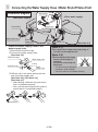
Connecting the Water Supply Hose <Water Shutoff Valve End>
1. Install the water supply hose to the
water supply inlet.
①Removetheprotectivecap.
②Connectthewatersupplyhose.
[See Note 5-2]
②
①
Water
supplyhose
O-ring
Watersupplyinlet
Watershutoffvalve
Protectivecap
③Afxtheclipinthesamewayaswiththe
seatunitwatersupplyinlet.
[See Note 4-2], [See Note 4-3],
[See Note 4-1]
• Afterafxing,rotatetheclip,andcheck
thatitisattachedproperly.
• Also,pullthewatersupplyhosegentlyto
ensurethatitisconnectedproperly.
Click
Clip(white)
[Note 5-1]
●Be careful not to impact the power plug, or
let it fall into the SpaLet bowl.
[Note 5-2]
●
Ensure that the water supply
hose is not bent tightly or
stretched.
Do not use a hose that has
been bent.
* Thehosemaybedamaged
resultinginwaterleakage.
* Thismayresultinincompletecleaning.
Installation diagram
Water
shutoffvalve
Water
supplyhose Water
supplyhose
O-ring
Watershutoffvalve
Water
shutoff
valve
Clip(white)
Clip(white)
Clip(white)
<Wall water supply> <Floor water supply>
[See Note 5-1]

-11 EN-
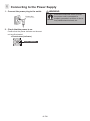
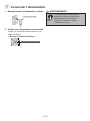
1. Connect the power plug to the outlet.
Powerplug
2. Check that the power is on.
Conrmthatthepowerindicatorontheseat
unitareilluminated.
●Flush button (indicator)
Power indicator
WARNING
Ensuretheelectricaloutlettowhich
thepowercordisconnectedis
properlygrounded,asfailuretodoso
maycauseelectricshock,etc.
GROUND
6 Connecting to the Power Supply

-12EN-
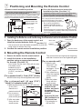
7 Positioning and Mounting the Remote Control
●Remote control installation position
Install the remote control to a position where
the user can reach and operate it.
Installtheremotecontrolintheareashownas“Suggestedinstallationarea”
inthegurebelow,andensuretoinstalltheremotecontrolonaposition
whereitcanbeoperatedeasilywhiletheuserisseatedontheSpaLetseat.
Unit:mm
(")
900(35-7/16)
600(23-5/8)
800(31-1/2)
1200(49)
1000(39-3/8)
Suggestedinstallationarea
Suggestedinstallationarea
foreasieroperation
●
Sit on the SpaLet seat and ensure the
installation position. [See Note 7-1]
Temporarily install the remote control to the target position,
and sit on the seat unit and press the [STOP] button
(ensure to perform a test operation after installation).
Then,standinfrontoftheSpaLetbowland
pushthe[STOP]buttontoensurethata
beepsoundisgeneratedfromtheseatunit.
• Donotpushthe[REARor
[FRONTWASHING]button:
waterwouldcomeoutfromthe
seatunit.
• Ensurethatthereisenoughspaceabovetheremote
controlinstallationpositiontoalloweasyremovaland
mountoftheremotecontrol.
2. Mounting the Remote Control
Installation Procedure
1.
Remove the holder from the remote control.
2. Install the holder to the installation
position using an appropriate method
for the wall. [See Note 7-2]
* Outof4slots,usetheouter2slots(withAmarks).
Iftheholdercanbe
installedonlywitha
holepitchat100mm
(3-15/16"),usetheinner
2slots.
[For a plywood wall (> 5 mm (3/16") thick)]
Afxtheholderrmlywiththesuppliedwoodscrews.
[For a plywood wall (<5 mm
(3/16")
thick) or a plaster board wall]
①
Makethepilotholeswith6mm(1/4")diameter.
(5mm[3/16"]
diameterfora
plasterboardwall)
②
Useahammerto
insertthesupplied
plasticanchorsgently.
③Afxtheholder
rmlywiththe
woodscrews.
Thewoodscrewsaretightatthebeginning,
andthenloosened
onceandtightenedagain.
[For a concrete wall]
①
Makethepilot
holeswith6mm
(1/4")diameter
andapprox.33mm
(1-5/16")depth.
② Useahammerto
insertthesupplied
plasticanchors
gently.
③ Afxtheholder
rmlywiththe
woodscrews.
3. Align the remote
control to the
holder, and push
downward to
mount the remote
control.
4.
Press the [Hr] and
[Min] buttons to set
the current time.
* Payattentionto
AM and PM.
100 mm
156 mm
Holder
Wood
screws
Plastic
anchors
Φ6mm
(1/4")
Holder
Woodscrews
Plasticanchors
33 mm
(1-5/16")
Φ6mm
(1/4")
Holder
Woodscrews
Holder
Remote
Control
Time setting switch
Hr Min
1.
Installing the Batteries and Confirming the Remote Control Installation Position
1. Open the back cover of the remote control, and
installtheincludedbatteries(AAAx2).[See Note 7-1]
* Useatoolsuchasaat-bladescrewdrivertopushthe
hook(lock)toremovethecover.
2. Conrmtheremotecontrolinstallationposition.
Batteries
Hook(lock)
Remotecontrol
Backcover

-13 EN-
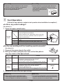
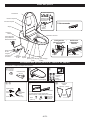
8 Test Operation
(Follow the steps below to conduct a test operation when installation is completed.)
●Isthereanywaterleakage?
[See Note 8-1]
1. Open the water shutoff valve.
Leakage
check
Checked
Details
Isthereanyleak?
* FlushtheSpaLetseveraltimes.
(Waterleakageatthesupply/drainwaterconnecting
sectionsmaynotbeobservedunlesstheSpaLetis
flushedseveraltimes.)
①
②
③
④
□①Betweenthewatershutoffvalveandthewatersupply
hose
□②Betweenthisproductandthewatersupplyhose
□③BetweenthisproductandtheSpaLetbowl
□④BetweentheSpaLetbowlandtheoor
●
Dotherearwashingandfrontwashingoperateproperly?
[See Note 8-2]
1. Connect the power plug to the outlet.
2. Roll up the sleeve and place the arm so that the palm is
over the center of the SpaLet bowl.
Check
item
Checked
Details
Rear
washing
nozzle
□
1.Doesthewarmwaterwithanappropriate
temperaturecomeoutfromthenozzle?
①Pressthe[CLEANSING]button.
②
Ensurethattheshowercomesoutfromthenozzletothepalm.
CLEANSING
□2.
Doestheshowerstopwhenthe[STOP]buttonispressed?
Bidet
nozzle
□
1.Doesthewarmwaterwithanappropriate
temperaturecomeoutfromthenozzle?
①Pressthe[BIDET]button.
②
Ensurethattheshowercomesoutfromthenozzletothepalm.
BIDET
□2.
Doestheshowerstopwhenthe[STOP]buttonispressed?
3. Remove the arm from the SpaLet bowl.
[Note 8-1]
●Water leakage at the supply/drain water
connecting sections may not be observed
unlesstheSpaLetisushedseveraltimes.
[Note 8-2]
●
This product is equipped with a seat sensor that detects
the user. In order for the rear washing and front washing
features to operate, the user must be seated.
[Note 7-1]
●Ensure to install the batteries in the correct
direction (note the negative and positive).
● Donotmixoldandnewbatteries.
●Use the supplied batteries.
[Note 7-2]
●Ensure that there is enough space above the
remote control installation position to allow
easy removal and mount of
the remote control (see the
gurebelow).
Remotecontrolspace
45 mm
(1-3/4")
240 mm (9-7/16")

-14 EN-
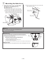
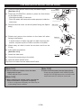
9 Mounting the Side Cover
1. Attach the side covers on both sides.
[See Note 9-1], [See Reference 9-1],
[See Reference 9-2]
①Insertthe“clip”ontheuppersideoftheside
coverintothe“clipholder”ontheSpaLetbowl
②AlignthelinesoftheSpaLetbowlandtheside
cover,andattachthesidecovertothe“Velcro
fastener”onthelowersideoftheSpaLetbowl.
Velcrofastener
Sidecover
Clip
Clip
Clipholder
Clipholder
②
①
③Pushthecenterofthesidecovertosecurethe
“Velcrofastener”rmly.
Velcrofastener
Sidecover
[Reference 9-1]
●If the water shutoff valve is located on the right when facing the
SpaLet, remove the attached panel attached to the right side cover
and attach it to the left side cover.
① Removethescrewonthebackoftherightsidecover.
② Removetheattachedpanelfromtherightsidecover.
*Removeinthedirectionindicated.
③ Attachtheattachedpaneltotheleftsidecover.
*Insertinthedirectionindicated.
④ Insertthescrewonthebackoftheleftsidecovertofastentheattachedpanel.
[Reference 9-2]
●Align the side covers to the SpaLet bowl lines when installing the side covers.
Align the lines
③
Screw
④
②
Sidecover
(R)
Attached
panel
Sidecover
(L)
①
[Note 9-1]
● DonotforcethesidecovertotheSpaLetbowl.
* Thecovermaybedamaged.

-15EN-
(1) Closethewatershutoffvalvetostopthewatersupply.
[See Note 10-1]
(2) Pressthe[FLUSH/FULL]buttonorpresstheflushbutton
ontheSpaLetbody.
* Waitapproximately20seconds.
* Drainthewaterandremovethewaterpressureinsidethe
toiletbody.
(3) Removethesidecoverontheleft(whenfacingtheSpaLet
body).
(4) Rotateandremovethestraineronthelowerleftwhen
facingtotheSpaLet.
* Asmallamountofwatermayspilloutwhenremovingthe
strainer,soplaceapieceofclothorsimilarontheoor.
(5) Washawayalldebrisinsidethestrainerandfromthe
O-ring.
(6) Fullytightenthestrainer.
[See Note 10-2]
(7) Attachthesidecover.
(8) Connectthepowerplugtotheoutlet.
(9) Openthewatershutoffvalve.
(10)Checkforleaksfromthewatershutoffvalve.
Ifthewaterdoesnotowwell,cleanthestrainer.
[Note 10-1]
●Do not remove the strainer when the water
supply valve is open.
* Waterwillleakfromthestrainer.
[Note 10-2]
●When installing the strainer, make sure that the
water shutoff valve is tightened completely.
* Ifthisisnottightenedcompletely,thentheremaybe
waterleakagefromthestrainer.
[Note 10-3]
●How to drain the water from the SpaLet body
* Pressboththe[POWERSAVEON/OFF]button
and[AUTOCLEAN]buttonontheremotecontrol
atthesametimeformorethan2seconds.
O-ring
Strainer
Sidecover
Strainer ②
①
Open/close
knob
Water
shutoffvalve
Close

-16EN-
1. Changing emitting signal
(remote control unit)
(1)Removethebatteriesfrom
theremotecontrolunit.
(2)Refertothesignaltable
ontheright,holddown
thedesiredbutton,insert
thebatteriesandwaitfor
sixsecondswiththebutton
helddown.
(3)Whentheemittingsignal
hasbeenchanged,the
batterymarkonthelower
rightoftheremotecontrol
unitLCDashes.
(Thenumberofashes
differsdependingon
thesignalthathasbeen
changed.)
2.Changing receiving signal
(bidet body)
(1)Removethepowerplugof
thebidetforwhichthesignalis
tobechanged.
(2)Insertthepowerplugagain,
andthenpressthe[STOP]
buttonatleast10timeswithin
10secondsafterinsertion.
NOTE: Do not turn on and off
theindoor(equipment)breaker
toperformtheaboveoperation.
*Ifpoweristurnedon
simultaneouslyformultiple
bidets,thereceivingsignalof
otherbidetsmaybechanged.
*Somesignalscannotbeseton
someproducts.
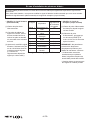
Signal
Number
OperationButton BatteryMark
No.ofFlashes
Signal1 WaterTemp Once
Signal2 SeatTemp Twice
Signal3 Powersave Threetimes
Signal0 NozzleCleaning Fourtimes
Signal4 Hr Fivetimes
Signal5 Min Sixtimes
Signal6 Autoclean Seventimes
Signal7 Dryertemp. Eighttimes
* Signal 0 is the default setting.
Whenmultiplebidetsareinstalled,abidetinotherboothmayalsorespondtothesignalandmalfunction.
Topreventthis,youcanchangethesignalusingtheremotecontrolunityoupurchased.Changeboththe
emittingsignal(remotecontrolunit)andreceivingsignal(bidetbody).
When multiple bidets are installed:

-1 SP-
PCW-1331-US-ASB (19010)
Gracias por comprar este producto.
PRECAUCIÓN
● Leaestemanual
deinstalación
cuidadosamente
parainstalarbienel
producto.
● Verifiqueel
funcionamientouna
vezterminadala
instalación.
Procedimiento de instalación
Montar la taza SpaLet
↓
Fijar la válvula de cierre del agua
↓
Montar la unidad del asiento
↓
Conectar la manguera de
suministro de agua <Extremo
de la unidad del asiento>
↓
Conectar la manguera de
suministro de agua <Extremo
de la válvula de cierre del agua>
↓
Conectar al suministro de
electricidad
↓
Posicionar y montar el control
remoto
↓
Probar el funcionamiento
↓
Montar la tapa lateral
Manual de instalación
Asiento de bidé Advanced Clean 100 SpaLet®
Modelo:8017A60GRC
7302385-100 7302385-100SP

-2SP-
El manual consta de dos partes. La primera parte
contiene las precauciones de seguridad y las
descripciones de los procedimientos para instalar
el SpaLet. La segunda contiene las imágenes de la
instalación. Al usar el manual, consulte ambas partes.
PRECAUCIONES DE SEGURIDAD
Para una instalación y un uso seguros del producto,
lea las precauciones con cuidado antes de instalarlo.
PELIGRO Una situación de peligro inminente que,
de no evitarse, resultará en la muerte o
en una lesión grave.
ADVERTENCIA Una situación de peligro potencial que, de
no evitarse, podría resultar en la muerte o
en una lesión grave.
PRECAUCIÓN
Una situación de peligro potencial que,
de no evitarse, puede resultar en una
lesión menor o moderada o en un daño al
producto u otros bienes.
PELIGRO
La conexión incorrecta del enchufe de
electricidad o la toma puede causar un
choque eléctrico.
Todo el trabajo de instalación eléctrica debe
ser realizado por un electricista calicado.
Existe el peligro de cortocircuito y/o choque
eléctrico.
ADVERTENCIA
Siga las instrucciones del manual e instale el
producto correctamente.
De lo contrario, habrá un riesgo de choque
eléctrico, incendio, lesiones, fuga de agua y/o
inundación.
Únicamente un electricista certicado debe
desarmar, reparar o modicar el producto.
Hay un peligro de choque eléctrico o incendio,
y el producto podría funcionar mal y causar
una lesión.
No conecte ni desconecte el enchufe
de electricidad o la toma o el cable de
electricidad con las manos mojadas.
Hay un peligro de choque eléctrico.
Sostenga el enchufe o la toma al
conectarlos o desconectarlos.
Si el enchufe o la toma se conectan o
desconectan sosteniendo el cable, hay
un peligro de incendio o choque eléctrico
debido a un daño del enchufe, la toma
o el cable.
No vierta agua o limpiador dentro ni sobre la
unidad de asiento SpaLet, el control remoto
ni el enchufe de electricidad o toma.
Puede causar un choque eléctrico o un
incendio.
No use un suministro de electricidad
que no sea AC120V. No use ningún otro
método para conectar el enchufe o la
toma a un receptor con la conguración
incorrecta que exceda el voltaje calicado
para el uso.
Use un cable VVF (con alambre de cobre
sólidos de 20 AWG cada uno) para el
cable de electricidad. Si se usa un cable
de electricidad diferente al especicado
arriba (como alambre trenzado simple
o sujeto a las terminales, etc.), puede
resultar en sobrecalentamiento por la mala
conexión y causar corrosión, desgaste,
incendio del producto y el cable.
Conecte la electricidad por completo. Hay
un peligro de incendio o choque eléctrico
debido a un daño del cable.
No dañe, doble, modique ni gire en
exceso, amarre, intercale ni coloque
objetos pesados sobre el cable de
electricidad.
Hay un peligro de incendio o choque
eléctrico debido a un daño del cable.
No instale el producto en un lugar mojado
o húmedo, como dentro de un cuarto de
ducha o de vapor.
Hay un peligro de choque eléctrico o
incendio.

-3 SP-
No conecte el producto a ninguna fuente de
agua que no sea potable.
Puede causar choque eléctrico, un incendio e
inamación de la piel debido a la corrosión de
las partes electrónicas dentro de la unidad de
asiento.
No desarme ni modique el producto.
Puede causar un choque eléctrico o un
incendio.
No use una toma oja.
Puede causar un choque eléctrico o un
incendio.
PRECAUCIÓN
Instale un interruptor de circuito con pérdida
a tierra de alta velocidad (con un valor de
corriente calicado de 15 mA o menos) en el
lado primario del suministro de electricidad.
Hay un peligro de choque eléctrico.
La taza SpaLet® está fabricada de cerámica,
y la cerámica es frágil. Al manipular la taza
SpaLet, tenga en cuenta lo siguiente:
–– Antes de la instalación, verique que la
taza SpaLet esté en buenas condiciones y
no esté dañada.
–– Después de la instalación, verique que la
taza SpaLet no tenga daños.
De lo contrario, habrá un riesgo de lesiones,
fuga de agua y/o inundación.
Limpie con agua para eliminar todos los
materiales extraños y el óxido dentro de las
tuberías antes de conectar el producto.
De lo contrario, podrán dañarse las piezas
internas del producto y causar fuga de agua
y/o inundación.
Al usar el colador, tenga en cuenta lo
siguiente:
–– Cierre la válvula de cierre del agua
cuando retire el colador.
–– Cuando instale el colador, ajústelo por
completo para que no haya una brecha.
–– Verique que el anillo O no tenga
materiales extraños cuando lo sujete.
Si el anillo O tiene materiales extraños, puede
causar inundación por fuga de agua.
Ajuste la válvula de cierre del agua y verique
que no haya fugas de agua después de la
instalación.
Puede causar fuga de agua y/o inundación.
Si se espera que se congele el agua,
drene el agua del producto.
De lo contrario, habrá un riesgo de
incendio, fuga de agua y/o inundación
debido al daño por el congelamiento.
Drene el agua de las tuberías después
de cualquier construcción o renovación, o
cuando el suministro de agua se restaura
después de un corte.
Si el suministro de agua tiene aire, puede
causar daños o un mal funcionamiento del
producto o las tuberías. Hay un peligro de
lesiones o daño al edicio o a los muebles
por una inundación.

-4 SP-
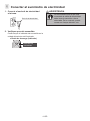
SUMINISTRO DE ELECTRICIDAD
Instaleelcableylatomasegúnlasespecicaciones
másabajo.
Eltrabajodedistribucióndelaelectricidaddebeser
realizadoporuncontratistaelectricista.
● Use un suministro de electricidad AC120V con
calificación de consumo.
Sielproductoseusaconotrosaparatoseléctricos,
configureelnúmerocorrespondientedetomas.
● El cableado debe ser adecuado al consumo de
electricidadcalicado.
● Coloque la toma al alcance del cable y lo
suficientemente alta como para que no llegue el agua.
El largo del cable de electricidad es 1 m (39-3/8").
Noconecteelenchufedeelectricidadalatomahasta
completarlainstalación.Puedefuncionarmal.
SUMINISTRO DE AGUA
●El inodoro SpaLet usa válvulas solenoides que son
de acción rápida o cierre rápido. Se recomienda
encarecidamente el uso de arrestadores de golpe
de ariete para este producto. Todas las tuberías
ubicadas detrás de las paredes deben sujetarse y
fijarse adecuadamente.
●Use únicamente agua potable como suministro
de agua.
Elusodeunsuministrodeaguadistinto(agua
industrialodepozo,etc.)puededeteriorarla
durabilidaddeloscomponenteseléctricosymecánicos
yresultarenunaccidenteomalfuncionamiento.
●La presión de agua debe ser superior a 175MPa/25
PSI (presión hidrostática) y 0.10MPa/14.5 PSI
(presión de flujo) y 17l/min. cuando fluye.
● Si la presión de agua es superior a 0.75MPa/109
PSI, descomprima la presión usando una válvula
de descompresión.
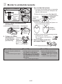
ESPACIO MÍNIMO PARA LA INSTALACIÓN
Consultelaguraacontinuaciónparaconocerel
espacio mínimo requerido para la instalación.
* 1Serecomiendadejarunespaciode70mm(2-3/4")
omásdecadaladodelproducto.Siesinferiora70
mm(2-3/4"),puededicultarelfuncionamiento.
* 2Coloquelaválvuladecierredelaguaa2"(50mm)
delapared.
*1
70 (2-3/4) min.
*1
70 (2-3/4)
min.
375 (14-3/4) min.
400 (15-3/4) min.
*2
50 (2)
min. 1050 (41-5/16) min.
Remote Control
280
(11)
700 (27-9/16) min.
15 (9/16) min.
Unit: mm
(")
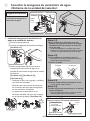
POSICIÓN DE INSTALACIÓN DEL CONTROL
REMOTO
a
b b
1300 mm (51-3/16")
On the left side On the right side
Instaleelcontrolremotoenlaparedizquierdamirando
launidadSpaLet,paraqueestédelmismoladoque
elreceptordelaseñaldecontrolremotolomáslejos
posible.Si,porcualquiercasualidad,elcontrolremoto
debeinstalarsedelladoderecho,verifiqueantessi
elreceptorrecibelaseñal.Además,silaparedestá
alejadadelaunidadSpaLet,porejemplo,debidoauna
disposicióncomounaconsolainstaladaentrelaparedy
launidad,esposiblequeelreceptornorecibalaseñal.
Enesecaso,levanteunapantallaquereflejelasseñales
dentrodelos1300mm(51-3/16")delcentrodelataza
SpaLet.Estapantalladebemedirporlomenos1100
mm(43-5/16")dealturaydebecubrirladistanciaentre
elreceptordeseñalylaposicióndelcontrolremotouna
vezinstalado.(Lascondicionespuedenvariarunpoco
segúnelacabadoyelcolordelapared.)
a Receptor de la señal de control remoto
b Control remoto
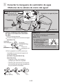
¡NO COLOQUE LA UNIDAD DEL ASIENTO EN EL PISO!
Nocoloquenuncalaunidaddeasientoenelpiso,yaque
puedenromperse los pernos de montaje de la unidad
del asiento o la entrada del suministro de agua.
NOTAS PARA ANTES DE LA INSTALACIÓN
No sostenga la
manguera en la parte
posterior de la taza
SpaLet.
* Siseretiralamanguera,
puede causar
fugas,yelSpaLet
nosedescargará
correctamente.
c Mangueras
c
Finished
Wall
Remote
Control
Power AC
120V
3-1/4" (82 mm)
2-9/16"
(65 mm)
7-1/16" (180 mm)
Length
39-3/8"
(1000 mm)
Length
16-1/8"
(410 mm)
14-3/4"
(375 mm)
5-15/16"
(150 mm) Drainage Pipe
9-1/16"
(230 mm) 4-3/4" (121 mm)
15-3/16"
(385 mm)
1-3/8"
(35 mm)
16-9/16"
(420 mm)
20-5/8"
(524 mm)
12"
(305 mm)
Cumple con las directrices de la Ley de Estadounidenses Dis-
capacitados y ANSI A117.1 Requisitos para las Instalaciones
Accesibles y Utilizables. Verifique los códigos locales.
15 (9/16) mín.
*1
70 (2-34) mín.
375 (14-3/4) mín.
400 (15-3/4) mín.
Control remoto
1050 (41-5/16) mín.
*1
70 (2-34) mín.
280
(11)
*2
50 (2)
mín.
700 (27-9/16) mín.
Control
remoto
Pared
terminada
Electricidad
AC 120 V
Largo 39-3/8”
(1000 mm)
Largo 16-1/8”
(410 mm)
Unidad:
mm (“) 3-1/4” (82 mm)
7-1/16” (180 mm)
14-3/4”
(375 mm)
2-9/16”
(65 mm)
20-5/8”
(524 mm)
5-15/16”
(150 mm)
9-1/16”
(230 mm) 12”
(305 mm)
4-3/4” (121 mm)
Tubería de desagüe
1-3/8”
(35 mm)
15-3/16”
(385 mm)
16-9/16”
(420 mm)
Del lado izquierdo Del lado derecho
1300 mm (51-3/16”)
La page est en cours de chargement...
La page est en cours de chargement...
La page est en cours de chargement...
La page est en cours de chargement...
La page est en cours de chargement...
La page est en cours de chargement...
La page est en cours de chargement...
La page est en cours de chargement...
La page est en cours de chargement...
La page est en cours de chargement...
La page est en cours de chargement...
La page est en cours de chargement...
La page est en cours de chargement...
La page est en cours de chargement...
La page est en cours de chargement...
La page est en cours de chargement...
La page est en cours de chargement...
La page est en cours de chargement...
La page est en cours de chargement...
La page est en cours de chargement...
La page est en cours de chargement...
La page est en cours de chargement...
La page est en cours de chargement...
La page est en cours de chargement...
La page est en cours de chargement...
La page est en cours de chargement...
La page est en cours de chargement...
La page est en cours de chargement...
-
 1
1
-
 2
2
-
 3
3
-
 4
4
-
 5
5
-
 6
6
-
 7
7
-
 8
8
-
 9
9
-
 10
10
-
 11
11
-
 12
12
-
 13
13
-
 14
14
-
 15
15
-
 16
16
-
 17
17
-
 18
18
-
 19
19
-
 20
20
-
 21
21
-
 22
22
-
 23
23
-
 24
24
-
 25
25
-
 26
26
-
 27
27
-
 28
28
-
 29
29
-
 30
30
-
 31
31
-
 32
32
-
 33
33
-
 34
34
-
 35
35
-
 36
36
-
 37
37
-
 38
38
-
 39
39
-
 40
40
-
 41
41
-
 42
42
-
 43
43
-
 44
44
-
 45
45
-
 46
46
-
 47
47
-
 48
48