Smithco Spray Star 1200 Le manuel du propriétaire
- Catégorie
- Accessoires pour véhicules automobiles
- Taper
- Le manuel du propriétaire

Spray Star 1200
Truck Model 20-500-C
Manual System 1201
TeeJet Radion® 8140 1202
TeeJet® 744 1204
TeeJet Aeros/DynaJet® 1215/1218/1220
TeeJet Radion/DynaJet® 1207/1208
SN: 12176
Product Support: Hwy SS & Poplar Ave; Cameron WI 54822
1-800-891-9435 productsupport@smithco.com
Parts & Service

Introduction Service Diagrams Parts Accessories Reference
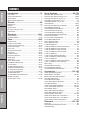
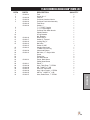
CONTENTS
Introduction ............................................1-3
Introduction ........................................................................ 1
General Safe Practices...................................................... 2
................................................................... 3
Optional Spray Equipment................................................. 3
Service ....................................................4-9
Maintenance ................................................................... 4-6
Storage .............................................................................. 6
Service Chart ..................................................................... 7
End User’s Service Chart .................................................. 8
Adjustments ....................................................................... 9
Diagrams ............................................10-13
Wiring Diagram ........................................................... 10-11
Hydraulic Diagram ...................................................... 12-13
Parts....................................................14-59
Body & Frame ............................................................14-15
Engine Cover/ Roll Bat ...............................................16-17
Control Panel and Steering ........................................18-19
Foot Pedal Linkage.....................................................20-21
Front Axle .................................................................22-23
Oil Tank and Fuel Tank ...............................................24-25
Seat Panel .................................................................. 26-27
Hydraulic Pump ..........................................................28-29
Engine and Exhaust ...................................................30-31
Spray Pump ................................................................32-33
Spray Tank ..................................................................34-35
Turbo Quad Agitator ..................................................36-37
Park Brake and Rear Axle ..........................................38-39
15-301 Orbital ............................................................40-41
76-638 Hydrostatic Pump ........................................... 42-43
76-638 Pump Maintenance ........................................44-54
76-197 Eaton Gear Pump................................................ 55
76-197 Pump Maintenace ..........................................56-57
76-238 Wheel Motor ........................................................ 58
76-238-Wheel Motor Maintenance .............................59-80
20-684 Flow meter........................................................... 81
15-970 Hypro® Pump .................................................82-83
Spray Systems .................................84-134
Plumbing 1201 Manual System ..................................84-85
Plumbing 1202 System (Radion® 8140) ....................... 86-89
Plumbing 1204 System (TeeJet® 744) ........................90-93
1202 Wiring System(Radion® 8140) .................................. 94
1204 Wiring System (TeeJet® 744) ................................ 95
Control Mounts ...........................................................96-97
Plumbing 1207/1208/1215/1218/1220 .......................98-99
1207/1208 DynaJet Wiring ............................................ 100
1207/1208 Rear Module Mounts ................................... 101
1215/1218/1220 Aeros Wiring ....................................... 102
1215/1218/1220 DynaJet Wiring ................................... 103
1215/1218/1220 Rear Module Mounts .......................... 104
14-801/14-607 Strainer.................................................. 105
15-737/14-628 Flanged Strainer.................................... 106
15-743 Manifold Ball Valve ............................................ 107
20-817 Regulaotr Valve ................................................. 108
20-785 Regulator Valve ................................................. 109
17-580 20’ HD Boom .............................................. 110-113
17-580 20’ HD Boom 1202/1204 Plumbing ................... 114
17-580 20’ HD Boom 1207 Plumbing ............................ 115
17-580 20’ HD Boom 1220 Plumbing ............................ 116
17-585 18’ HD Boom 1218 Plumbing ............................ 117
17-585 18’ HD Boom .............................................. 118-121
17-585 18’ HD 1202/1204 Plumbing ............................. 122
17-585 18’ HD Boom 1208 Plumbing ............................ 123
17-601 15’ HD Boom .............................................. 124-127
17-601 15’ HD Boom 1202/1204 Plumbing ................... 128
17-601 15’ HD Boom 1215 Plumbing ............................ 129
Boom Hinge ................................................................... 130
Standard Nozzle Assembly............................................ 131
1207/1208 Nozzle Assembly ..................................132-133
1215/1218/1220 Nozzle Assembly ................................ 134
Accessories ...................................135-160
15-835 Tank Rinsing System ......................................... 135
16-906 Electric Hose Reel .....................................136-137
Electric Hose Reel Wiring Diagram ............................... 138
Hose Reel Adjustments ................................................. 139
16-129 Manual Hose Reel ............................................ 140
15-967 Hose Reel for HD Booms ................................. 141
Hose Reel Plumbing ...............................................142-143
15-965 Foam Marker Installation ............................144-147
14-291 Foam Marker Parts List .............................. 148-149
Foam Marker Wiring ...................................................... 150
20-815 Water Meter Kit (Gallons) .................................. 151
20-816 Water Meter Kit (Liters) ..................................... 151
15-968 20 Gallon Rinse Tank ................................. 152-153
30-006 Fresh Water Tank - Rear Mount ........................ 154
10-653 Fresh Water Tank - Front Mount........................ 155
15-619 Chemical Clean-load System ..................... 156-160
Reference .......................................161-162
Decal List ....................................................................... 161
Quick Reference Replacement Parts ............................ 162
Limited Warranty

1
Introduction
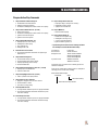
INTRODUCTION
Thank you for purchasing a Smithco product.
Read this manual and all other manuals pertaining to the Spray Star 1200 carefully as they have safety, op-
erating, assembly and maintenance instructions. Failure to do so could result in personal injury or equipment
damage.
Keep manuals in a safe place after operator and maintenance personnel have read them. Right and left sides
are from the operator’s seat, facing forward.
All Smithco machines have a Serial Number and Model Number. Both numbers are needed when ordering
parts. The serial number plate on the Spray Star 1200 is located on right mainframe behind exhaust. Refer to
engine manual for placement of engine serial number.
www.Smithco.com.
Information needed when ordering replacement parts:
1. Model Number of machine
2. Serial Number of machine
3. Name and Part Number of part
4. Quantity of parts
For easy access record your Serial and Model numbers here.
SMITHCO CUSTOMER SERVICE 1-800-891-9435
WARNING
Failure to follow cautious operating practices can re-
sult in serious injury to the operator or other persons.
The owner must understand these instructions, and
must allow only trained persons who understand these
instructions to operate this vehicle.
WARNING:
Engine exhaust and some of its constituents are
known to the State of California to cause cancer,
birth defects, and other reproductive harm.
For more information visit
www.P65Warning.ca.gov

2
Introduction
SAFE PRACTICES
1. It is your responsibility to read this manual and all publications associated with this machine.
2. Never allow anyone to operate or service the machine or its optional equipment without proper training
and instructions. Never allow minors to operate any equipment.
3. Learn the proper use of the machine, the location and purpose of all the controls and gauges before
you operate the equipment. Working with unfamiliar equipment can lead to accidents.
4. Wear all the necessary protective clothing and personal safety devises to protect your head, eyes, ears,
Beware of overhead obstructions and underground obstacles. Stay alert for hidden hazards.
6. Never operate equipment that is not in perfect working order or without decals, guards, shields, or other
protective devices in place.
7. Never disconnect or bypass any switch.
8. Carbon monoxide in the exhaust fumes can be fatal when inhaled, never operate a machine without
proper ventilation.
10. Keep engine clean. Allow the engine to cool before storing and always remove the ignition key.
11. Disengage all drives and set park brake before starting the engine.
cause serious injury.
13. This machine demands your attention. To prevent loss of control or tipping of the vehicle:
A. Use extra caution in backing up the vehicle. Ensure area is clear.
B. Do not stop or start suddenly on any slope.
C. Reduce speed on slopes and in sharp turns. Use caution when changing directions on slopes.
D. Stay alert for holes in the terrain and other hidden hazards.
14. Before leaving operator’s position:
A. Disengage all drives.
B. Set park brake.
D. If engine has to run to perform any maintenance keep hands, feet, clothing and all other parts of
body away from moving parts.
15. Keep hands, feet and clothing away from moving parts. Wait for all movement to stop before you clean,
adjust or service the machine.
16. Keep the area of operation clear of all bystanders.
17. Never carry passengers.
18. Stop engine before making repairs/adjustments or checking/adding oil to the crankcase.
19. Use parts and materials supplied by Smithco only. Do not modify any function or part.
20. Use caution when booms are down as they extend out beyond the center line of the machine.
These machines are intended for professional maintenance on golf courses, sports turf, and any other
area maintained turf and related trails, paths and lots. No guaranty as to the suitability for any task is
expressed or implied.

3
Introduction
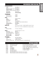
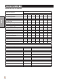
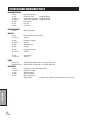
SPECIFICATIONS SPRAY STAR 1200
WEIGHTS AND DIMENSIONS
Length 120" (305 cm)
Width 65" (165 cm)
Width With 18' Boom Open 240" (610 cm)
Height w/ Roll Bar 77" (195 cm)
Height w/ 18' Booms Folded 110" (279 cm)
Wheel Base 68" (173 cm)
Weight Empty 1877 lbs (851 kg)
Weight Full 3626 lbs (1645 kg)
SOUND LEVEL (DBA)
At ear level 92 dBA
At 3 ft. (0.914 m) 98 dBA
At 30 ft. (9.14 m) 88 dBA
ENGINE
Make Briggs & Stratton
Model# 613477
Type / Spec# 0271-J1
Horsepower 35 hp (26 kW)
Fuel Unleaded 87 Octane Gasoline Minimum
Cooling System Air Cooled
Lubrication System Full Pressure
Alternator 20 Amp
WHEELS & TIRE Front: Two 20 x 10.00 x 10 NHS Multi-Rib; 20 psi (1.4 bar)
Rear: Two 24 x 13.00 x 12 NHS Multi-Trac; 20 psi (1.4 bar)
SPEED
BATTERY Automotive type 24F - 12 volt
BCI Group Size 24
Cold Cranking Amps 900 minimum
Ground Terminal Polarity Negative (-)
Maximum Length 10.25" (26 cm)
Maximum Width 6.88" (17 cm)
Maximum Height 10" (25 cm)
FLUID CAPACITY
Crankcase Oil See Engine Manual
Fuel 10 gallon (45.46 liters)
Hydraulic Fluid 5 gallon (19 liters)
Grade of Hydraulic Fluid SAE 10W-40 API Service SJ or higher Motor Oil
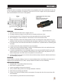
OPTIONAL EQUIPMENT
20-816 Water Meter Kit (Liters) 20-815 Water Meter Kit (Gallons)
15-619 Chemical Clean-load 10-653 Fresh Water Wash Tank- Front Mount
15-622 Canopy 30-006 Fresh Water Wash Tank - Rear Mount
15-965 Foam Marker 15-968 26 Gal. Wash System with Electric Pump
17-601 15' HD Boom 17-585 18' HD Boom
17-580 20' HD Boom 17-622 Boom Shield for 17-585
15-967 Hose Reel Mount Kit 17-590 Sonic Boom
15-835 Tank Rinsing System
16-129 Manual Rewind Hose Reel, 200-foot/61-meter capacity
16-906 Electric Rewind Hose Reel, 200-foot/61-meter capacity

4
Service
MAINTENANCE
Before servicing or making adjustments to machine, stop engine and remove
key from ignition.
Use all procedures and parts prescribed by the manufacturer's. Read the en-
gine manual before operation.
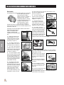
LUBRICATION
Use No. 2 General purpose lithium base grease and lubricate every 100 hours. The Spray Star 1200 has 7
lube points.
A. One on the rod end of hydraulic cylinder.
B. One on each the right and left spindles.
C. One on the reverse pedal.
D. One on each end of tie rod.
E. One on the forward pedal.
ELECTRICAL CONNECTIONS
Use dielectric grease on all electrical connections.
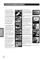
AIR CLEANER ON ENGINE
1. Unclip the two clips, remove the cover and pull out the element.
3. Clean out the inside of the body and cover.
4. Place the element into the body and put the cover back on..
Do not use petroleum solvents, e.g.., kerosene, which will cause cartridge to
deteriorate. Do not use pressurized air to clean cartridge. Pressurized air can
damage cartridge.

5
Service
MAINTENANCE
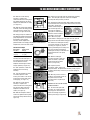
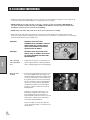
ENGINE OIL
Change and add oil according to chart below based on air temperature at the time of operation. Do not over-
with recommended oils. Do not mix oil with gasoline.
SAE Viscosity Grades
HYDRAULIC OIL
1. Use SAE 10W-30 API Service SJ or higher motor oil.
4. After changing oil, run the machine for a few minutes. Check oil level and for leaks.
5.
-
taminants. Check and service more frequently when operating in extremely cold, hot or dusty conditions.
-
lem exists.
9. In extreme temperatures you can use straight weight oil. We recommend SAE 30W API Service SG
when hot (above 90°F (33°C)) and SAE 10W API Service SJ or higher when cold (below 32°F (0°C)
ambient temperature. Use either motor oil or hydraulic oil, but do not mix.
10. Oil being added to the system must be the same as what is already in the tank.
as to which type you put in.
TIRE PRESSURE
WHEEL MOUNTING PROCEDURE
2. Block wheel on opposite corner.
3. Loosen nuts slightly on wheel to be removed.
4. Jack up machine being careful not to damage underside of machine.
5. Place wheel on hub lining up bolt holes.
hours thereafter.
7. Lower machine to ground and remove blocks and jack.

6
Service
MAINTENANCE
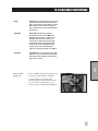
BATTERY
any ignited object to come near the battery. When charging or working near battery, always shield your eyes
and always provide proper ventilation.
Battery cable should be disconnected before using “Fast Charge.”
Charge battery at 15 amps for 10 minutes or 7 amps for 30 minutes. Do not exceed the recommended
charging rate. If electrolyte starts boiling over, decrease charging.
1. Filling batteries in well-ventilated areas.
2. Wear eye protection and rubber gloves.
3. Avoid breathing fumes when electrolyte is added.
4. Avoid spilling or dripping electrolyte.
Battery Electrolyte is an acidic solution and should be handled with care. If
electrolyte is splashed on any part of your body, ush all contact areas imme-
diately with liberal amounts of water. Get medical attention immediately.
Use of booster battery and jumper cables. Particular care should be used
when connecting a booster battery. Use proper polarity in order to prevent
sparks.
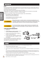
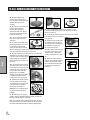
TO JUMP START (NEGATIVE GROUNDED BATTERY):
1. Shield eyes.
2. Connect ends of one cable to positive (+) termi-
3. Connect one end of other cable to negative (-)
terminal of "good" battery (C).
4. Connect other end of cable (D) to engine block
on unit being started (NOT to negative (-) termi-
nal of battery)
To prevent damage to other electrical components on
unit being started, make certain that engine is at idle
speed before disconnecting jumper cables.
STORAGE
If the engine will be out of service for two or more months, use the following storage procedure.
1. Clean the exterior surfaces of the engine.
3. The fuel system must be completely emptied, or the gasoline must be treated with a stabilizer to prevent deteriora-
tion.
If you choose to use a stabilizer, follow manufacturers recommendations, and add the correct amount for the ca-
pacity of fuel system. Fill fuel tank with clean, fresh gasoline. Run engine for 2-3 minutes to get stabilized fuel into
To empty the system, drain fuel tank and carburetor, or run engine until tank and system are empty.
4. Remove the spark plugs. Add one tablespoon of engine oil into each spark plug hole. Install plugs, but do not con-
nect the plug leads. Crank the engine two or three revolutions.
5. Store machine in a clean, dry place.

7
Service
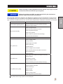
SERVICE CHART
Before servicing or making adjustments to the machine, stop engine, set park
break, block wheels and remove key from ignition.
Follow all procedures and ONLY use parts prescribed by the manufacturer.
Read the engine manual before maintenance.
but as a supplement. You must adhere to the guidelines established by the manufacturer for warranty cover-
age. In adverse conditions such as dirt, mud or extreme temperatures, maintenance should be more frequent.
Maintenance Service Interval Maintenance Procedure
Torque the wheel lug nuts. (64-74 ft/lb (87-100 Nm))
Before each use daily
Check the engine oil level.
Check the tire pressure.
Inspect and clean the machine.
Change Hydraulic Oil Filter.
Every 100 hours
1&2
Clean pre-cleaner.1
Replace spark plug .
Lubricate machine.
Clean or change remote air cleaner.
Service exhaust sytem.
Check belt tension .
Every 250 hours
Check engine valve clearance and adjust if necessary.
Check idle speed.
Clean battery terminals.
Torque the wheel lug nuts. (64-74 ft/lb (87-100 Nm))
Every 500 hours or yearly
1
2
Clean air cooling system.1
1 In dusty conditions or when airborne debris is present, clean more often.
2

8
Service
END USER SERVICE CHART
Duplicate this page for routine use.
Maintenance Check Item For the week of:
Mon Tues. Wed. Thurs. Fri. Sat. Sun.
Check the Safety Seat Switch
Check Steering Operation
Check the fuel level
Check the engine oil level.
Check for unusual engine noises
Check the hydraulic oil level
Check the tire pressure
Check the Instrumentation
Inspect electrical system for frayed wires
Check park brake adjustment
Change oil.
Lubricate Machine
Ensure all warning decals are intact.
Areas of Concern
Inspection Performed by:
Item Date Information

9
Service
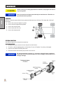
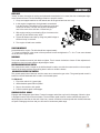
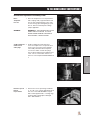
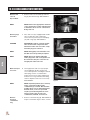
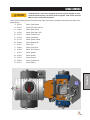
ADJUSTMENTS
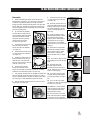
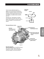
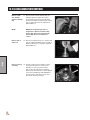
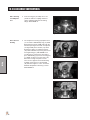
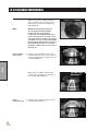
WHEEL CREEP
"Creep" is when the engine is running and hydrostatic transmission is in neutral, but due to inadequate align-
ment, wheels still move. Do the following procedure to stop this motion.
2. In the engine compartment, the hydrostatic transmission
is on the left side. The shift arm (D) is under the pump and
comes out the side. The idler arm (B) has a bearing that
runs in the notch of the shift arm. Loosen bolt (A).
3. With engine running, move bearing (B) so it centers on the
shift arm (D) and 'wheel creep' stops.
4. Tighten all fasteners and test by using foot pedal linkage to
see that 'creep' is removed.
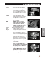
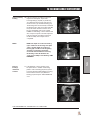
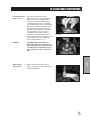
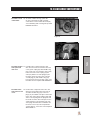
SPRAY PUMP WITH BELT
Located below the engine. The belt should have approximately
1/25/16 -18 x 11/4 set screw located
on the foot of the pump mount.
PARK BRAKE
needed turn clevis on brake cable to adjust length of cable.
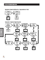
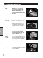
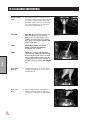
MASTER BOOM SWITCH (FOOT SWITCH)
GROUND SPEED CONTROL (FOOT SWITCH))
The ground speed control does not work the same as an automotive type cruise. The ground speed control is
TO ENGAGE:
1. Flip rocker switch ‘On’ (green light).
2. Obtain desired speed with foot pedal.
3. Step on foot switch to lock speed.
4. Push foot switch again to disengage.
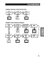
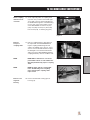
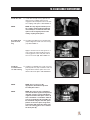
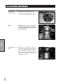
SPRAY BOSS CONTROL - ORANGE
Engages and disengages speed boss. Forward is engage and all the way back is disengage. When the lever
is engaged it sets a stop for the accelerator. The accelerator pedal must be used to maintain this speed. To
adjust speed use the knob on the end of the lever, counter clockwise increases speed and clockwise decreas-
es speed. Disengage the lever and you will have full accelerator pedal range.

10
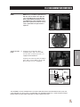
Diagrams
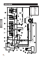
Color Code Chart
Bl Blue
Br Brown
Y Yellow
G Green
O Orange
R Red
B Black
GY Gray
W White
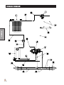
WIRING DIAGRAM

11
Diagrams
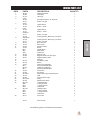
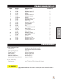
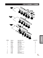
WIRING PARTS LIST
REF# PART# DESCRIPTION QUANTITY
1 30-356 GPS Speedometer 1
2 12-804 Hour Meter 1
3 10-732 LED Light 1
4 Lights
15-727 Rocker - No light 1
5 Cruise
15-726 Lighted Switch 1
15-732 Rocker - Green 1
6 Pump
15-726 Lighted Switch 1
15-731 Rocker - Amber 1
7 Left Boom
15-727 Rocker - No light 1
8 Right Boom
15-727 Rocker - No light 1
9 30-214 Boom Actuator 2
10 15-970 Spray Pump 1
11 33-480 Pressure Switch 1
12 77-207 Buzzer 1
8874 Female Bullet 1
8875 Male Bullet 2
8963 Heat Shrink 2
13 33-084 Magnetic Coil 1
14 76-636 Briggs & Stratton 35 HP Engine 1
15 76-327 Negative Battery Cable 1
16 Solenoid 1
17 75-518 Red Battery Cable 1
18 33-216 Battery 1
19 77-261 40 Amp Circuit Breaker 1
8977 Red Circuit Breaker Boot 1
20-733 10AMP Circuit Breaker 1
8877 Red Circuit Breaker Boot 1
20 14-292 Seat Switch 1
21 13-488 Key Switch 1
22 20-730-01 GPS Antenna (part of speedometer) 1
23 32-576 USB 1
24 50-359 Oil Temperature Light 1
25 30-042-06 Relay 1
26 33-509 Master Boom Switch 1
28 8931-20 10GA White Wire 1
8928 5/16 Ring Terminal 1
8912 3/16 Ring Terminal 1
8963 Heat Shrink 2
29 8919-26 10GA Red Wire 1
8928 5/16 Ring Terminal 1
8912 3/16 Ring Terminal 1
8963 Heat Shrink 2
30 33-271 Fuse Panel 1
15-941 Wire Harness 1
Use dielectric grease on all electrical connections.

12
Diagrams
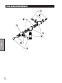
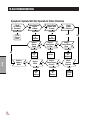
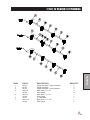
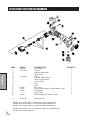
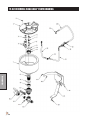
HYDRAULIC DIAGRAM

13
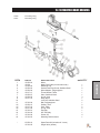
Diagrams
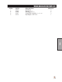
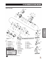
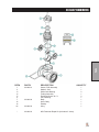
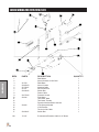
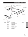
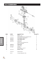
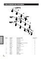
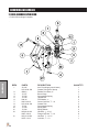
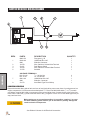
HYDRAULIC DIAGRAM PARTS LIST
REF# PART# DESCRIPTION QUANTITY
1 15-624 Cooler 1
2 15-982 Hydraulic Hose, 35" 1
3 15-946 Hydraulic Hose, 74" 1
4 15-301 Orbital 1
5 10-671 Hydraulic Hose, 65" 2
6 15-839 Hydraulic Cylinder 1
15-839-01 Seal Kit 1
7 15-945 Hydraulic Hose, 76.5" 1
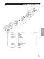
8 76-638 Hydrostatic Pump 1
9 76-197 Gear Pump 1
10 15-682 Hydraulic Hose, 463/4" 2
11 20-656 Tube Assembly 4
12 76-238 Wheel Motor 2
13 34-057 Tee 2
14 8832-29 3/4" Suction Hose x 29" 1
18-040 Hose Clamp 2
15 8832-30 3/4" Suction Hose x 30" 1
18-040 Hose Clamp 2
16 60-473 Hydraulic Oil tank 1
17 8917-16 3/8" Suction Hose x 16" 1
18-040 Hose Clamp 2
18 26-016 Oil Filter 1
23-031 Replacement Filter 1
19 15-948 Hydraulic Hose, 16.5" 1
20 15-981 Hydraulic Hose, 32" 1
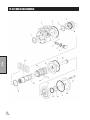
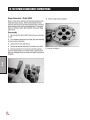
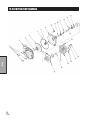
PUMP DISPLACEMENT
76-638 Hydrostatic Pump
Displacement Variable to 1.44 in3/R (23.6 cm3/R)
22.44 gpm (84.94 lpm) at 3600 rpm
Max Operating Speed 3600 rpm
Rated Pressure 3000 psi (206.8 bar)
Max Pressure 5000 psi (344.7 bar)
Max Inlet Vacuum 6 in Hg (.203 bar)
Max Inlet Temperature 225°F (107°C)
Max Allowable Case Pressure 25 psi (1.72 bar)
76-197 Gear Pump
Displacement .40 in3/R (6.6 cm3/R) 6.23 gpm (25.39 lpm)
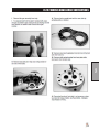
Over tightened ttings will result in crushing the cone which will create a
leak.

14
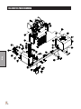
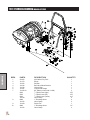
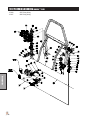
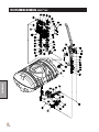
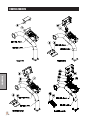
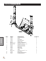
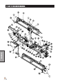
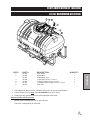
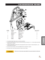
Parts
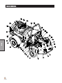
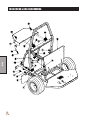
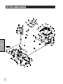
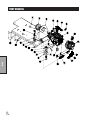
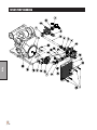
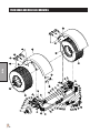
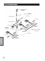
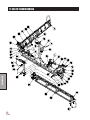
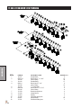
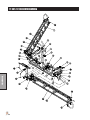
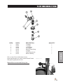
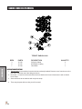
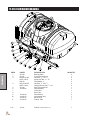
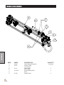
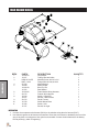
MAIN DRAWING

Parts
15
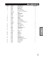
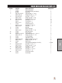
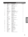
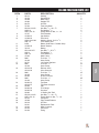
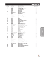
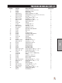
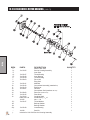
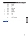
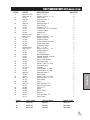
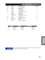
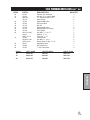
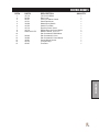
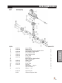
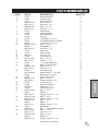
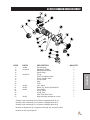
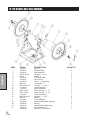
BODY & FRAME PARTS LIST
REF# PART# DESCRIPTION QUANTITY
1 10-678 Reverse Pedal 1
2 10-677 Forward Pedal 1
3 15-925 Main Frame 1
4 10-663 RH Front Fender 1
5 16-857 Front Tire and Wheel 2
16-857-01 Tire, 20 x 10.00 - 10NHS 4 Ply 2
42-161-02 Wheel 2
6 10-683 Side Control Arm 1
10-684 Control Panel 1
7 20-659 Mud Flap 4
8 60-106 Park Brake Handle 1
9 15-781 Drink Cup Holder 1
10 76-198-03 Seat Belt 1
11 15-963 Tailpipe 1
12 15-962 Tailpipe Guard 1
13 20-812 Front Tank Strap 1
14 16-225 Rear TIre and Wheel 2
16-225-01 Tire, 24 x 13.00 - 12NHS 4 Ply 2
16-225-02 Wheel 2
15 10-168 Rear Fender 2
16 20-811 Rear Tank Strap 1
17 17-615 Boom Support Tube 2
18 16-557 Square Cap 2
19 20-802 200 Gallon Spray Tank 1
16-169 Strainer Basket 1
20 15-964 Air Gap Filler 1
21 16-953 Lid 1
16-953-01 Gasket for Lid 1
22 10-639 Lid Stop 1
23 15-922 Roll Bar 1
24 15-936 Engine Hood 1
25 15-934 Back Panel 1
26 14-294 Seat kit 1
10-706 Arm Rests 1
27 10-120 Speed Boss Handle 1
28 20-057 Steering Wheel 1
20-129 Center Steering Wheel Cap 1
29 10-732 LED Head Light 1
30 10-662 LH Front Fender 1
31 10-680 Seat Frame 1
32 10-705 Foot Rest 1

16
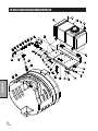
Parts
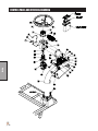
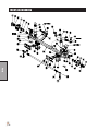
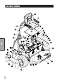
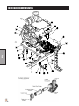
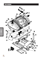
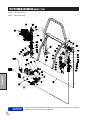
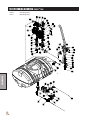
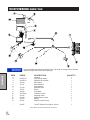
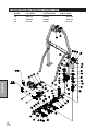
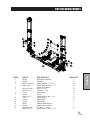
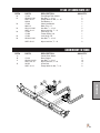
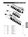
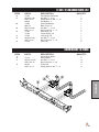
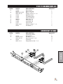
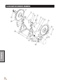
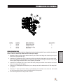
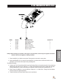
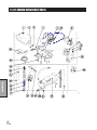
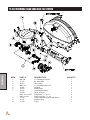
ENGINE HOOD & ROLL BAR DRAWING

Parts
17
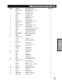
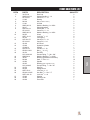
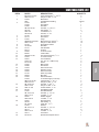
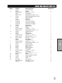
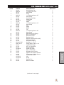
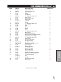
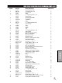
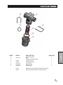
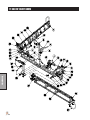
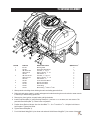
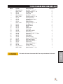
ENGINE HOOD AND ROLL BAR PARTS LIST
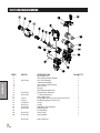
REF# PART# DESCRIPTION QUANTITY
1 15-940 RH Fender Brace 1
15-939 LH Fender Brace (not shown) 1
2 20-659 Mud Flap 2
3 HBC-516-18-100 Carriage Bolt, 5/16 -18 x 1 4
HNFL-516-18 Flange-Loc Nut, 5/16 - 18 4
4 HB-14-20-075 Hex Bolt, 1/4 -20 x 3/4 6
HNFL-14-20 Flange-Loc Nut, 1/4- 20 6
5 HWF-14-150 Fender Washer, 1/4 x 11/2 6
6 HB-12-13-175 Hex Bolt, 1/2 - 13 x 13/4 10
HW-12 Flat Washer, 1/2 10
HNTL-12-13 Lock Nut, 1/2 - 13 10
7 15-935 Seat Belt Bracket 2
HB-12-13-150 Hex Bolt, 1/2 - 13 x 11/2 4
HNTL-12-13 Lock Nut, 1/2 - 13 4
8 15-922 Roll Bar 1
9 15-013 Rubber Bumper 2
HNFL-14-20 Flange-Loc Nut, 1/4 - 20 2
10 15-952 RH Hood Stand 1
11 15-936 Engine Hood 1
12 HSTP-516-18-075 Truss Head Screw, 5/16 -18 x 3/4 4
HNFL-516-18 Flange-Loc Nut, 5/16 - 18 4
13 15-951 LH Hood Stand 1
14 32-695 Adjustable Hinge 2
15 HSM-10-32-063 Machine Screw, 10-32 x 5/8 8
HNFL-10-32 Flange-Loc Nut, 10 - 32 8
16 15-934 Back Panel 1
1/4 Sheet
17 HB-38-16-075 Hex Bolt, 3/8 -16 x 3/4 2
HNFL-38-16 Flange-Loc Nut, 3/8 -16 2
18 hb-38-16-125 Hex Bolt, 3/8 - 16 x 11/4 1
HNTL-38-16 Lock Nut, 3/8 - 16 1
19 HB-38-16-150 Hex Bolt, 3/8 - 16 x 11/2 1
HNTL-38-16 Lock Nut, 3/8 - 16 1
20 15-931 Fuel Pump mount 1
76-471 Fuel Pump 1

18
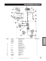
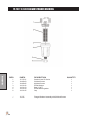
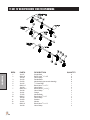
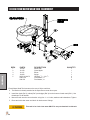
Parts
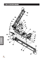
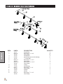
CONTROL PANEL AND STEERING DRAWING
La page est en cours de chargement...
La page est en cours de chargement...
La page est en cours de chargement...
La page est en cours de chargement...
La page est en cours de chargement...
La page est en cours de chargement...
La page est en cours de chargement...
La page est en cours de chargement...
La page est en cours de chargement...
La page est en cours de chargement...
La page est en cours de chargement...
La page est en cours de chargement...
La page est en cours de chargement...
La page est en cours de chargement...
La page est en cours de chargement...
La page est en cours de chargement...
La page est en cours de chargement...
La page est en cours de chargement...
La page est en cours de chargement...
La page est en cours de chargement...
La page est en cours de chargement...
La page est en cours de chargement...
La page est en cours de chargement...
La page est en cours de chargement...
La page est en cours de chargement...
La page est en cours de chargement...
La page est en cours de chargement...
La page est en cours de chargement...
La page est en cours de chargement...
La page est en cours de chargement...
La page est en cours de chargement...
La page est en cours de chargement...
La page est en cours de chargement...
La page est en cours de chargement...
La page est en cours de chargement...
La page est en cours de chargement...
La page est en cours de chargement...
La page est en cours de chargement...
La page est en cours de chargement...
La page est en cours de chargement...
La page est en cours de chargement...
La page est en cours de chargement...
La page est en cours de chargement...
La page est en cours de chargement...
La page est en cours de chargement...
La page est en cours de chargement...
La page est en cours de chargement...
La page est en cours de chargement...
La page est en cours de chargement...
La page est en cours de chargement...
La page est en cours de chargement...
La page est en cours de chargement...
La page est en cours de chargement...
La page est en cours de chargement...
La page est en cours de chargement...
La page est en cours de chargement...
La page est en cours de chargement...
La page est en cours de chargement...
La page est en cours de chargement...
La page est en cours de chargement...
La page est en cours de chargement...
La page est en cours de chargement...
La page est en cours de chargement...
La page est en cours de chargement...
La page est en cours de chargement...
La page est en cours de chargement...
La page est en cours de chargement...
La page est en cours de chargement...
La page est en cours de chargement...
La page est en cours de chargement...
La page est en cours de chargement...
La page est en cours de chargement...
La page est en cours de chargement...
La page est en cours de chargement...
La page est en cours de chargement...
La page est en cours de chargement...
La page est en cours de chargement...
La page est en cours de chargement...
La page est en cours de chargement...
La page est en cours de chargement...
La page est en cours de chargement...
La page est en cours de chargement...
La page est en cours de chargement...
La page est en cours de chargement...
La page est en cours de chargement...
La page est en cours de chargement...
La page est en cours de chargement...
La page est en cours de chargement...
La page est en cours de chargement...
La page est en cours de chargement...
La page est en cours de chargement...
La page est en cours de chargement...
La page est en cours de chargement...
La page est en cours de chargement...
La page est en cours de chargement...
La page est en cours de chargement...
La page est en cours de chargement...
La page est en cours de chargement...
La page est en cours de chargement...
La page est en cours de chargement...
La page est en cours de chargement...
La page est en cours de chargement...
La page est en cours de chargement...
La page est en cours de chargement...
La page est en cours de chargement...
La page est en cours de chargement...
La page est en cours de chargement...
La page est en cours de chargement...
La page est en cours de chargement...
La page est en cours de chargement...
La page est en cours de chargement...
La page est en cours de chargement...
La page est en cours de chargement...
La page est en cours de chargement...
La page est en cours de chargement...
La page est en cours de chargement...
La page est en cours de chargement...
La page est en cours de chargement...
La page est en cours de chargement...
La page est en cours de chargement...
La page est en cours de chargement...
La page est en cours de chargement...
La page est en cours de chargement...
La page est en cours de chargement...
La page est en cours de chargement...
La page est en cours de chargement...
La page est en cours de chargement...
La page est en cours de chargement...
La page est en cours de chargement...
La page est en cours de chargement...
La page est en cours de chargement...
La page est en cours de chargement...
La page est en cours de chargement...
La page est en cours de chargement...
La page est en cours de chargement...
La page est en cours de chargement...
La page est en cours de chargement...
La page est en cours de chargement...
La page est en cours de chargement...
La page est en cours de chargement...
La page est en cours de chargement...
La page est en cours de chargement...
La page est en cours de chargement...
La page est en cours de chargement...
La page est en cours de chargement...
La page est en cours de chargement...
-
 1
1
-
 2
2
-
 3
3
-
 4
4
-
 5
5
-
 6
6
-
 7
7
-
 8
8
-
 9
9
-
 10
10
-
 11
11
-
 12
12
-
 13
13
-
 14
14
-
 15
15
-
 16
16
-
 17
17
-
 18
18
-
 19
19
-
 20
20
-
 21
21
-
 22
22
-
 23
23
-
 24
24
-
 25
25
-
 26
26
-
 27
27
-
 28
28
-
 29
29
-
 30
30
-
 31
31
-
 32
32
-
 33
33
-
 34
34
-
 35
35
-
 36
36
-
 37
37
-
 38
38
-
 39
39
-
 40
40
-
 41
41
-
 42
42
-
 43
43
-
 44
44
-
 45
45
-
 46
46
-
 47
47
-
 48
48
-
 49
49
-
 50
50
-
 51
51
-
 52
52
-
 53
53
-
 54
54
-
 55
55
-
 56
56
-
 57
57
-
 58
58
-
 59
59
-
 60
60
-
 61
61
-
 62
62
-
 63
63
-
 64
64
-
 65
65
-
 66
66
-
 67
67
-
 68
68
-
 69
69
-
 70
70
-
 71
71
-
 72
72
-
 73
73
-
 74
74
-
 75
75
-
 76
76
-
 77
77
-
 78
78
-
 79
79
-
 80
80
-
 81
81
-
 82
82
-
 83
83
-
 84
84
-
 85
85
-
 86
86
-
 87
87
-
 88
88
-
 89
89
-
 90
90
-
 91
91
-
 92
92
-
 93
93
-
 94
94
-
 95
95
-
 96
96
-
 97
97
-
 98
98
-
 99
99
-
 100
100
-
 101
101
-
 102
102
-
 103
103
-
 104
104
-
 105
105
-
 106
106
-
 107
107
-
 108
108
-
 109
109
-
 110
110
-
 111
111
-
 112
112
-
 113
113
-
 114
114
-
 115
115
-
 116
116
-
 117
117
-
 118
118
-
 119
119
-
 120
120
-
 121
121
-
 122
122
-
 123
123
-
 124
124
-
 125
125
-
 126
126
-
 127
127
-
 128
128
-
 129
129
-
 130
130
-
 131
131
-
 132
132
-
 133
133
-
 134
134
-
 135
135
-
 136
136
-
 137
137
-
 138
138
-
 139
139
-
 140
140
-
 141
141
-
 142
142
-
 143
143
-
 144
144
-
 145
145
-
 146
146
-
 147
147
-
 148
148
-
 149
149
-
 150
150
-
 151
151
-
 152
152
-
 153
153
-
 154
154
-
 155
155
-
 156
156
-
 157
157
-
 158
158
-
 159
159
-
 160
160
-
 161
161
-
 162
162
-
 163
163
-
 164
164
-
 165
165
-
 166
166


Smithco Spray Star 1200 Le manuel du propriétaire
- Catégorie
- Accessoires pour véhicules automobiles
- Taper
- Le manuel du propriétaire
dans d''autres langues
Documents connexes
Autres documents
-
Franklin Electric BT4 Series Le manuel du propriétaire
-
Wacker Neuson EW100 Manuel utilisateur
-
-
-
-
-
-
-
-